
Operating Instructions


Startup Procedures
Siemens Building Technologies, Inc. 21
Start Up Procedures
Preparation
Check Step
( ) 1.
The SED2 is thoroughly tested at the factory. Verify that the drive is free of shipping
and installation damage. Shipping damage is not covered by the Siemens warranty;
claims must be filed directly with the shipping company as soon as possible.
( ) 2.
Review the Startup, Operation, and Maintenance Manual (125-3201). Review option
instructions and schematics shipped with the drive.
( ) 3.
Verify that the model numbers and the voltage ratings are as specified in the purchase
order by matching the nameplate data for each unit to the purchase order.
( ) 4.
Verify that the drive has been installed in accordance with the mechanical and
electrical installation sections in the Startup, Operation, and Maintenance Manual.
CAUTION:
Failure to comply with mechanical and electrical installation requirements may void the
product warranty.
( ) 5.
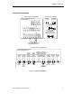
Verify that the 50/60 Hz DIP switch has been set to the appropriate setting, as
instructed in Startup, Operation, and Maintenance Manual (125-3201).
( ) 6.
Inspect the security of the supply line power, ground connections, and all control circuit
connections as identified in the SED2 documents.
IMPORTANT: Confirm that the incoming line power supply connects to the drive
input terminals (L1(r), L2(s), L3(t)) and NOT to the output motor
terminals (T1(u), T2(v), T3(w)).
IMPORTANT: Double check all power wires (L1(r), L2(s), L3(t)) and motor wires
(T1(u), T2(v), T3(w)) to make sure that they are securely tightened
down to their respective lugs. Loose wire connections may cause
problems at any time, and are not covered under warranty.
( ) 7.
Review the installer’s “as wired” schematic. Determine where the motor “safety circuit”
is connected. Verify that the customer’s emergency contacts are properly terminated in
the drive’s safety shutdown circuit or bypass panel.
Verify that all other field-installed wires are correctly terminated (including the shields).
( ) 8. Record the motor(s) nameplate information:
Voltage:
Service Factor: _________________ /Efficiency ____
Full Load Amps (FLA): ______________________ RPM:
_
______________________
_
( ) 9. Verify that the input voltage matches the drive’s rating.
( ) 10. Verify that the motor is wired for the application voltage.
( ) 11.
IMPORTANT: Verify that the motor rated full load amps (FLA) does NOT exceed
the rated output current of the drive controlling it.
When multiple motors are simultaneously operated by the drive, the sum of all motor
rated FLA values must be less than or equal to that of the bypass controlling them.