SED2 VFD NEMA Type 3R and 3R Harsh Environment (3RHE) Bypass Operating Instructions Item Number 125-3377, Rev.
SED2 VFD NEMA Type 3R and Type 3R Harsh Environment (3RHE) Bypass Operating Instructions
NOTICE The information contained within this document is subject to change without notice and should not be construed as a commitment by Siemens Building Technologies, Inc. Siemens Building Technologies, Inc. assumes no responsibility for any errors that may appear in this document. All software described in this document is furnished under a license and may be used or copied only in accordance with the terms of such license.
Table of Contents Table of Contents How to Use this Manual ................................................................................................1 Manual Organization ..................................................................................................1 Manual Notations .......................................................................................................1 Where To Send Comments .......................................................................................
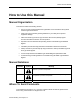
How to Use this Manual How to Use this Manual Manual Organization This manual contains the following sections: • How to Use this Manual describes the organization of this manual and the symbols used throughout this manual. • Safety Instructions provides general guidelines for your safety and to prevent equipment damage. • SED2 VFD NEMA Type 3R and Type 3R Harsh Environment (3RHE) Bypass Overview describes the function and components.
SED2 VFD NEMA Type 3R/3RHE Bypass Operating Instructions Reference Documents The following SED2 VFD documentation is available from your local Siemens Building Technologies representative: 2 • SED2 VFD Startup, Operation & Maintenance Manual (125-3201) • SED2 VFD Parameter Reference Guide (125-3214) • SED2 Variable Frequency Drives Submittal Sheet (154-042) • SED2 VFD NEMA Type 3R and Type 3R Harsh Environment (3RHE) Bypass Submittal Sheet (154-062) • SED2 VFD Conventional Bypass Option Submitta
Safety Instructions Safety Instructions The following general guidelines are provided for your safety, to prevent damage, and to extend the service life of the SED2 product and any connected equipment. Read this information carefully. Specific Warnings, Cautions, and Notes are provided in the relevant sections of this manual. WARNINGS: • The SED2 uses hazardous voltages and controls potentially dangerous rotating mechanical parts.
SED2 VFD NEMA Type 3R/3RHE Bypass Operating Instructions SED2 VFD NEMA Type 3R/3RHE Bypass Overview During normal operation of a NEMA Type 3R/3RHE Bypass in a typical application, the input and output contactors close and the SED2 operates the motor (Figure 1). The bypass contactor provides the ability to operate the motor on utility power and eliminate the SED2 from the motor control circuit.
SED2 VFD NEMA Type 3R/3RHE Bypass Overview RELAYS INPUT CONTACTOR OUTPUT CONTACTOR CONTROL TRANSFORMER CONTROL TERMINAL BLOCK LINE REACTOR OUTPUT CONTACTOR CONTROL TRANSFORMER RELAYS BYPASS CONTACTOR CONTROL TERMINAL BLOCK INPUT CONTACTOR SED2 VFD LINE REACTOR POWER FUSES GROMMETS MOTOR OVERLOAD BYPASS CONTACTOR SED2 VFD BAFFLE DISCONNECT SWITCH HEATER POWER FUSES GROMMETS GROUND LUGS VFD0184R1 DISCONNECT SWITCH VFD0185R1 MOTOR OVERLOAD BAFFLE HEATER GROUND LUGS Enclosure 3R Frame
SED2 VFD NEMA Type 3R/3RHE Bypass Operating Instructions NEMA Type 3R/3RHE Bypass Operation Overview See Figure 6 for NEMA Type 3R/3RHE Bypass control terminals. NOTE: • • • • 6 Drive Mode − Drive output contactor closes (and drive input contactor if supplied). The motor is controlled by the SED2 output. − Change the position of the Drive-Off-Bypass switch to OFF or the bypass stops the SED2 by opening digital input 4, stop 3.
NEMA Type 3R/3RHE Bypass Operation Overview − • If remote bypass operation is also selected, the motor will not run on bypass until the contact for the Customer Remote Start Input closes. Safety Input − Requires a jumper between bypass control terminals 3 and 4. Jumper is supplied from the factory. − Contact must be closed for the motor to be run in either the drive or bypass modes. WARNING: This contact disconnects the 120 Vac control power circuit.
SED2 VFD NEMA Type 3R/3RHE Bypass Operating Instructions Installation Environmental Conditions NEMA Type 3R/3RHE enclosed bypasses are manufactured for outdoor locations, not in direct sunlight. The 3R rating provides a degree of protection to the enclosed VFD and electrical control components from falling rain, snow, and from damage caused by the formation of ice. The ambient temperature must be between 14°F and 104°F (-10°C to 40°C) and the relative humidity must be 0% to 95% non-condensing.
Installation Dimensions and Weights # ) $) # ) ) 8.
SED2 VFD NEMA Type 3R/3RHE Bypass Operating Instructions Mounting 1. Punch appropriate conduit holes for control, motor, and input power wiring (Figure 4). CAUTION: To maintain the NEMA Type 3R/3RHE enclosure rating, use only fittings rated 3R or rain tight, or for wet locations. 2. Mount NEMA Type 3R/3RHE Bypass enclosure in location per job drawings. • To ensure safe installation, verify that the surface of the mounting location is level.
Installation FAN/FINGER GUARD EXHAUST BYPASS ON LIGHT DISCONNECT SWITCH DRIVE-OFF-BYPASS SWITCH DRIVE TEST ON-OFF SWITCH DOOR ANTI-LOCK DEFEATABLE MECHANISM HEATER/FINGER GUARD AIR INLET CONDUIT LOCATION (SHADED AREA ONLY) 1 (25) 1 (25) 12 (305) 1 (25) Figure 5. Enclosure 3R Frame ABC and 3RHE Frame B. Dimensions in Inches (Mm).
SED2 VFD NEMA Type 3R/3RHE Bypass Operating Instructions Wiring Connections See Figure 8 through Figure 13 for all NEMA Type 3R/3RHE Bypass wiring. NOTE: 1. Do not mix control, motor, and input wiring in the same conduit. Run separate wire types with maximum possible separation. WARNING: Failure to follow appropriate VFD wiring practice can result in sub-standard system operation and may damage control components. 2.
Installation OPTIONAL INPUT LINE REACTOR (SUPPLIED LOOSE) POWER SUPPLY 3 PHASE 60 Hz A1 A2 B1 B2 C1 C2 GND OPTIONAL SUPPLEMENTARY POWER FUSES - MAIN SHORT CIRCUIT PROTECTION BY OTHERS (SEE NOTE 1) DISC1 FU1 L1 1L1 2L1 (T1) (L1) L2 1L2 2L2 (T2) (L2) 2L3 L3 1L3 (T3) (L3) OPTIONAL DRIVE INPUT CONTACTOR GND M3 3L1 GND LUG (1) (2) 3L2 (3) (4) M1 (5) (6) (3) (4) (1) (2) OPTIONAL INPUT LINE REACTOR A1 VFD1 A2 B1 B2 C1 C2 3L3 (5) (6) ONLY SUPPLIED ON UNITS WITH BYPASS R U S V T W U M2 (1)
SED2 VFD NEMA Type 3R/3RHE Bypass Operating Instructions DRIVE CONTROL TERMINATIONS AO2+ ISO 0VDC P+ RL2 COM RL2 NC 24 25 EXTERNAL 0 TO 10V 2 3 ISO 24VDC AIN2+ AIN2- 7 8 9 10 11 RR VFD 24 VDC POWERED 0/4 mA DEVICE (POWER CONSUMPTION CANNOT EXCEED 100mA) 2 3 4 9 28 mA POWER 109 DIN4 6 108 DIN3 5 105 DIN2 AIN1+ 4 DIN1 +0VDC 3 AIN1- +10VDC 2 - 4.
Installation 116 1L2 FU2 116 1L1 [H1] OL1 (96) 4 [H3] [H2] [X1] [X2] FU3 1 SECONDARY VOLTAGE 115 VAC [XF] (95) [H4] 2 ESSENTIAL ESSENTIAL 15 SERVICE 16 13 SERVICE 14 JUMPER ACTIVE ENABLED 5 1 ESR CUSTOMER REMOTE 2 START 3 6 X2 ESR (14) (13) (8) (12) 5 CUSTOMER SUPPLIED 4 SAFETIES 3 TRANSFORMER PRIMARY CONTACTS: 230/480/575V PRIMARY VOLTAGE. ACTUAL CONNECTIONS VARY WITH VOLTAGE.
SED2 VFD NEMA Type 3R/3RHE Bypass Operating Instructions OUTPUT CONTACTOR RELAYS INPUT CONTACTOR NOTE: Grommets, Baffle and Heater components not present in 3RHE models.
Installation POWER FUSES INPUT CONTACTOR CONTROL TRANSFORMER OUTPUT CONTACTOR LINE REACTOR FAN SED2 VFD BYPASS CONTACTOR MOTOR OVERLOAD GROMMETS (5) TERMINAL BLOCK BAFFLE DISCONNECT HEATER GROUND LUGS (2) AIR FILTER MOTOR OVERLOAD T1 T2 T3 DISCONNECT L1 L2 L3 GROUND LUGS VFD0192R1 CONTROL INPUT MOTOR WIRING POWER WIRING WIRING INPUT POWER WIRING TO DISCONNECT L1, L2, L3 AND TO GROUND LUG MOTOR WIRING TO MOTOR OVERLOAD T1, T2, T3, AND TO GROUND LUG Figure 13.
SED2 VFD NEMA Type 3R/3RHE Bypass Operating Instructions Motor Cable Length Motor cable length is given to ensure performance of only the drive, not the suitability of the motor when connected to a drive at this distance. • Maximum motor cable length is 164 ft (50 m). • See Figure 11 for installation notes. ! 1. Never run control or drive input wires in the same conduit as the drive output wires. 2. Keep the distance from the drive to the motor as short as possible to maximize motor life. 4.
Installation Access to SED2 Connection Terminals To access the mains power and motor terminals, remove the operator panel, cover, and I/O module. 1 5192J09 5192J08 1 Removing Operator Panel (BOP or AOP). 1 5192J16 2 Removing Terminal Cover Figure 15. Access to Connection Terminals for SED2 Frame Size A. Siemens Building Technologies, Inc.
SED2 VFD NEMA Type 3R/3RHE Bypass Operating Instructions VFD0068R1 1 Figure 16. Access to Connection Terminals for SED2 Frame Size B and C. 1 2 5192J13 3 4 5 6 Figure 17. Access to Connection Terminals for SED2 Frame Size D and E. 20 Siemens Building Technologies, Inc.
Installation 1 2 4 6 3 VFD0070R1 5 Figure 18. Access to Connection Terminals for SED2 Frame Size F. Siemens Building Technologies, Inc.
SED2 VFD NEMA Type 3R/3RHE Bypass Operating Instructions Table 3. Wire Sizes and Tightening Torques for NEMA Type 3R/3RHE Bypasses with 208V Drive. Disconnect Switch Bypass Part Number Enclosure HP Frame Size kW Amps Overload Ground Lug Wire Size * Torque, lb-in (Nm) Wire Size * Torque, lb-in (Nm) Max Torque, Range, Backup Wire lb-in Amps Fuse, Size * (Nm) Amps VBA10.5_3__XHT1 ABC 0.5 0.37 2.3 14-4 35 (4) 18-14 7 - 10.3 (8 - 1.2) 1.8 - 2.5 10 14-2 35 (4) VBA10.7_3__XHT1 ABC 0.
Installation Table 4. Wire Sizes and Tightening Torques for NEMA Type 3R/3RHE Bypasses with 230V - 240V Drive. Disconnect Switch Part Number Bypass Enclosur HP e Frame Size kW Amps Overload Ground Lug Wire Size * Torque, lb-in (Nm) Wire Size * Torque, lb-in (Nm) Max Torque, Range, Backup Wire lb-in Amps Fuse, Size * (Nm) Amps VBA20.5_3__XHT1 ABC 0.5 0.37 2.2 14-4 35 (4) 18-14 7 - 10.3 (8 - 1.2) 1.8 - 2.5 10 14-2 35 (4) VBA20.7_3__XHT1 ABC 0.7 0.55 3.
SED2 VFD NEMA Type 3R/3RHE Bypass Operating Instructions Table 5. Wire Sizes and Tightening Torques for NEMA Type 3R/3RHE Bypasses with 380V - 480V Drive. Part Number* VBA30.5_3__X____** VBA30.7_3__X____** VBA31. _3__X____** VBA31.5_3__X____** VBA32.0_3__X____** VBA33.0_3__X____** VBA35.0_3__X____** VBA37.
Installation Table 6. Wire Sizes and Tightening Torques for NEMA Type 3R/3RHE Bypasses with 500V - 600V Drive. Part Number Bypass Enclosure HP Frame Size Disconnect Switch kW Amps Wire Size * Torque, lb-in (Nm) Overload Wire Size * VBA40.5_3__X & HT1 ABC 0.5 0.37 .9 14-8 35 (4) 18-14 VBA40.7_3__X & HT1 ABC 0.7 0.55 1.3 14-8 35 (4) 18-14 VBA41.0_3__X & HT1 ABC 1.0 0.75 1.4 14-8 35 (4) 18-14 VBA41.5_3__X & HT1 ABC 1.5 1.1 2.1 14-8 35 (4) 18-14 VBA42.0_3__X & HT1 ABC 2.0 1.5 2.
SED2 VFD NEMA Type 3R/3RHE Bypass Operating Instructions Startup Procedures NOTE: The NEMA Type 3R/3RHE Bypass does not allow access to the drive display during normal operation. For startup and programming of the drive, the enclosure door must be open with power applied. This can be done by using the door antilock defeatable mechanism (Figure 4) or by manually actuating the disconnect. This should be done with extreme care, as high voltage will be present.
Startup Procedures ( ) 7. Review the installer’s “as wired” schematic. Determine where the motor “safety circuit” is connected. Verify that the customer’s emergency contacts are properly terminated in the drive’s safety shutdown circuit or bypass panel. Verify that all other field-installed wires are correctly terminated (including the shields). ( ) 8.
SED2 VFD NEMA Type 3R/3RHE Bypass Operating Instructions Keep your Startup, Operation & Maintenance Manuals, option schematics, and any other instructions sent with the drive easily accessible to assist you through the remainder of this startup process. Check Step ( ) 1. Verify that the electrical supply power lines connect to the input device and that the motor leads connect to the output terminals of the overload relay.
Startup Procedures ( ) 9. and then (green start key). The drive will ramp up to To start the Drive, press “10 HZ” (or minimum speed). Verify that the direction of motor rotation is correct. If the direction of motor rotation is wrong, turn the Drive-Off-Bypass switch to OFF; and turn Power Off! Wait for five minutes. NOTE: Swap wires on the motor terminals (T1(u), T2(v)) or on the output terminals of the motor overload relay.
SED2 VFD NEMA Type 3R/3RHE Bypass Operating Instructions ( ) 16. If motor rotation in bypass mode is correct, proceed to Step 17. If motor rotation in bypass mode is NOT correct, check the following and perform as described: ( ) 17. • Turn OFF the incoming power feed to the drive. Since the correct rotation in drive mode was previously established, do not change any output wires at motor. • Instead, verify that power to the input device is OFF.
Startup Procedures Quick Commissioning Procedure Parameter P0010 is the Commissioning Parameter Filter. It allows you to select a group of parameters that can be used for quick commissioning, including motor data, and motor ramp-up and ramp-down settings. It is important to use parameter P0010 to commission the SED2, P0003 to select the access level for using parameters, and P0004 to filter the parameters according to their functionality.
SED2 VFD NEMA Type 3R/3RHE Bypass Operating Instructions Parameter P0010 Description Action Quick Commissioning 1. 0 = Ready to Run 1 = Quick Commissioning Setting/Default Press to access parameter r0000 and to enter the SED2 parameter mode. 2. Repeatedly press to advance to parameter P0010. 3. Press to access the parameter values level. 4. Press 5. Press to confirm and save the P0010 = 1 setting. 30 = Factory Setting Setting = 1 Default = 0 to advance to 1. NOTES: 1.
Startup Procedures Parameter P0304* Description Rated Motor Voltage Action 1. to advance to Press parameter P0304. 2. Press to access the parameter values level. 3. to advance to Press nominal voltage. 4. Press to confirm and save the setting. 1. Press to advance to parameter P0305. 2. to access the Press parameter values level. 3. to advance to Press nominal current. 4. to confirm and save Press the setting. 1. Press to advance to parameter P0307.
SED2 VFD NEMA Type 3R/3RHE Bypass Operating Instructions Table 7. Quick Commissioning Parameters, continued. Parameter P0308*, or P0309 Description Rated Motor cosPhi (P308), or Rated Motor Efficiency (P0309) 0.000 to 1.00 (P0308) or 0.0 to 99.9 (P0309) Action 1. Press to advance to parameter P0308 or P0309. Setting = Motor nameplate P0308 Default = 0.00 2 to access the Press parameter values level. 3. Press to advance to nominal cosPhi or motor efficiency. 4.
Startup Procedures Parameter P0311* Description Rated Motor Speed Action 1. 0 to 40,000 1/min Rated motor speed (rpm) from motor nameplate. Press to advance to parameter P0311. 2. to access the Press parameter values level. A setting of 0 causes an internal calculation of this value. 3 Press to advance to nominal motor speed. Vector control and V/f control with speed controller require this value. 4. Press to confirm and save the setting. 1. Press to advance to parameter P0640.
SED2 VFD NEMA Type 3R/3RHE Bypass Operating Instructions Parameter P0700(0)** Description Selection of Command Source (Start Command) Selects the command source as follows: Action 1. to advance to Press parameter P0700. 2. to access the Press parameter indexes. 3. Press to advance to index [0], IN000, AUTO. 4. to confirm index Press selection. 5. Press 6. to confirm and save Press the setting.
Startup Procedures Parameter P1000[0]** Description Selection of Frequency Setpoint Action 1. to advance to Press parameter P1000. Setting/Default Setting = 2 Default = 2 (Speed Command Source) Selects the frequency setpoint source as follows: 1 = Motor potentiometer setpoint/BOP (keypad) 2 = Analog input 2. to access the Press parameter indexes. 3. Press to advance to index [0], IN000, AUTO. 4 to confirm index Press selection. 5. Press 6. to confirm and save Press the setting. 1.
SED2 VFD NEMA Type 3R/3RHE Bypass Operating Instructions Parameter P1080 Description Minimum Motor Frequency Action 1. 0 Hz to 650 Hz Minimum motor frequency at which the motor will run irrespective of the frequency setpoint. This value applies to both clockwise and counterclockwise rotation. P1082 Maximum Motor Frequency Press to advance to parameter P1080. 2. to access the Press parameter values level. 3. Press to advance to desired value. 4. Press to confirm and save the setting. 1.
Startup Procedures Parameter P1120 Description Ramp-up Time Action 1. 0s to 650s 2. Press to advance to parameter P1120. to access the Press parameter values level. 3. Press value. 4. Press to confirm and save the setting. Setting/Default Site Setting Default = 10 Typical fan = 120s Typical pump = 30s to advance it desired NOTES: 1. Setting the ramp-up time too short can cause the SED2 to trip (F0001 over current, F0002 overvoltage, or F0003 under voltage). 2.
SED2 VFD NEMA Type 3R/3RHE Bypass Operating Instructions Parameter P3900 Description End Quick Commissioning Action 1. 0 = End without motor calculation or factory reset. 1 = End with motor calculation and factory reset (recommended on SED2 without bypass option). 2 =End with motor calculation and with I/O reset. 3 =End with motor calculation but without I/O reset (recommended with SED2 with bypass option). Setting/Default Press to advance to parameter P3900. 2.
Startup Procedures Additional Parameter Settings NOTE: If Display Selection for r0000, parameter P0005=21 (actual frequency), then the BOP display alternately shows setpoint values and the actual value (0 Hz). Flying Start Parameter P1200 Description Flying Start Starts SED2 into a spinning motor by rapidly changing the output frequency of the SED2 until the actual motor speed is found. Then, the motor runs up to setpoint using the normal ramp time. 0 = Flying start disabled.
SED2 VFD NEMA Type 3R/3RHE Bypass Operating Instructions Parameter P1202 Description Motor Current: Flying Start Defines search current used for flying start. Value is in % based on the rated motor current (P0305). Action Setting/Default 1. Press to enter the SED2 parameter mode and to r0000. 2. to advance to Press parameter P1202. 3. to access the Press parameter values level. 4. Press to advance to desired value. 5. Press to confirm and save the setting.
Startup Procedures Automatic Restart CAUTION: Settings 2 through 7 can cause the motor to restart unexpectedly. Parameter P1210 Description Automatic Restart Enables SED2 restart after a supply power break or after a fault. Action 1. 2. to advance to Press parameter P1210. 3. to access the Press parameter values level. 4. Press to advance to desired setting. P1210 = 0, Disabled: Automatic restart is disabled.
SED2 VFD NEMA Type 3R/3RHE Bypass Operating Instructions Automatic Restart Continued Parameter P1211 Description P1210 = 5, Restart after blackout or fault (P1211 disabled): The inverter will acknowledge the faults (F0003 etc.) at power on after blackout and will restart the drive. It is necessary that the ON command is wired via digital input (DIN). P1210 = 6, Restart after supply power brown/blackout or fault (P1211 disabled): The inverter will acknowledge the faults (F0003 etc.
Startup Procedures Automatic Restart Continued Parameter P1211 Description Number of Restart Attempts Specifies the number of times SED2 will attempt to restart after supply power brownout or fault, if P1210 automatic restart is activated. P1212 Time to First Restart Selects the time (seconds) before the SED2 is restarted for the first time if P1210 automatic restart is activated.
SED2 VFD NEMA Type 3R/3RHE Bypass Operating Instructions Vdc Controller Parameter P1240 Description Configuration of Vdc Controller Action Setting/Default 1. Press to enter the SED2 parameter mode and to r0000. 2. Press to advance to parameter P1240. 3. Press to access the parameter values level. 4. Press to advance to desired value. 5. Press to confirm and save the setting. Minimum = 0 Default = 1 Maximum = 3 Enables/disabled Vdc controller.
Startup Procedures Pulse Frequency Parameter P1800 Description Pulse Frequency Sets pulse frequency (kHz) of power switches in SED2. The frequency can be changed in increments of 2 kHz. Pulse frequencies > 4 kHz selected on 380V to 480V units reduce the maximum continuous motor current. Action 1. 2. Press to enter the SED2 parameter mode and to r0000. Press to advance to parameter P1800. 3. Press to access the parameter values level. 4. Press to advance to desired value. 5.
SED2 VFD NEMA Type 3R/3RHE Bypass Operating Instructions Motor Data Identification Parameter P1910 Description Motor Data Identification Action 1. Performs stator resistance measuring. 0 = Disabled. 3 = Identification of the saturation characteristic with parameter change. to enter the SED2 Press parameter mode and to display r0000. 2. Press to advance to parameter P1910. 3. Press to access the parameter values level. 4. Press 1 = Identification of Rs with parameter change.
Startup Procedures Motor Data Identification Continued 6. Press to advance to setting P1910=3. Press to confirm and save the setting. When P1910=3, Alarm 0541 (motor data identification active) is output and internally P0340 is set to 2. Initiate the measuring operation with a continuous (steady-state) ON command. On completion of the motor data identification routine, P1910 resets (P1910=0, motor data identification routine inhibited) and Alarm A0541 is cleared (deleted). 7.
SED2 VFD NEMA Type 3R/3RHE Bypass Operating Instructions Reset to Factory Defaults Parameter P0010 P0970 Description Reset to Factory Default Action Setting/Default 1. Press to enter the SED2 parameter mode and to r0000. P0010: Setting = 30 Default = 0 2. Press to advance to parameter P0010. P0970: Setting = 1 Default = 0 3. Press to access the parameter values level. 4. Press 5. Press to confirm and save the setting. 6. Press P0970. 7. to access the Press parameter values level. 8.
Startup Procedures Required SED2 Parameter Settings The factory programs the following SED2 parameters before shipping. If these parameters are changed or if the SED2 is ever reset to factory default, you must reset these parameters as follows: Parameter P0704 in000 3 P0704 in001 3 P0732 NOTE: Setting 52.2 (default) Changing P0700 resets all digital inputs and P0704 will require programming.
SED2 VFD NEMA Type 3R/3RHE Bypass Operating Instructions Technical Specifications Table 8. NEMA Type 3R/3RHE Bypass Specifications.
Technical Specifications Table 9. Drive Specifications.
SED2 VFD NEMA Type 3R Bypass Operating Instructions Troubleshooting Description of Problem Possible Cause • Commanding the SED2 to start closes the bypass contactor. SED2 required programming for bypass operation has not been programmed in the VFD. Make appropriate VFD programming changes. See Required SED2 Parameter Setting. • Contactors do not close. • Main input short circuit protection has opened. • Control power fuse has opened. • Safety circuit is open.
Troubleshooting Fuses Verify that 120 Vac power is available on the secondary side of the power transformer. If power is not proper, check the Bypass components, such as: • Power transformer • Power transformer fuses (F1, F2, and F3). Table 8 provides fuse replacement information. Table 10. Fuse Replacement Information. NEMA Type 3R Bypass Enclosure ABC 250 VA Transformers Voltage Primary Fuse (F1 and F2) Secondary Fuse (F3) 208V Bussmann/Littlefuse LP-CC-3.5 Bussmann/Littlefuse LP-CC-3.
SED2 VFD NEMA Type 3R Bypass Operating Instructions Siemens Building Technologies, Inc. Industry Sector 1000 Deerfield Parkway Buffalo Grove, IL 60089-4513 Tel: +1 847-215-1000 Fax +1 847-215-1093 Siemens Building Technologies, Ltd. 2185 Derry Road West Mississauga, ON L5N 7A6 Canada Tel: +1 905-819-5800 www.sbt.siemens.