
Operating Instructions

Installation
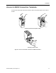
Siemens Building Technologies, Inc. 13
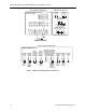
1111098765432
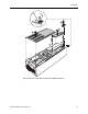
VFD1 CONTROL TERMINALS
RR M2
M2
(6) (10)
M1
(5) (6)
(T1)
OL1
1T1
1T2
(T2)
(T3)
1T3
M
(1) (2)
M2
(1) (2)
U
V
(3)
(5) (6)
(4)
W
(3) (4)
U
VFD1
W
GND
V
R
S
T
AC MOTOR
(CUSTOMER
SUPPLIED)
GND
LUG
GND
GND
LUG
2L1
2L2
2L3
3L1
3L2
3L3
FU1
1L1
1L2
(L1)
L1
L2
(T1)
DISC1
M3
(2)
(4)
(6)
1L3
(L3)
L3
(T3)
GND
(L2)(T2)
1L1 1L2
(5)
(3)
(1)
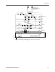
OPTIONAL SUPPLEMENTARY
POWER FUSES - MAIN SHORT
CIRCUIT PROTECTION BY OTHERS
(SEE NOTE 1)
OPTIONAL
DRIVE INPUT
CONTACTOR
POWER
SUPPLY
3 PHASE
60 Hz
TO
STEP-DOWN
CONTROL
TRANSFORMER
B2
A2A1
B1
C2C1
OPTIONAL
INPUT LINE
REACTOR
(SUPPLIED
LOOSE)
A2
B2
C2
A1
B1
C1
OPTIONAL
OUTPUT LOAD
REACTOR
(SUPPLIED
LOOSE)
A2
B2
C2
A1
B1
C1
OPTIONAL
INPUT LINE
REACTOR
ONLY
SUPPLIED
ON UNITS
WITH
BYPASS
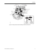
Figure 8. NEMA Type 3R/3RHE Bypass Power Circuit.
NOTES:
1. Branch circuit protection to be provided by installer, per UL508A, if not provided with
drive.
2. For bypass operation modify these drive parameters: P0704 (0) and P0704 (1) = 3.
3. Control and communication wiring should be 300V UL minimum.
4. Communication wiring should be run with maximum separation possible from all other
wiring.
5. Essential service mode operates the motor full speed (bypass) with no protection for the
motor or system.
6. Ensure that automatic bypass will not damage the system before activating.
7. See Table 10 for proper fuse and wire sizes.
8. See Siemens Publication No. 125-3201 for SED2 VFD input/output signal wiring details.