SED2 VFD Electronic Bypass Option Operating Instructions Item Number 125-3208, Rev.
SED2 VFD Electronic Bypass Option Operating Instructions
NOTICE The information contained within this document is subject to change without notice and should not be construed as a commitment by Siemens Building Technologies, Inc. Siemens Building Technologies, Inc. assumes no responsibility for any errors that may appear in this document. All software described in this document is furnished under a license and may be used or copied only in accordance with the terms of such license.
Table of Contents Table of Contents How to Use this Manual................................................................................................1 Manual Organization..................................................................................................1 Manual Notations .......................................................................................................1 Where To Send Comments .......................................................................................
SED2 VFD Electronic Bypass Option Operating Instructions Wiring Example for Interlock ...................................................................................22 Essential Services......................................................................................................23 Description ..............................................................................................................23 Settings ..................................................................................
How to Use this Manual How to Use this Manual Manual Organization This manual contains the following sections: • How to Use this Manual, describes the organization of this manual and the symbols used throughout this manual. • Safety Instructions, provides general guidelines for your safety and to prevent equipment damage. • SED2 VFD Electronic Bypass Option Overview, describes the Electronic Bypass Option Controller board, inputs, outputs, contactors, and keypad.
SED2 VFD Electronic Bypass Option Operating Instructions Reference Documents The following SED2 VFD documentation is available from your local Siemens Building Technologies representative: • SED2 VFD Operation & Maintenance Manual (125-3202), operating instructions and procedures for the SED2 VFD. • SED2 VFD Startup Guide (125-3201), a brief guide to operation offers fast access to all basic information necessary to set up, commission, and operate a SED2 VFD or SED2 VFD with Bypass Option.
Safety Instructions Safety Instructions The following general guidelines are provided for your safety, to prevent damage, and to extend the service life of the SED2 product and any connected equipment. Read this information carefully. Specific Warnings, Cautions, and Notes are provided in the relevant sections of this manual. WARNINGS: NOTE: • The SED2 uses hazardous voltages and controls potentially dangerous rotating mechanical parts.
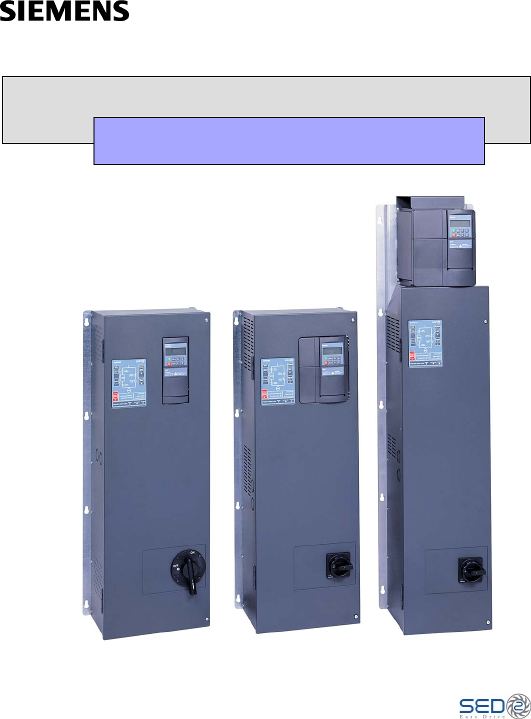
SED2 VFD Electronic Bypass Option Operating Instructions Electronic Bypass Option Overview General Description During normal operation in a typical application, the input and output contactors close and the VFD operates the motor (Figure 1). The bypass contactor provides the ability to operate the motor on utility power and eliminate the VFD from the motor control circuit.
Electronic Bypass Option Overview Controller Board The Controller board is the foundation of the SED2 VFD Electronic Bypass Option. It controls communications to and from the SED2 VFD, keypad, isolated digital inputs, relay/digital outputs, and contactors (Figure 3). SED2 VFD INTERFACE Supports two SED2 VFD non-isolated, digital relay outputs and three SED2 VFD digital inputs. The maximum current draw for a relay output is 2 mA and the voltage between the digital output source and return lines is 24V.
SED2 VFD Electronic Bypass Option Operating Instructions Contactors The Controller board provides two or three relay contact circuits for controlling the Electronic Bypass Option: bypass, input, and output contactors. Each circuit includes a NO relay. Controller board connector J7 enables circuit connections. The relay circuits route power to the SED2 VFD and the motor via the contactors. Controlling the contactors through the relay circuits is the main function of the Controller board.
Electronic Bypass Option Overview VFD0102R1 VFD0101R1 Push Button/Indicator Remote Start Activates the bypass mode and operates the bypass contactor according to the status of the Remote Start input on the Controller board. STOP RESET Opens the output and bypass contactors, disconnecting the motor.
SED2 VFD Electronic Bypass Option Operating Instructions Installation Instructions Environmental Conditions Install the Electronic Bypass Option in a heated, indoor controlled environment that is free of moisture and conductive contaminants such as condensation and dust. The air entering the unit for ventilation/cooling must be clean and free from corrosive materials. The ambient temperature must be between 32°F and 104°F (0°C to 40°C) and the relative humidity must be 0% to 95% noncondensing.
Installation Instructions Mounting 1. To ensure safe installation, verify that the surface of the mounting location is level. 2. Mount the Electronic Bypass Option vertically with the SED2 VFD operator panel, Electronic Bypass Option keypad, and disconnect accessible. Depth With Handle 10.4 (26) = Protective Shield Depth With Handle 9.6 (24) Depth With Handle 9.6 (24) 13.2 (34) 11.5 (29) 20.8 (53) 1 (2.5) 2 (5) 2.9 (7.4) 4 (10) 1.5 (3.8) 57.5 (146) 48 (122) 34 (86) 10.5 TYP (27) 12.
SED2 VFD Electronic Bypass Option Operating Instructions Electrical Installation See Figure 6 for all Electronic Bypass Option wiring. 1. Route shielded twisted pair (recommended wire type) cable, 24 gauge minimum control wiring in conduit through knockout and into housing (Figures 7 through 9). Connect control wiring per job-specific drawings. NOTES: • Terminate shield at control device. • Control wiring is 12 to 26 AWG and tightening torque is 5 lb-in. 2.
Installation Instructions SED2 VFD SED2 VFD CONTROLLER BOARD INPUT CONTACTOR (OPTIONAL) INPUT CONTACTOR (OPTIONAL) J2 CONTROL WIRING (DIGITAL INPUTS/ OUTPUTS) VIA 2 KNOCKOUTS COMMUNICATIONS WIRING (P1) VIA 1 KNOCKOUT CONTROLLER BOARD COMMUNICATIONS WIRING (P1) VIA 1 KNOCKOUT J2 CONTROL WIRING (DIGITAL INPUTS/ OUTPUTS) VIA 2 KNOCKOUTS J1 REACTOR (OPTIONAL) REACTOR (OPTIONAL) J1 TRANSFORMER TRANSFORMER POWER FUSES (OPTIONAL) OUTPUT CONTACTOR GROUND LUGS BYPASS CONTACTOR GROUND LUGS BYPASS
SED2 VFD Electronic Bypass Option Operating Instructions Table 1. Wire Sizes and Tightening Torques for Electronic Bypass Option with 208V Drive. Circuit Breaker Part Number Frame Size VBE10.5---- A 0.5 0.37 VBE10.7---- A 0.7 0.55 VBE11.0---- A VBE11.5---- B VBE12.0---VBE13.0---- Hp kW Amps Disconnect Switch Overload Max Backup Wire Torque, Fuse, Size * lb-in Amps Wire Size * Torque, lb-in Wire Size * Torque, lb-in Wire Size * Torque, lb-in 2.
Installation Instructions Table 2. Wire Sizes and Tightening Torques for Electronic Bypass Option with 230-240V Drive. Circuit Breaker Part Number Frame Size VBE20.5---- A 0.5 0.37 VBE20.7---- A VBE21.0---- A VBE21.5---VBE22.0---- Hp kW Amps Disconnect Switch Overload Max Backup Wire Torque, Fuse, Size * lb-in Amps Wire Size * Torque, lb-in Wire Size * Torque, lb-in Wire Size * Torque, lb-in 2.2 14-10 32 18-10 13-17 18-14 7-10.3 1.8-2.5 10 14-2 35 0.7 0.55 3.
SED2 VFD Electronic Bypass Option Operating Instructions Table 3. Wire Sizes and Tightening Torques for Electronic Bypass Option with 380-480V Drive. Circuit Breaker Part Number Frame Size VBE30.5---- A 0.5 0.37 VBE30.7---- A VBE31.0---- A VBE31.5---VBE32.0---- Hp kW Amps Disconnect Switch Overload Ground Lug Max Backup Wire Fuse, Size * Amps Wire Size * Torque, lb-in Wire Size * Torque, lb-in Wire Size * Torque, lb-in Range, Amps 1.1 14-10 32 18-10 13-17 18-14 7-10.3 .7-1.
Installation Instructions Table 4. Wire Sizes and Tightening Torques for Electronic Bypass Option with 500-600V Drive. Circuit Breaker Part Number Frame Size VBE40.5---- C 0.5 0.37 VBE40.7---- C VBE41.0---- C VBE41.5---VBE42.0---- Hp kW Amps Disconnect Switch Overload Ground Lug Max Backup Wire Fuse, Size * Amps Wire Size * Torque, lb-in Wire Size * Torque, lb-in Wire Size * Torque, lb-in Range, Amps .9 14-10 32 18-10 13-17 18-14 7-10.3 .7-1.0 0.7 0.55 1.
SED2 VFD Electronic Bypass Option Operating Instructions Startup Procedures Safety Precautions WARNING: When you connect input power to the Electronic Bypass Option, the motor terminals are energized even if the motor is not running. Do not make any connections with input power connected to the Electronic Bypass Option. Disconnect and lock out power to the drive before servicing it. Failure to disconnect input power may cause serious injury or death.
Startup Procedures 3. Perform VFD commissioning per the SED2 VFD Operation & Maintenance Manual (Document No. 125-3202). If using the Quick Commissioning mode, end this mode with P3900=3 to run a motor calculation without resetting the SED2 to factory defaults. 4. After basic VFD operation is established and verified, turn VFD power off via the Electronic Bypass Option and verify that no dangerous voltages are present in the enclosure. 5.
SED2 VFD Electronic Bypass Option Operating Instructions Required SED2 VFD Parameter Settings The following SED2 parameters are programmed by the factory before shipping. If these parameters are changed or if the SED2 VFD is ever reset to factory default, you must reset these parameters as follows: Parameter Setting P0748 P0702 in000 3 P0702 in001 3 P0731 52.3 NOTES: 1.
Application Feature Setup Application Feature Setup Remote Start Input Overview • VFD Fault • Programmable Output • Drive Select • Bypass Select • Bypass Running • Overload Fault Remote Safety #1 Remote Safety #2 DIGITAL INPUTS Interlock Start Essential Services Overload Trigger DIGITAL OUTPUTS VFD0114R1 The Controller board supports six isolated digital inputs and six digital relay outputs for customer use (Figure 10).
SED2 VFD Electronic Bypass Option Operating Instructions The Electronic Bypass Option will return to VFD mode operation as soon as the SED2 Relay in control opens. When the Electronic Bypass Option returns to VFD mode operation, the following occurs: • The SED2 Relay opens, the Programmable Output on the Controller board opens, and the bypass contactor opens. • The output contactor closes. NOTE: All safety conditions must be met for VFD mode operation.
Application Feature Setup Interlock Description The Interlock feature (also called damper end switch logic) enables the SED2 VFD outputs to inhibit motor start until a safety condition (proofing sequence) is confirmed. Any call to start the motor from the SED2 VFD or bypass does not directly start the motor, but instead initiates the following Interlock procedure: • The Interlock Start Logic Enable indicator is ON. Proofing is required to start in VFD or bypass mode.
SED2 VFD Electronic Bypass Option Operating Instructions ON 4 5 5 1 SW1 For proper Interlock operation, set the following VFD parameters: VFD0118R1 1 2 2 3 The Interlock Start Logic Enabled indicator is on steady. ON NOTE: 3 4 The Interlock feature requires that Controller board DIP Switch 3 is set ON.
Application Feature Setup Essential Services Description The Essential Services feature allows full-power bypass mode control of the motor during an emergency scenario. Activation of Essential Services overrides any other selected operation. Essential Services ensures that the bypass contactor will not open when a safety input or overload opens. Power goes directly to the motor. NOTES: 1.
SED2 VFD Electronic Bypass Option Operating Instructions Interlock and Auto Bypass on VFD Fault Description Interlock and Auto Bypass features are both active. Auto bypass now becomes auto bypass on a VFD fault only (bypass is initiated by the SED2 Fault and this digital output must always be programmed to VFD fault). • All set-up is the same as with Interlock (see the Interlock section in Application Feature Setup). • Hand bypass is now initiated by SED2 Fault.
Technical Specifications Technical Specifications Specifications Description 208V, 3AC±10% Input Voltage (3 phase) 230V, 3AC±10% 460V, 3AC ±10% 575V, 3 AC ±10% Digital Inputs Six Digital Inputs as follows: • Remote start input • Remote safety 1 • Remote safety 2 • Interlock start • Essential services • Overload trigger Inputs require a contact closure capable of providing a low impedance path at currents less than 20 mA.
SED2 VFD Electronic Bypass Option Operating Instructions Troubleshooting WARNING: Always disconnect all power sources before opening the SED2 VFD Electronic Bypass Option. Power-on Initialization Failure (Unit Fault Condition) During power-on initialization, a unit fault condition occurs if the Electronic Bypass Option did not pass the basic sanity test. Rather than flash normally, the basic sanity test indicator pauses, flashes a fault code, and then repeats. Table 5 shows the fault codes.
Troubleshooting Override Jumper An Override Jumper (J8) is supplied on the Controller board. Moving this jumper to the override position removes the Controller board and its keypad from the control and closes the drive output contactor (and the input contactor if supplied). BPEC BPEC J2 J1 J1 J8 J8 VFD0121R1 J2 OVERRIDE JUMPER J8 SHOWN IN NORMAL POSITION OVERRIDE JUMPER J8 SHOWN IN OVERRIDE POSITION Figure 11. Override Jumper J8 Location and Positions.
SED2 VFD Electronic Bypass Option Operating Instructons Table 6. Fuse Replacement Information. Bypass Option Part Number Primary Fuse (F3 and F4) Secondary Fuse (F2) VBE10.5D120X – VBE17.5B13LX Bussmann/Littlefuse LP-CC-1 Bussmann/Littlefuse LP-CC-6/10 VBE110.D120X – VBE110.B13LX Bussmann/Littlefuse LP-CC-2 Bussmann/Littlefuse LP-CC-1 1/4 VBE115.D120X – VBE160.B13X Bussmann/Littlefuse LP-CC-3 Bussmann/Littlefuse LP-CC-2 VBE20.5D120X – VBE27.
Troubleshooting VFD Bypass Hand Start Input Contactor Bypass Contactor Remote Start Overload Relay Motor STOP RESET Auto Bypass Enabled VFD Fault Safety Fault Essential Services INTERLOCK START LOGIC NOTE: 3-Contactor Keypad Shown.
SED2 VFD Electronic Bypass Option Operating Instructions Siemens Building Technologies, Inc. 1000 Deerfield Parkway Buffalo Grove, IL 60089-4513 Tel: +1 847-215-1000 Fax +1 847-215-1093 Siemens Building Technologies, Ltd. 2 Kenview Blvd. Brampton, Ontario Canada L6T 5E4 Tel: +1 905-799-9937 www.sbt.siemens.com Item Number 125-3208, Rev.