SED2 Operation & Maintenance Manual
SED2 Operation & Maintenance Manual 125-3202 Rev.
Rev. 3.0, September, 2002 NOTICE The information contained within this document is subject to change without notice and should not be construed as a commitment by Siemens Building Technologies, Inc. Siemens Building Technologies, Inc. assumes no responsibility for any errors that may appear in this document. All software described in this document is furnished under a license and may be used or copied only in accordance with the terms of such license.
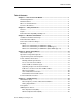
Table of Contents Table of Contents Chapter 1 — How To Use This Manual .......................................................................1 Manual Organization .................................................................................................1 Manual Notations.......................................................................................................2 Where To Send Comments .......................................................................................
SED2 Operation & Maintenance Manual Buttons on the BOP and AOP ..............................................................................25 Default Commissioning Settings................................................................................27 Commissioning Prerequisites ....................................................................................28 Motor Data for Commissioning Parameters ..............................................................29 Quick Commissioning Procedure ....
Table of Contents Dimensions and Weights...........................................................................................72 Unit-specific Data.......................................................................................................72 Options ......................................................................................................................76 Chapter 9 — SED2 Communications ..........................................................................77 Overview.......
SED2 Operation & Maintenance Manual iv Siemens Building Technologies, Inc.
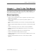
Chapter 1 – How to Use This Manual Chapter 1 — How To Use This Manual This manual is written for installers, technicians, service engineers, operators, and users of Siemens Building Technologies SED2 Variable Frequency Drives (“SED2 or SED2 drives”). This manual contains information to mount, install, set parameters, and commission SED2 drives so they provide effective and trouble-free operation.
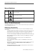
SED2 Operation & Maintenance Manual Manual Notations Notation Symbol Meaning DANGER: Indicates that personal injury or loss of life may occur if you do not perform a procedure as specified. WARNING: Indicates that equipment damage, or loss of data may occur if you do not perform a procedure as specified. CAUTION: Indicates that equipment damage, or loss of data may occur if you do not perform a procedure as specified. NOTES: (no symbol) Provides other important information or helpful hints.
Chapter 2 – Safety Instructions Chapter 2 — Safety Instructions General The following general guidelines are provided for your safety, to prevent damage, and to extend the service life of the SED2 product and any connected equipment. Read this information carefully. Specific Warnings, Cautions, and Notes are provided in the relevant sections of this manual. :$51,1* NOTE: • The SED2 uses hazardous voltages and controls potentially dangerous rotating mechanical parts.
SED2 Operation & Maintenance Manual Repair Only Siemens service departments, repair centers authorized by Siemens Building Technologies, or authorized personnel who are fully acquainted with the SED2 may repair this equipment. Replace defective parts or components using original manufacturer parts. DANGER: Always disconnect the power source before opening the SED2.
Chapter 3 – Mechanical Installation Chapter 3 — Mechanical Installation Installation after Extended Storage After an extended period of storage, recharge the capacitors in the SED2. Calculate the storage time from the date of manufacture, and not from the date of delivery. The recharge procedure varies according to the storage period as follows: Period of Storage Required Action Preparation Time 1 year or less Recharging not required.
SED2 Operation & Maintenance Manual Height Above Sea Level: If installing the SED2 at an altitude of higher than 3280 ft (1000 m), derating is required. Overheating/Ventilation: Install the SED2 vertically for optimum ventilation. Do not obstruct the SED2 vents. Additional ventilation may be required if the drive is mounted horizontally. If installing SED2 drives one above the other, the necessary clearance varies according to the size and protection standard of the drives.
Chapter 3 – Mechanical Installation Mounting Dimensions and Mounting for SED2 Drives (IP20) Table 1. Overall Dimensions of SED2 (IP20). Dimensions in Inches (Millimeters). Frame Size Height Width Depth Tightening Torque lb-in (Nm) Mounting Specification Weight lb (kg) A 6.8 (173) 2.9 (73) 5.9 (149) 2 x M4 Bolts, Nuts, and Washers, or Connecting to DIN rail 22 (2.5) 2.9 (1.3) B 8.0 (202) 5.9 (149) 6.8 (172) 4 x M4 Bolts, Nuts, and Washers 22 (2.5) 7.5 (3.4) C 9.6 (245) 7.3 (185) 7.
SED2 Operation & Maintenance Manual Dimensions and Mounting for SED2 Drives (NEMA Type 1) Table 2. Overall Dimensions of SED2 (NEMA Type 1) Drives Assembled with a Protective Shield and a Gland Plate. Dimensions in Inches (Millimeters). Frame Size 8 Height Width Depth Weight lb (kg) A 9.1 (231) 2.9 (73) 5.9 (149) 3.2 (1.5) B 11.8 (300) 5.9 (149) 6.8 (172) 8.3 (3.8) C 13.8 (351) 7.3 (185) 7.7 (195) 13.6 (6.2) D 24.6 (625) 10.8 (275) 9.6 (245) 37.5 (17.1) E 29.7 (754) 10.
Chapter 3 – Mechanical Installation Dimensions and Mounting for SED2 Drives (IP54, NEMA Type 12) Table 3. Overall Dimensions and Mounting Clearances for SED2 (IP54, NEMA Type 12). Dimensions in Inches (Millimeters). Frame Size Overall Dimensions Height Width Mounting Clearance Depth Top Bottom Mounting Specification Sides Tightening Torque lb-in (Nm) B 15.2 (385) 10.6 (270) 10.6 (268) 5.9 (150) 5.9 (150) 3.9 (100) 4 x M6 Bolts, Nuts, and Washers 44 (5) C 23.9 (606) 13.8 (350) 11.
SED2 Operation & Maintenance Manual Chapter 4 – Electrical Installation DANGER: 10 • To ensure safe operation of the equipment, authorized persons must install and commission it in full compliance with the warnings, cautions, and notes in this manual. Authorized persons must also follow general and regional installation and safety regulations regarding work on sites with hazardous voltages (EN 50178) and relevant regulations for the correct use of tools and personal protective equipment.
Chapter 4 – Electrical Installation Motor Cable Length Maximum motor cable length is as follows: • 328 ft (100 m) for shielded cables • 164 ft (50 m) for unshielded cables NOTES: 1. For SED2 drives with EMC filters, the maximum cable length is 82 ft (25 m). For cables shorter than 82 ft (25 m), the EMC guideline for filtered devices does not apply. 2. If connecting multiple motors to one SED2, the total length of the individual motor cables must not exceed the maximum motor cable length. 3.
SED2 Operation & Maintenance Manual Operation in Ungrounded Systems IP20: SED2 drives (IP20) can operate in ungrounded systems, and remain in operation when an input phase connects to ground. In the event of an output phase with a ground fault, the SED2 switches off and displays fault code F0001. NOTE: Operation in ungrounded systems is possible only using the SED2 (IP20) without filter. IP54: SED2 drives (IP54) cannot operate in ungrounded systems.
Chapter 4 – Electrical Installation 1 2 3 5192Z02 Figure 4. Disconnecting Y Capacitor in SED2 Frame Size B and C. ON 1 20 21 22 23 24 25 12 13 14 15 16 17 26 27 28 29 30 1 2 3 4 5 6 7 8 9 10 11 2 PE Torx driver T20 M4 S crew 5192Z 0 3en Figure 5. Disconnecting Y Capacitor in SED2 Frame Size D and E. Siemens Building Technologies, Inc.
SED2 Operation & Maintenance Manual T30 Torx screwdriver 5192J17en M6 Figure 6. Disconnecting Y Capacitor in SED2 Frame Size F. Power and Motor Connections Warning and Safety Instructions DANGER: 14 • Always isolate the power cables before connecting them to the SED2. • Never switch on the SED2 with the cover open. • Always use insulated tools when working on the power and motor terminals. • Ensure that the terminal cover is replaced properly after connecting the power and motor cables.
Chapter 4 – Electrical Installation :$51,1* • Verify that the SED2 and motor are correctly sized for the mains voltage. Ensure that the SED2 is suited for the motor output. • Check that the mains cables are correctly sized for the anticipated use. • Confirm that appropriate circuit breakers or fuses have been installed between the mains supply and the SED2. • Never use high-voltage insulation test equipment on any cables connected to the SED2.
SED2 Operation & Maintenance Manual 1 1 5192J12 2 5192J13 3 Figure 8. Access to Connection Terminals for SED2 Frame Size B and C. 4 5 6 Figure 9. Access to Connection Terminals for SED2 Frame Size D and E. 1 2 4 6 3 5 4 J1 92 51 Figure 10. Access to Connection Terminals for SED2 Frame Size F. 16 Siemens Building Technologies, Inc.
Chapter 4 – Electrical Installation Power and Motor Terminal Layout R+ DC L3 B- L3 DC+ L2 DC- L2 DC- DC+ B+ L1 L1 V B- U V W W 5192Z05 U DC R+ (Ground) Figure 12. Power and Motor Terminal Layout for SED2 Frame Size B and C. Figure 11. Power and Motor Terminal Layout for SED2 Frame Size A. L1 L2 5192Z06 PE PE (Ground) L3 DC- DC+ B+ DC R+ B- U V R+ B+ B+ DC- B- DC+ DC+ DC+ L2 L3 U V W W PE L1 5192Z07 Figure 13.
SED2 Operation & Maintenance Manual Cable Cross-Sections for Power and Motor Cables Table 4. Cable Cross-Sections for input Voltage Range 3 AC 200V through 240V. Output rating kW (hp) Min. cross-section Max. cross-section of supply cable of supply cable 2 2 AWG (mm ) AWG (mm ) Min. cross-section of motor cable 2 AWG (mm ) Max. cross-section of motor cable 2 AWG (mm ) 0.37 (.50) 17 (1) 13 (2.5) 17 (1) 13 (2.5) 0.55 (.75) 17 (1) 13 (2.5) 17 (1) 13 (2.5) 0.75 (1.0) 17 (1) 13 (2.
Chapter 4 – Electrical Installation Table 5. Cable Cross-Sections for input Voltage Range 3 AC 380V through 480V. Output rating kW Min. cross-section Max. cross-section of supply cable of supply cable 2 2 AWG (mm ) AWG (mm ) Min. cross-section of motor cable 2 AWG (mm ) Max. cross-section of motor cable 2 AWG (mm ) 11 (15) 9 (6) 7 (10) 9 (6) 7 (10) 15 (20) 7 (10) 2 (35) 7 (10) 2 (35) 18.
SED2 Operation & Maintenance Manual SED2 To change the direction of rotation of the motor, cross-connect two of the output conductors on the SED2 (Figure 15). SED2 Reverse Output Phase Sequence parameter P1820 can also reverse the direction of rotation. U U V V W W U U V V W W M M 5192V01 Direction of Rotation Figure 15. Direction of Motor Rotation. Motor terminal board The required supply voltage and method of connection are indicated on the motor rating plate.
Chapter 4 – Electrical Installation D C /R + D C /B + 2 0 0 - 2 4 0 V 3 A C 3 8 0 - 4 8 0 V 3 A C 5 0 0 - 6 0 0 V 3 A C U L 1 L 2 V W L 3 P E B - F ilte r 3 P E P E M L 1 L 2 L 3 P E + 1 0 V D C 1 + 2 0 V D C 4 1 2 D / A L G -N i 1 0 0 0 V : 0 2 I: 0 4 - 1 - 1 - 2 - 2 0 V 0 V 0 m A 0 m A A O U T 1 3 A IN 1 2 6 D / A A O U T 2 1 1 L G -N i 1 0 0 0 V : 0 2 I: 0 4 - 1 - 1 - 2 - 2 0 V 0 V 0 m A 0 m A A / D 2 1 0 V 9 Is o la te d 5 0 m A @ (o u tp u t) D IN 4 8 1 6 R e la y
SED2 Operation & Maintenance Manual Chapter 5 — Commissioning :$51,1* 22 • Only authorized personnel trained in the setup, installation, commissioning, and operation of the SED2 may work on the product and plant. • SED2 drives operate at high voltages. In some components, operation of electrical equipment involves using dangerous voltages.
Chapter 5 – Commissioning DIP Switch Settings Motor Frequency & Units of Measurement Switches Analog Input Switches In all versions of the SED2, the DIP switches for selecting the motor frequency and North American or European units of measurement are located on the control board under the I/O module. (See Chapter 4, Access to Connection Terminals for I/O module and control board locations.
SED2 Operation & Maintenance Manual Prerequisites 9 Prerequisites Is the output of the SED2 motor rating? Is the operating voltage range OK? Is the rated voltage of the SED2 greater than the motor rated voltage? Is the cross-section of the mains cable correct? Are the cross-section and the length of the motor cables correct, and are they connected properly? Are all control lines connected properly? Is the motor not blocked mechanically? Is the medium (water) available for the pump actuator (No dry run)?
Chapter 5 – Commissioning For information on setting and modifying parameters, see the Setting Parameters with the BOP or AOP section in this manual. Advanced Operator Panel (AOP) In addition to the functions of the BOP, the Advanced Operator Panel provides the following functions: • Displays multi-lingual and multi-line plain text. • Displays units of measurement for speed, frequency, direction of motor rotation, and current. • Comments on current parameters, and error messages.
SED2 Operation & Maintenance Manual Operator Panel/Button . Function Change to automatic control Increase value Decrease value Description Places the SED2 VFD in AUTO mode. Press this button to increase the current display value during parameter setting. In manual mode, this button increases the speed (internal motor potentiometer). Press this button to decrease the current display value during parameter setting. In manual mode, this button decreases the speed (internal motor potentiometer).
Chapter 5 – Commissioning Default Commissioning Settings Default settings for operation with the BOP are as follows: Parameter P0100 Description For USA or Europe power setting Default Value for North America (Europe) 0 = 50 Hz, kW (Europe), factory default 1 = 60 Hz, hp (North America) 2 = 60 Hz, kW (North America) The setting of Motor Frequency & Units of Measurement DIP switch 2 overwrites P0100 settings 0 and 1. See the DIP Switch Settings section for details. NOTES: 1.
SED2 Operation & Maintenance Manual Parameter P0700[0] P1000 Description Selection of command source Index [0]: IN000=AUTO, 1st command data set Index [1]: IN001=HAND, 2nd command data set Selection of frequency setpoint Index [0]: IN000=AUTO, 1st command data set Index [1]: IN001=HAND, 2nd command data set Default Value for North America (Europe) 0=Factory default setting 1=BOP (keypad) 2=Terminal 4=USS on BOP link, AOP 5=USS on COM link 6=CB on COM link Default for P0700 is 2.
Chapter 5 – Commissioning Motor Data for Commissioning Parameters Motor parameters can only be modified if Commissioning Parameter Filter P0010=1 (for quick commissioning). The motor control functions of the BOP are disabled by default. Set Selection of Command Source parameter P0700[0]=1 (for BOP) and Selection of Frequency Setpoint P1000[0]=1 (for motor potentiometer setpoint) to enable motor control using the BOP.
SED2 Operation & Maintenance Manual Quick Commissioning Procedure P0010 Start Quick Commissioning 0 = Ready to Run 1 = Quick Commissioning 30 = Factory Setting NOTE: P0010 must always be set back to 0 before operating the motor. However, if P3900 = 1 is set after commissioning, this is done automatically. User Setting P0100 Operation for Europe/ N.
Chapter 5 – Commissioning Setting Parameters with the BOP or AOP The following table describes the procedure for modifying parameter P1082, Maximum Motor Frequency. Use this table as a guide for setting all other parameters with the BOP. NOTE: You can change motor data parameters only if P0010=1. To start the motor, reset P0010=0. Modify P0004, parameter filter function: Step Action 1 Press 2 Repeatedly press 3 Press to access the parameter values level.
SED2 Operation & Maintenance Manual Step Action Resulting display 2 P(1) 7 Press to return to P0010. 8 Press to access the parameter values level. 9 Press to restore the value of Commissioning Parameter Filter P0010 to 0 (ready). 10 to confirm and save the value, and to exit from the parameter Press values level. 11 Press 12 to revert to the standard motor display (as defined by the Press customer).
Chapter 5 – Commissioning NOTES: 1. The reset process takes approximately 10 seconds. 2. The parameter list in Appendix A of this manual provides factory default settings. SED2 Operation with the BOP Prerequisites and Notes 1. Set Commissioning Parameter Filter P0010=0 (factory setting) to ensure correct initialization of the RUN command. Set Selection of Command Source parameter P0700[0]=1 (BOP) to enable the BOP start/stop button.
SED2 Operation & Maintenance Manual Testing with the BOP 1. Restore the factory settings in the SED2. See the Resetting SED2 Parameters to Factory Defaults section in this manual. 34 Testing with the AOP 1. Restore the factory settings in the SED2. 2. Press to switch to manual operation. 2. Set Selection of Command Source parameter P0700[0] from 1 to 4 (for AOP). 3. Press to start the motor. 3. Press to stop the motor. 4. Press to switch to manual operation. 5. Press to switch the device on.
Chapter 6 – Programming Chapter 6 — Programming Using the Parameters • Modify SED2 parameters using the BOP, the AOP, or the serial interface. Use the BOP or AOP to enter and modify parameters that define the required characteristics of the SED2, such as motor data, ramp times, and maximum and minimum frequency. • Read-only parameters are identified by the letter “r”, programmable parameters are identified by the letter “P”.
SED2 Operation & Maintenance Manual SED2 Parameter Indices Certain parameters have indices. The indices provide subsets of a particular parameter function. The indexes group together closely related parameter type information. The Appendix A: Parameter Reference List section of this manual lists any indices associated with a parameter.
Chapter 6 – Programming Drive Parameters P0003 User acces level P0010 Commissioning parameter filter r0026 VFD DC-link voltage r0039 - P0040 Energy consumption meter P0100 US / Europe r0206 - r0209 Performance data P1000 - P1028 Frequency setpoint P1080 - P1110 Frequency adjustment Motor Parameters r0021 - r0035 Motor performance data P0304 - P0313 Standard data P0340 Calculation of motor parameters P0601 - P0640 Motor protection P1910 Motor data identification P2000 Reference frequency 200 -240 V 3 AC 3
SED2 Operation & Maintenance Manual Digital Inputs 5192Z17en SED2 Basic Functions 5 DIN1 Stand-alone operation of the SED2 requires external switch-on and switch-off arrangements. The SED2 supports six-digital inputs, DIN1 through DIN6 (Figure 25), and can be extended to eight-digital inputs (DIN7 and DIN8) by using two analog inputs (AIN1 and AIN2). You can program the function of the digital inputs as required.
Chapter 6 – Programming Factory settings: P0701 1 ON/OFF1 – Off as defined via Ramp-Down Time parameter P1121. P0702 12 Reverse (change of rotation). P0703 9 Fault acknowledgement. P0704 15 Fixed setpoint (direct selection). P0705 15 Fixed setpoint (direct selection). P0706 15 Fixed setpoint (direct selection). Index: Example for P0701, applies also to parameters P0702 to P0706. P0701[0]: IN000 (AUTO)=1st command data set (CDS). P0701[1]: IN001 (HAND)=2nd command data set (CDS).
5192Z29 SED2 Operation & Maintenance Manual DIN1 = 0 DIN2 = 1 DIN3 = 1 DIN4 = 0 DIN5 = 1 DIN6 = 1 AIN1 = 0 AIN2 = 1 Figure 28. Example of the Display while Testing Input Signals using Parameter r0722. Digital Outputs Parameter Settings for DO1 and DO2 P0731 to P0732, Digital outputs 1 and 2 The available settings for each digital output is as follows: 52.E Motor running direction right. 52.0 Drive ready. 52.F Inverter overload. 52.1 Drive ready to run. 53.0 DC brake active. 52.2 Drive running. 53.
Chapter 6 – Programming r0747, Invert digital outputs Shows the inverted state of the digital outputs as follows: Bit 00=Invert Digital output 1 (0=no, 1=yes) Bit 01=Invert Digital output 2 (0=no, 1=yes) VFD 24V dc POWERED 0-20 mA DEVICE (Power consumption cannot exceed 100 mA) 2 3 mA 4 Power Analog Inputs The SED2 analog inputs send positioning, control, and feedback signals to the SED2 and convert them to digital signals via A/D converters (ADC).
SED2 Operation & Maintenance Manual Index: P0756[0]: IN000=Analog input 1. P0756[1]: IN001=Analog input 2. Note on dependency: This function is disabled if the analog scaling block is programmed for negative output setpoints (see P0757 to P0760). P0753, Analog input filter time P0753 defines the filter time (PT filter time) in ms for the analog input.
Chapter 6 – Programming P0761, Width of deadband (V/mA) for analog inputs P0761 defines the deadband for the analog inputs. % Setting range: 0 to 10V, or 0 to 20 mA ymax Factory setting: 0 NOTE: y2 -10 -20 P0761[x] = 0: No enabled dead zone. x1 The dead zone runs from 0V (or 0 mA) to the value of P0761, if the values of P0758 and P0760 (y-coordinate for analog input scaling) have the same sign.
SED2 Operation & Maintenance Manual P0773, Smoothing time for analog output signals P0773 enables smoothing for the signal with a PT1 filter and determines the smoothing time in ms for the analog output signals. Setting range: 0 to 1000 ms Signal in % 25 Present output voltage (scaled to P2001, Reference Voltage). 26 Present link voltage (scaled to P2001, Reference Voltage). 27 Present output current (scaled to P2002, Reference Current). Index: P0771[0]: IN000=Analog output 1.
Chapter 6 – Programming P0780: Defines y1 of the output characteristics (factory setting = 10). Example: The factory-set scaling is as follows: P1: 0.0 % = 0 mA or 0V P2: 100.0 % = 20 mA or 10V Index: P0777[0]: IN000=Analog output 1. P0777[1]: IN001=Analog output 2. P0781, Width of deadband for analog outputs P0781 defines the DAC deadband for the analog outputs. % ymax Setting range: 0 to 20 mA, or 0 to10V y2 Factory setting: 0 Index: P0781[0]: IN000=Analog output 1. P0781[1]: IN001=Analog output 2.
SED2 Operation & Maintenance Manual Start Motor Default setting: Terminal 5 (DIN 1, high). Additional settings: See Selection of Command Source parameter P0700 and Function of Digital Inputs 1 to 8 parameters P0701 through P0708. NOTE: The ramp-up and ramp-down smoothing times influence the motor’s start and stop behavior. For more information, see Ramp-Up Time parameter P1120 and RampDown Time parameter P1121 in the Appendix A: Parameter Reference List section of this document.
Chapter 6 – Programming For starting the motor when OFF3 is set, the binary input must be closed (high). If OFF3 is high, the motor can start and stop by OFF1 and OFF2. If OFF3 is low, the motor cannot be started. Control Types (P1300) The different control types of the SED2 control the relationship between the motor speed and the voltage supplied by the SED2.
SED2 Operation & Maintenance Manual P2253 : setpoint source P2261 : setpoint filter timeconstant r 2262 : filtered setpoint P2264 : feedback source P2267 : feedback threshold max P2268 : feedback threshold min P2270 : function sequence P2271 : transducer type r 2272 : scaled feedback P2274 : derivative time r 2273 : transient error signal P2280 : P gain P2285 : I gain P2293 : ramp-up/-down time of PID limit P2291 : PID output upper limit P2292 : PID output lower limit P2304 : actuator opening time P2305
Chapter 6 – Programming r2262 Check for setpoint (scaled PID setpoint in %). NOTE: SED2 must be set to automatic control; DIN1 must be set to ON. r2272 Check for actual value (scaled PID actual value in %). P2280 and P2285 Set and optimize PID proportional gain & PID integration time. Changeover to automatic control. Belt Failure Detection without Sensor (P2181) Fan SED2 Motor 5192Z22en Figure 32. Belt Failure Detection without Sensor (P2181).
5192D01en SED2 Operation & Maintenance Manual Torque [Nm] P2189 Upper torque threshold 3 P2190 unterer Lower torque threshold 3 P2187 Upper torque threshold 2 P2188 Lower torque threshold 2 P2185 Upper torque threshold 1 P2186 Lower torque threshold 1 Frequency [Hz] P2182 P2183 Threshold frequency 2 Threshold frequency 1 P2184 Threshold frequency 3 Figure 33. Frequency/Torque Curve. The zone that is shaded gray shows the permissible frequency/torque area.
Chapter 6 – Programming • Add ±15% to the torque derived from the setting of the frequency limit values to define a permissible tolerance band for the torque values. Upper Limit Factory setting: 99999.0 Lower Limit Factory setting: 0.0. P2192, Alarm delay P2192 allows for setting an alarm delay (between 0 to 65 seconds) before a warning or error message occurs. This parameter helps avoid false alarms caused by temporary transition states. This delay can also be used for belt failure detection via sensor.
SED2 Operation & Maintenance Manual P0409, Pulses per Second at Rated Frequency Use parameter P0409 to set the pulse rate (number of pulses/seconds) generated by the sensor at nominal frequency (nominal speed) by including the determined transmission ratio. Setting range: 1 to 500 Factory setting: 25 P2181, Belt failure detection mode Set the desired reaction of drive belt failure detection via parameter P2181. Possible settings: 0 Belt failure detection disabled (factory setting).
Chapter 6 – Programming Mains voltage Variable speed drive Motor starter Pressure sensor MV M1 5192Z24en to PID input of variable speed drive M2 MV: Motor, speed-controlled by SED2. M1: Motor, controlled by digital output relay 1 DOUT1. M2: Motor, controlled by digital output relay 2 DOUT2. Figure 35. Staging Pumps.
SED2 Operation & Maintenance Manual Total Power t Motor MV, controlled by SED2 Power 100% t Motor M1, switched by relay 1 Power 100% t Motor M2, switched by relay 2 Power 100% t Figure 37. Diagram From Motor Staging. 54 Siemens Building Technologies, Inc.
Chapter 6 – Programming Parameter Settings for Motor Staging (Commissioning) In general, the factory settings can be used. P2371, Selection of external motor configuration Max. 2 pumps can be added.
SED2 Operation & Maintenance Manual P2376, Delay override on motor staging/destaging The value of P2376 is set as a percentage of the PID setpoint. If the PID error (P2273) exceeds this value, a motor is switched on or off, regardless of the delay timers (P2374 and P2375). Setting range: 0 to 200% Factory setting: 25% P2377, Delay override lockout timer This parameter is used to lock the delay override (P2376) after staging or destaging for a specified period of time.
Chapter 6 – Programming P0731, Function of Digital output 1, relay 1 (DOUT1) Parameter r2379 (relay 1 to motor 1). Factory setting: 52.3 = SED2 fault enabled P0732 Digital output 2, relay 2 (DOUT2) Parameter r2379 (relay 2 to motor 2) Factory setting: 52.2 = SED2 in operation Complete parameter setting by changing over to automatic control. Temperature Control with Ni 1000 Sensor Use the SED2 to directly measure the temperature by means of a passive temperature Ni 1000 sensor.
SED2 Operation & Maintenance Manual Other Typical HVAC Applications The following table lists commonly defined settings for desired operations: Parameter Application P0718 Selects if Hand or Auto occurs after a power-on. P0748 Inverts operation of digital outputs. P1020 – P1028 Fix frequency. See also the Digital Inputs section. P1040 Change the setting of the speed on the MOP while stopped. P1091 – P1101 Skip frequency. P1110 Allows negative speeds (also requires digital input setting).
Chapter 7 – Troubleshooting Chapter 7 — Troubleshooting Troubleshooting Using the Operator Panel If the motor does not start with the ON command: • Check if Commissioning Parameter Filter P0010=0 (factory setting). • Check if there is a valid ON signal. • Check if Selection of Command Source parameter P0700=2 (for digital input control) or P0700=1 (for BOP control).
SED2 Operation & Maintenance Manual Error F0002, Overvoltage Cause • DC link voltage (r0026) exceeds trip level. • Overvoltage can be caused either by too high main supply voltage or if motor is in regenerative mode. • Regenerative mode can be caused by fast ramp downs or if the motor is driven from an active load. Diagnosis/Remedy Check the following: • The supply voltage must lie within the limits indicated on the rating plate.
Chapter 7 – Troubleshooting Error Cause Diagnosis/Remedy Reaction F0012, SED2 temperature signal lost • Wire breakage of the SED2 temperature sensor (heat sink). Off2 F0015, Motor temperature signal lost • Breakage or shortcircuit of the motor temperature sensor. Off2 • If a signal loss is detected, temperature monitoring switches to monitoring the thermic motor image. F0020, 1 phase for mains supply missing • One of the 3 phases for the mains supply voltage is missing.
SED2 Operation & Maintenance Manual Error F0024, Rectifier overtemperature F0030, Fan Fault Cause • The ventilation is inadequate. • The fan is inoperative. • The ambient temperature is too high. • The fan no longer works. Diagnosis/Remedy Reaction Check the following: • The fan must turn when the SED2 is running. • The pulse frequency (P1800) must be set to default value 4 kHz. The fault cannot be masked while the options module (BOP or AOP) is connected. Off2 Replace the fan.
Chapter 7 – Troubleshooting Error F0041, Motor data identification failure Cause Diagnosis/Remedy • Motor data identification failed 0: Check if the motor is connect to the SED2. • Alarm value = 0: Load is missing 1-40: Check if the motor data in P0304 to P0311 are correct. • Alarm value = 1: Current limit value reached during identification. Check the type of motor wiring required (star, delta). • Alarm value = 2: Identified stator resistance less than 0.1% or more than 100%.
SED2 Operation & Maintenance Manual Error Cause Diagnosis/Remedy Reaction F0051, Parameter EEPROM fault • Read or write failure while saving nonvolatile parameter Reset SED2 to factory setting and reparameterize Off2 F0052, Power stack fault • Read failure for power stack information or invalid data. Exchange SED2. Off2 F0053, I/O EEPROM fault • Read failure for I/O EEPROM information or invalid data. Check the data. Off2 F0054, Wrong I/O print • I/O print is not connected.
Chapter 7 – Troubleshooting Error F0450, BIST tests failure Cause Alarm value: 1. Some power section tests have failed. Diagnosis/Remedy The drive may run, but some functions do not work properly. Reaction Off2 Replace the drive. 2. Some control board tests have failed. 4. Some functional tests have failed. 8. Some I/O module tests have failed. 16.Internal RAM failed on powerup check. F0452, Belt failure detected • Load condition changes at the motor indicate a belt failure or mechanical fault.
SED2 Operation & Maintenance Manual Reading Faults • OK FAULT (r0052, bit 3) is a read-only fault status point (0=OK, 1=Fault). • LAST FAULT (r0947(0)) shows the code for the most recent fault. Resetting Faults • Press • OK FAULT (r0052, bit 3) is a read-only fault status point (0=OK, 1=Fault). It can be acknowledged with FAULT ACK (r0054, bit 7). Setting FAULT ACK (r0054, bit 7) resets the fault (1=Reset Fault). NOTE: to reset a fault condition.
Chapter 7 – Troubleshooting Error A0504, SED2 overtemperature Cause • The warning level of the SED2 heat sink temperature (r0037) is exceeded. This results in a reduced pulse frequency and/or a reduced output frequency (dependent on parameter setting in (P0610). A0505, SED2 I2T • Diagnosis and Remedy Check the following: • The ambient temperature must lie within the limits specified. • The load conditions and duty cycle must lie within the specified conditions.
SED2 Operation & Maintenance Manual Error A0910, Vdc (max.) controller disabled A0911, Vdc (max.) controller enabled A0912, Vdc (min) controller enabled Cause • Vdc maximum controller disabled as not able to keep the DC link voltage (r0026) within threshold limits. • Permanent supply overvoltage. • Occurs if the motor is driven by a load forcing the motor to go into energy recovery operation. • Occurs during rampdown of very high duty cycles. • Vdc maximum controller is enabled.
Chapter 7 – Troubleshooting Error Cause • DAC parameters must not be set to identical values, as illogical values would result. • Index 0: Parameter settings for output identical. • Index 1: Parameter settings for input identical. • Index 2: Parameter settings for output do not correspond to DAC type. • No load is applied to the SED2. • Some functions may not work as under normal load conditions.
Chapter 8 – Technical Data and Options Chapter 8 — Technical Data Specification Options General Specifications Specification Operating temperature ranges Description IP20 and NEMA Type 1: 14°F to 104°F (–10°C to 40°C) IP54 and NEMA Type 12: 14°F to 104°F (–10°C to 40°C) Storage temperature –40°F to 158°F (–40°C to 70°C) Humidity 95% relative humidity — non-condensing. Altitude Up to 3280 ft (1000 m) above sea level without performance decrease.
Chapter 8 – Technical Data and Options Specification Digital inputs Description 6 (potential-free) inputs (extendable to 8) Freely programmable and possible changeover (sink, source) Terminals used: 5, 6, 7, 8, 16, 17 Min. input current: 6 mA (actual: 8 mA) at ≥15V Logical 0 = <3V, logical 1 = >13V Max. input voltage: 33V Analog outputs Number: 2 Can be changed over for 0 to 10V or 0/4 to 20 mA, (programmable scaling/parameter). Factory setting: 0 to 10V.
SED2 Operation & Maintenance Manual Dimensions and Weights Dimensions and weight (frame sizes A to C, IP20) Frame size WxHxD Inches (mm) Weight lb (kg) A 2.9 (73) x 6.8 (173) x 5.9 (149) 2.9 (1.3) B 5.9 (149) x 8.0 (202) x 6.8 (172) 7.5 (3.4) C 7.3 (185) x 9.6 (245) x 7.7 (195) 12 (5.5) D 10.8 (275) x 20.5 (520) x 9.6 (245) 35 (16) E 10.8 (275) x 25.6 (650) x 9.6 (245) 44 (20) F 13.8 (350) x 33.5 (850) x 12.
Chapter 8 – Technical Data and Options 200V to 240V, ± 10%, 3 phase Output power (variable torque) Max. input current 3 phase IP code Max. output current Frame size Part Number kW hp IP A A 7.5 10 20 36.4 28 C SED2-7.5/22X 11 15 20 46 42 D SED2-11/22X 15 20 20 60 54 D SED2-15/22X 18.5 25 20 75 68 D SED2-18.
SED2 Operation & Maintenance Manual 380V to 480V, ± 10%, 3 phase Output power (variable torque) Max. input current 3 phase IP code Max. output current Frame size Part Number kW hp IP A A 75 100 20 160 145 F SED2-75/32X 90 125 20 196 178 F SED2-90/32X 1.1 1.5 54 4.2 3 B SED2-1.1/35X 1.5 2 54 5.8 4 B SED2-1.5/35X 2.2 3 54 7.5 5.9 B SED2-2.2/35X 3 4 54 10 7.7 B SED2-3/35X 4 5 54 12.8 10.2 B SED2-4/35X 5.5 7.5 54 16.6 13.2 C SED2-5.5/35X 7.
Chapter 8 – Technical Data and Options 500V to 600V, ± 10%, 3 phase Output power (variable torque) Max. input current 3 phase IP code Max. output current Frame size Part Number kW hp IP A A 5.5 7.5 20 9.4 9 C SED2-5.5/42X 7.5 10 20 12.6 11 C SED2-7.5/42X 11 15 20 18.1 17 C SED2-11/42X 15 20 20 24.9 22 C SED2-15/42X 18.5 25 20 30 27 D SED2-18.
SED2 Operation & Maintenance Manual Options Depending on the application, various options are available for the SED2. Gland plate (FS A: SED2-GL-A, FS B: SED2-GL-B, FS C: SED2-GL-C): The gland plate simplifies and improves connection of motor and control cables via conduit. There are different gland plates depending on the frame size of the SED2. Protective shield (FS A: SED2-DC-A, FS B: SED2-DC-B, FS C: SED2-DC-C, FS D-E: SED2-DC-DE): Use the protective shield for NEMA Type 1 rating, IP20 VFDs.
Chapter 9 – Communications Chapter 9 — SED2 Communications Overview The SED2 drives are a family of inverters that are built, sold, and serviced by Siemens Building Technologies, Inc.- Adjustable Frequency Drives Group (SBT-Drives). Siemens Building Technologies has a Protocol 1 (P1) communication driver, FLN connection, and point database that is built into their drives and allows them to coexist on an APOGEE network with other floor level network (FLN) devices.
SED2 Operation & Maintenance Manual RS-232 Personal computers use the RS-232 standard for interfacing to a peripheral. When fully implemented, it uses many interconnecting wires and protocols to exchange data. In its most simple form, it consists of three wires: transmit, Tx; receive, Rx; and ground, GND. It allows communications between two machines only over a short distance. The Tx line of one machine connects to the Rx of another, and vice-versa. Voltage levels are typically +/- 12V.
Chapter 9 – Communications Point Database Table 8 provides point database information for Application 2722. For complete descriptions of these points, see other sections of this Users Manual and the Parameter List. For more information on installation, start-up, and programming, see other sections in this manual. Ordering Notes All SED2 drives come standard with FLN (P1) integration available and no additional parts are required.
SED2 Operation & Maintenance Manual Verifying Parameters After the SED2 setup, verify the parameters by performing the following steps using the drive keypad: 1. Press P. 2. r0000 should display. Use and to scroll to the appropriate parameter. 3. Press P to view the value of the parameter. 4. Use and to scroll to the appropriate value for the parameter. 5. Return to the display readout by pressing Fn and then P.
Chapter 9 – Communications Additional display points on the SED2 drive that may be of use: • INVERTER VER (Point 83); the SED2 firmware version number • DRIVEMODEL (Point 84); the STB drive model number Supervisory Control – This is the most typical application. The sensor for the control variable (water temperature) is hard-wired to the SED2 and the built-in SED2 control loop (PI loop macro must be enabled during drive setup) modulates the control device (fan).
SED2 Operation & Maintenance Manual Slaving the Drive CAUTION: This strategy is not normally recommended because you are using the network communications to close the loop. Delays due to network traffic can cause control to be degraded or lost, and depending on the setup of the drive, if there is a problem with the network, the drive may cause physical damage to the HVAC system by winding up to its maximum or dropping off to its minimum speed.
Chapter 9 – Communications Analog Inputs – Use ANALOG IN 1 (Point 45) and Analog IN 2 (Point 46) to monitor the status of the drives analog inputs (4 to 20 mA) from the field panel. For example, the chilled water feedback could be sent to the field panel, calculations performed, and the chilled water valve control command could be sent from the field panel through the drive and control the drive analog output over ANALOG OUT 1 (Point 47).
SED2 Operation & Maintenance Manual Table 8. Point Database for Application 2722. Engr. Units (SI Units) Factory Default (SI Units) Slope (SI Units) Point Number Point Type {26} LDI CONTROL MODE SERIAL - 1 0 SERIAL LOCAL {27} LDI ENABLED OFF - 1 0 ENABLED OFF {28} LDI READY TO RUN OFF - 1 0 READY OFF {29} LDO DAY.NIGHT DAY - 1 0 NIGHT DAY 30 LAO CURRENT LIM 1400 PCT .1 10 - - 31 LAO ACCEL TIME 1 500 SEC .02 0 - - 32 LAO DECEL TIME 1 500 SEC .
Chapter 9 – Communications Table 8. Point Database for Application 2722. Engr. Units (SI Units) Factory Default (SI Units) Slope (SI Units) Point Number Point Type 61 LAI P GAIN 0 PCT 0.002 0 - - 62 LAI I GAIN 0 PCT 2 0 - - 63 LAI D GAIN 0 PCT 2 0 - - 64 LDO ENABLE PID 0 - 1 0 ON OFF 66 LAI FEEDBK GAIN 0 PCT 0.02 0 - - 68 LAI LOW PASS 0 0.
SED2 Operation & Maintenance Manual Table 9. Point Cross Reference to the SED2 Drive. Point Number Descriptor Parameter 01 CTLR ADDRESS SBT 02 APPLICATION SBT 03 FREQ OUTPUT r0021 05 SPEED Calculated based on P0311 06 CURRENT roo27 07 TORQUE r0031 08 ACTUAL POWER r0032 09 TOTAL KWH r0039 13 DC BUS VOLT r0026 14 REFERENCE r0020 16 RATED PWR P0307 17 OUTPUT VOLTS r0025 21 FWD.REV r0054 bit 11 22 CMD FWD.REV P0842(2) 23 STOP.RUN r0019 bit 1 24 CMD STP.
Chapter 9 – Communications Table 9. Point Cross Reference to the SED2 Drive.
SED2 Operation & Maintenance Manual N2 Bus Connections The connections for the N2 network (Table 10) are located on the terminal block. Table 10. N2 Bus Connections. Terminal Pin No. Terminal Name N2 Bus Connection 29 P+ N2+ 30 N- N2- 28 Iso 0V Ref N2 Implementation Notes 1. Overriding of AI and BI points is not supported. Overrides of AI and BI points are acknowledged, but the Override Value is ignored and the Override Flag is not set. 2.
Chapter 9 – Communications Table 11. N2 Point Map. Point Number Name Default Value Units Notes On Text Off Text SED2 Ref. Or Range AI13 PID SETP OUT 0 PCT No Override -100.0 to 100.0 r2250 AI14 PID OUTPUT 0 PCT No Override -100.0 to 100.0 r2294 AI15 ACTUAL PWR 0 KW No Override 0 to 327.67 r0032 AI16 TOTAL KWH 0 KWH No Override 0 to 32767 r0039 AI17 FREQ ACTUAL 0 PCT No Override -100.00 to 100.00 HIW AO1 FREQ REF 0 PCT 0.00 to 100.
SED2 Operation & Maintenance Manual Table 11. N2 Point Map. Point Number Name Default Value Units Notes On Text Off Text SED2 Ref. Or Range ADF4 P GAIN 3.000 -- 0.000 to 65.000 P2280 ADF5 I GAIN 0 SEC 0.000 to 60.000 P2285 ADF6 D GAIN 0 -- 0.000 to 60.000 P2274 ADF7 FEEDBK GAIN 100.00 PCT 0.00 to 500.00 P2269 ADF8 LOW PASS 0 -- 0.00 to 60.00 P2265 ADF9 PID SETP REF 0 PCT -200.0 to 200.0 P2240 ADF10 PID UP LMT 100.0 PCT -200.0 to 200.
Appendix A: Parameter Reference List Appendix A: Parameter Reference List P0004 Parameter Filters/Categories Quick Commissioning (P0010=1) Parameter r0000 P0003 P0010 P0100 P0304 P0305 P0307 P0308 P0309 P0310 P0311 P0640 P0700 P1000 P1080 P1082 P1120 P1121 P3900 Description Drive display (defined in P0005) User access level to parameters Commissioning parameter filter Europe/North America power settings [kW or hp] Rated motor voltage Rated motor current Rated motor power Rated motor cosPhi Rated motor eff
SED2 Operation and Maintenance Manual Parameter P1820 Description Reverse output phase sequence Unit User Setting - Min 0 Default 0 Access Level Max 1 2 Motor Data (P0004=3) Parameter r0000 P0003 P0004 P0010 r0035 P0304 P0305 P0307 P0308 P0309 P0310 P0311 r0313 P0340 P0350 r0395 P0601 P0610 P0640 P1910 r1912 Description Drive display (defined in P0005) User access level to parameters Parameter filter Commissioning parameter filter CO: Act.
Appendix A: Parameter Reference List Parameter P0706 P0707 P0708 P0718 r0722 P0725 P0731 P0732 r0747 P0748 P0809 P0810 P1020 P1021 P1022 P1023 P1026 P1028 P1110 P1140 P1141 P1142 P1230 P1270 P2220 P2221 P2222 P2223 P2226 P2228 Description Function of digital input 6 Function of digital input 7 Function of digital input 8 CO/BO: Hand/Auto CO/BO: Binary input values PNP/NPN digital inputs BI: Function of digital output 1 BI: Function of digital output 2 CO/BO: State of digital outputs Invert digital outputs
SED2 Operation and Maintenance Manual Parameter P0771 P0773 r0774 P0776 P0777 P0778 P0779 P0780 P0781 Description CI: DAC Smooth time DAC Act. DAC value [V] or [mA] Type of DAC Value x1 of DAC scaling Value y1 of DAC scaling Value x2 of DAC scaling Value y2 of DAC scaling Width of DAC deadband Unit User Setting ms % % - Min 0:0 0 0 -99999.0 0 -99999.0 0 0 Default 21:0 2 1 0.0 0 100.0 20 0 Access Level Max 4000:0 1000 1 99999.0 20 99999.
Appendix A: Parameter Reference List Parameter P1120 P1121 P1135 Description Ramp-up time Ramp-down time OFF3 ramp-down time Unit User Setting s s s Min Default 0.00 0.00 0.00 10.00 10.00 5.00 Access Level Max 650.00 650.00 650.
SED2 Operation and Maintenance Manual Parameter r0032 r0056 r0061 r0086 P1300 P1310 P1311 P1312 P1335 P1336 r1337 P1499 Description Actual power CO/BO: Status of motor control Actual rotor speed CO: Act. active current Control mode Continuous boost Acceleration boost Starting boost Slip compensation Slip limit CO: V/f slip frequency Scaling accel. torque control Unit User Setting Min Default Access Level Max - - - - 3 3 A % % % % % % % 0 0.0 0.0 0.0 0.0 0 0.0 0 50.0 0.0 0.0 0.0 250 100.
Appendix A: Parameter Reference List Parameter P0952 P2100 P2101 r2110 P2111 r2114 P2115 P2181 P2182 P2183 P2184 P2185 P2186 P2187 P2188 P2189 P2190 P2191 P2192 r2197 r2198 Description Total number of faults Alarm number selection Stop reaction value Warning number Total number of warnings Run time counter AOP real time clock Belt failure detection mode Belt threshold frequency 1 Belt threshold frequency 2 Belt threshold frequency 3 Upper torque threshold 1 Lower torque threshold 1 Upper torque threshold
SED2 Operation and Maintenance Manual Parameter P2240 r2250 P2253 P2254 P2261 r2262 P2264 P2265 P2267 P2268 P2269 P2270 P2271 r2272 r2273 P2274 P2279 P2280 P2285 P2291 P2292 P2293 r2294 P2303 P2304 P2305 P2306 P2370 P2371 P2372 P2373 P2374 P2375 P2376 P2377 P2378 r2379 P2380 P2390 P2391 P2392 Description Setpoint of PID-MOP CO: Output setpoint of PIDMOP CI: PID setpoint CI: PID trim PID setpt. filter CO: Act. PID filtered setpoint CI: PID feedback PID feedback filter timeconstant Max.
Appendix A: Parameter Reference List Parameter List r0000 Drive display (defined in P0005) Min: - Note: r0002 Def: Max: Level X Pressing the "Fn" button for 2 seconds allows you to view the values of DC link voltage, output current, output frequency, and chosen r0000 setting (defined in P0005).
SED2 Operation and Maintenance Manual Instructions: Dependency: Note: r0018 Step 1: Set P0003=3 (expert user) Step 2: Go to P0013 indices 0 to 16 (user list) Step 3: Enter into P0013 index 0 to 16 the parameters required to be visible in the user-defined list. The following values are fixed and cannot be changed: - P0013 index 19=12 (key for user-defined parameter) - P0013 index 18=10 (commissioning parameter filter) - P0013 index 17= 3 (user access level) 4.
Appendix A: Parameter Reference List P0040 Reset energy consumption meter Min: 0 Def: 0 Enum: Dependency: r0050 CO: Active command data set Min: Enum: r0052 Bit Fields: Note: r0053 Bit Fields: Details: Max: 1 Level 2 Max: - Level 2 2=3rd. Command data set (CDS) 0=No reset, 1=Reset r0039 to 0. No reset until "P" is pressed. 0=1st. Command data set (CDS) Def: - 1=2nd. Command data set (CDS) CO/BO: Act.
SED2 Operation and Maintenance Manual r0054 Bit Fields: Details: r0055 Bit Fields: Details: r0056 Bit Fields: Details: r0061 r0086 Dependency: 102 CO/BO: Act.
Appendix A: Parameter Reference List P0100 Europe/North America power settings [kW or hp] Min: 0 Def: 0 Enum: Dependency: Note: r0200 Max: 2 Level 1 0=Europe [kW], frequency default 50 Hz 1=North America [hp], frequency default 60 Hz 2=North America [kW], frequency default 60 Hz The setting of DIP switch 2 under the I/O board determines the validity of settings 0 and 1 for P0100 according to the following table: DIP 2 Setting Meaning P0100 Setting Meaning Off [kW], frequency default 50 [Hz] Overwrites
SED2 Operation and Maintenance Manual P0310 Rated motor frequency Min: 12.00 Dependency: P0311 Rated motor speed Min: 0 Dependency: r0313 Max: 650.00 Level 1 Def: 0 Max: 40000 Level 1 Changeable only when P0010=1 (quick commissioning). Setting 0 causes internal calculation of value. Required for vector control and V/f control with speed controller. Slip compensation in V/f control requires rated motor speed for correct operation.
Appendix A: Parameter Reference List P0506[10] Index: P0507[3] Parameter List Min: 0 P0506[0] : Parameter 1 P0506[1] : Parameter 2 P0506[2] : Parameter 3 Def: 754 P0506[3] : Parameter 4 P0506[4] : Parameter 5 P0506[5] : Parameter 6 Scalar values Min: 0 Index: P0508[4] Def: 1.0 P0507[0] :Scalar numerator P0509[12] Index: P0601 P0508[0] :Unit character 1 Def: 0 P0508[1] : Unit character 2 String Min: 0 P0509[0] : String char 1 P0509[1] : String char 2 P0509[2] : String char 3 Max: 9999.
SED2 Operation and Maintenance Manual P0705[2] Function of digital input 5 Min: 0 Detail: Max: 99 Level 2 Max: 99 Level 2 Function of digital input 6 P0706[2] Detail: P0707[2] Min: 0 Def: 15 See P0701 (function of digital input1).
Appendix A: Parameter Reference List r0747 Bit Fields: Dependency: P0748 Bit Fields: r0752[2] CO/BO: State of digital outputs Min: Def: Bit00 Digital output 1 energized Bit01 Digital output 2 energized Bit 0 0=relay de-energized/contacts open 1=relay energized/contacts closed Invert digital outputs Min: 0 Def: 0 Bit00 Invert digital output 1 Bit01 Invert digital output 2 Bit02 Invert digital output 3 Act.
SED2 Operation and Maintenance Manual P0757[2] Value x1 of ADC scaling [V/mA] Min: 50.0 Data: Index: P0758[2] Def: 0 Max: 150.0 Level 2 Parameters P0757-P0760 configure the input scaling where: • Analog setpoints represent a [%] of the normalized frequency in P2000. • Analog setpoints may be larger than 100% • ASPmax represents highest analog setpoint (this may be at 10V). • ASPmin represents lowest analog setpoint (this may be at 0V). • Default values provide a scaling of 0V=0%, and 10V=100%.
Appendix A: Parameter Reference List P0779[2] Value x2 of DAC scaling Min: -99999.0 Index: Dependency: P0780[2] Def: 100.0 Max: 99999.0 Level 2 P0779[0] : IN000 Analog output 1 (DAC 1) P0779[1] : IN001 Analog output 2 (DAC 2) Affects P2000 to P2003 (referency frequency, voltage, current or torque) depending on which setpoint is to be generated.
SED2 Operation and Maintenance Manual r0948[12] Fault time Min: - Data: Example: Index: Note: r0949[8] Fault value Min: Index: P0952 Dependency: r0967 Bit Fields: r0968 Bit Fields: 110 Def: Max: Level 3 Time stamp to indicate when the fault has occurred. P2114 (run-time counter) or P2115 (real time clock) are the possible sources of the time stamp. The time is taken from P2115 if this parameter has been updated with the real time.
Appendix A: Parameter Reference List P0970 Factory reset Min: 0 Enum: Dependency: Note: P0971 Def: 0 Transfer data from RAM to EEPROM Min: 0 Def: 0 Enum: Note: P1000[2] Max: 1 Level 1 0=Disabled 1=Parameter reset First set P0010=30 (factory settings) Stop drive (that is, disable all pulses) before you can reset parameters to default values.
SED2 Operation and Maintenance Manual P1001 Fixed frequency 1 Min: -650.0 Data: Dependency: Note: P1002-P1015 Details: Note: P1016 – P1019 Details: Enum: Note: P1020[2] – P1023[2] Settings: Index: Dependency: r1024 112 Def: 0.00 Max: 650.00 Level 2 There are three types of fixed frequencies: 1. Direct selection (P0701-P0706=15) In this mode of operation 1 digital input selects 1 fixed frequency.
Appendix A: Parameter Reference List P1025 Fixed frequency mode – Bit 4 Min: 1 Enum: Details: P1026[2] Def: 1 Max: 3 1=Direct selection 2=Direct selection + ON command See parameter P1001 for description of how to use fixed frequencies. Level 3 3=Binary coded selection + ON command BI: Fixed freq. selection Bit 4 Min: 0:0 Index: Dependency: Details: P1027 Def: 722:4 Max: 4000:0 Level 3 P1026[0] : IN000 (AUTO) 1st. Command data set (CDS) P1026[1] : IN001 (HAND 2nd.
SED2 Operation and Maintenance Manual P1091 – P1094 Details: Note: P1101 P1110[2] Def: 2.00 Max: 10.00 Level 3 Delivers frequency bandwidth to be applied to skip frequencies (in [Hz]). See P1091 through P1094 (skip frequencies 1 through 4). BI: Inhibit neg. freq. Setpoint Min: 0:0 Details: Settings: Index: Note: P1120 Def: 0:0 Max: 4000:0 Level 3 Inhibits direction reversal, thus preventing a negative setpoint from causing motor from running in reverse.
Appendix A: Parameter Reference List Min: 50 Details: Note: P1203 Def: 100 Max: 200 Level 3 Defines search current used for flying start. Value is in [%] based on rated motor current (P0305). Reducing the search current may improve performance for flying start if the inertia of the system is not very high. Search rate: Flying start Min: 50 Details: Example: Note: P1210 Def: 100 Max: 200 Level 3 Sets factor by which output frequency changes during flying start to synchronize with turning motor.
SED2 Operation and Maintenance Manual P1236 Compound braking current Min: 0 Value: Dependency: Note: P1240 Def: 0 Max: 250 Level 2 P1236=0 : Compound braking disabled. P1236=1-250 : Level of DC braking current defined as a [%] of rated motor current (P0305). Active after OFF1/OFF3 command. Increasing the value will generally improve braking performance; however, if you set the value too high, an overcurrent trip may result.
Appendix A: Parameter Reference List P1310 Continuous boost Min: 0.0 Details: Dependency: Note: Def: 50.0 Max: 250.0 Level 2 Defines boost level in [%] relative to P0305 (rated motor current) applicable to both linear and quadratic V/f curves. Setting in P0640 (motor overload factor [%]) limits the boost. The boost values are combined when continuous boost (P1310) used in conjunction with other boost parameters (acceleration boost P1311 and starting boost P1312).
SED2 Operation and Maintenance Manual r1801 CO: Act. switching frequency Min: - Note: P1820 Reverse output phase sequence Min: 0 Def: 0 Enum: Dependency: Details: P1910 Max: 1 Level 2 0=OFF 1=ON If positive and negative revolution is enabled, frequency setpoint is directly used. If both positive and negative revolution are disabled, reference value is set to zero. See P1000 (select frequency setpoint).
Appendix A: Parameter Reference List P2010[2] USS baudrate Min: 4 Enum: Index: P2011[2] Def: 6 4= 2400 baud 7= 19200 baud 5= 4800 baud 8= 38400 baud 6= 9600 baud P2010[0] : Serial interface COM link Max: 12 9= 57600 baud 10=76800 baud Level 2 11=93750 baud 12 =115200 baud P2010[1] : Serial interface BOP link USS address Min: 0 Index: Note: P2014[2] Def: 0 Max: 31 Level 2 P2011[0] : Serial interface COM link P2011[1] : Serial interface BOP link You can connect up to a further 30 inverters via the
SED2 Operation and Maintenance Manual P2101[3] Stop reaction value Min: 0 Details: Enum: Note: r2110[4] Def: 0 Max: 4 Level 3 Sets drive stop reaction values for fault selected by P2100 (alarm number stop reaction). This indexed parameter specifies the special reaction to the faults/warnings defined in P2100 indices 0 to 2.
Appendix A: Parameter Reference List P2185, P2187, P2189 Details: Note: P2186, P2188, P2190 Details: Note: P2191 Upper torque threshold 1, 2, and 3 Min: 0.0 Def: 99999.0 Upper limit threshold value for comparing actual torque. See P2182 (belt threshold frequency). Max: 99999.0 Level 2 Lower torque threshold 1, 2, and 3 Min: 0.0 Def: 0.0 Lower limit threshold value for comparing actual torque. See P2182 (belt threshold frequency). Max: 99999.0 Level 2 Belt failure speed tolerance Min: 0.
SED2 Operation and Maintenance Manual P2201 through P2215 Details: Fixed PID setpoint 1 through 15 Level 2 Min: -200.00 Def: See Note Below Max: 200.00 Defines Fixed PID Setpoint 1. In addition, you can set any of the digital input parameters to Fixed PID Setpoint via the digital inputs (P0701-P0706). There are three selection modes for the PID fixed setpoint: 1. Direct selection (P0701=15 or P0702=15, etc.). In this mode of operation, 1 digital input selects one PID fixed setpoint. 2.
Appendix A: Parameter Reference List BI: Fixed PID setp. select Bit 1, Bit 2, and Bit 3 P2221[2]. P2222[2], P2223[2] Level 3 Settings: Index: r2224 Min: 0:0 Def: 0:0 Max: 4000:0 722.0=Digital input 1 (requires P0701 set to 99, BICO) 722.1=Digital input 2 (requires P0702 set to 99, BICO) 722.2=Digital input 3 (requires P0703 set to 99, BICO) 722.3=Digital input 4 (requires P0704 set to 99, BICO) 722.4=Digital input 5 (requires P0705 set to 99, BICO) 722.
SED2 Operation and Maintenance Manual P2240[2] Setpoint of PID-MOP Min: -200.00 Settings: Dependency: Note: r2250 CO: Output setpoint of PID-MOP Min: Def: Note: P2253[2] Max: 200.00 Level 2 Max: - Level 2 r2250=100% corresponds to 4000 hex. CI: PID setpoint Min: 0:0 Details: Settings: Index; P2254[2] Def: 0:0 Max: 4000:0 Level 2 This parameter allows you to select the source of the PID setpoint. Normally, a digital setpoint is selected either using a fixed PID setpoint or an active setpoint.
Appendix A: Parameter Reference List P2270 PID feedback function selector Min: 0 Details: Enum: P2271 Def: 0 Max: 3 Level 3 Applies mathematical functions to the PID feedback signal, allowing multiplication of the result by P2269 (gain applied to PID feedback).
SED2 Operation and Maintenance Manual r2294 CO: Act. PID output Min: Note: P2303[2] Max: - Level 2 CI: PID o/p offset Min: 0:0 Settings: Index: Note: P2304 Def: 0.0 Max: 4000.
Appendix A: Parameter Reference List P2380[3] Index: Note: P2390 Motor hours run Min: 0 Hibernation frequency Min: 0 Details: P2391 P2392 P3900 Def: 0 Max: 650.00 Level 2 P2380[2] : Motor 3 hrs run Level 3 Def: 0 Max: 650.00 Level 3 Hibernation restart frequency (frequency the motor output will turn on). Restart frequency Min: 0 Details: Max: 100000 Hibernation frequency setpoint (frequency the motor output will turn off).
SED2 Operation & Maintenance Manual 128 Siemens Building Technologies, Inc.
SED2 Operation & Maintenance Manual Addendum SED2 Operation & Maintenance Manual Addendum Table of Contents Chapter 1 - Mechanical Installation.............................................................................130 SED2 (IP20) Filters Dimensions................................................................................130 Chapter 2 - Electrical Installation ................................................................................131 EMC-Compatibility ...................................
SED2 Operation & Maintenance Manual Addendum Chapter 1 - Mechanical Installation SED2 (IP20) Filters Dimensions B I K I K G J J A H A H G B C C 5192J04 5192J03 Filter for Frame Sizes B and C Filter for Frame Size A Frame Size A B C G H I J K A 7.9 (200) 2.9 (73) 1.7 (44) 2.4 (60) 6.3 (160) 2.2 (56) 7.4 (187) 0.9 (22) B 8.4 (213) 5.9 (149) 2.0 (51) 5.4 (138) 6.9 (174) 4.7 (120) 7.9 (200) 1.0 (24) C 9.6 (245) 7.3 (185) 22 (56) 6.9 (174) 8.0 (204) 6.2 (156) 9.
Chapter 2 – Electrical Installation Chapter 2 - Electrical Installation EMC-Compatibility NOTE: The Siemens Building Technologies SED2 Variable Frequency Drives are shipped without EMC line filters. (The EMC filter is most commonly used in Europe.) Where local codes or customer/installation requirements dictate, separately orderable line filters are available. More stringent Class B line filters are also available for most models.
SED2 Operation & Maintenance Manual Addendum Check that the contactors in the control cabinet are suppressed, either with RC circuits for AC contactors or flywheel diodes for DC contactors. In both cases, mount the suppressors to the coils. Varistor surge voltage protectors are also effective. This is important when the SED2 relay controls the contactors. 5191Z01 • Figure 2. Use Grounding Clamps to Bond the Shield. Motor 6(' u v w %06 Remove cable insulation Min. 16 mm² (4 AWG)...
Chapter 2 – Electrical Installation 1. 2. 3. 4. 5. 6. 1 7 L1 L2 L3 5 Incoming mains cable Control cable Motor cable Footprint filter Metal backplate Use suitable cable clamps to ensure good conductive contact between the shield of the motor and control cables and the metal backplate. 7. Connect the motor cable shield to . 4 6 2 3 5192J10 Figure 4. Cable Routing for SED2 Frame Size A with Footprint Filter. Shield connected with tube clips Motor cable Incoming mains voltage 5192J21us Figure 5.
SED2 Operation & Maintenance Manual Addendum Power Connection for Drives with a Built-in EMC Filter SED2 drives (frame sizes A, B, and C) can include a built-in, prewired, EMC footprint filter. Route and connect the mains power to the terminals of the footprint filter. Incoming mains voltage L1 L2 L3 Ground 5192J15en Filter Filter output Figure 6. Connecting Mains Power to Footprint Filter for SED2 Frame Sizes A through C. 134 Siemens Building Technologies, Inc.
Chapter 2 – Electrical Installation 5192J18 SED2 drives (frame sizes D, E, and F) include a built-in, prewired, EMC filter. Route and connect the mains power to the terminals of the filter. 5192J19 4x 6x Figure 7. Connecting Mains Power to Filter for SED2 Frame Sizes D through F. Siemens Building Technologies, Inc.
SED2 Operation & Maintenance Manual Addendum L3 L2 L1 EMC filter L3 U L2 V L1 PE Motor SED2 U V W W PE 5192Z12en 3-Phase Figure 8. Typical Power Wiring for SED2 with EMC Filter. Connecting Multiple Motors 5192Z10 SED2 The SED2 can control several motors in parallel as long as all of the motors have the same power rating. When multiple motors connect to the SED2 in parallel, the motors cannot operate individually. NOTES: 1.
Chapter 2 – Electrical Installation Operation with a Residual Current Device (RCD) If a residual current device (also called a GLCI or RCCB) is connected, the SED2 operates with no interruptions under the following conditions: • A RCD, Type B is used. • The RCD must have a threshold current of 300 mA. • The neutral conductor in the system must be grounded. • Each RCD supplies only one SED2 (an no other loads).
SED2 Operation & Maintenance Manual Addendum Chapter 3 - Programming Bypassing the SED2 There are applications demanding maximum motor output. Additionally, there are applications requiring a SED2 bypass system for safety reasons. For these cases, the SED2 has an integrated bypass function. Parameter setup for bypass function (commissioning) Mains supply SED2 P1260, Source of changeover control Defines the possible sources for changing over to bypass/contactor operating mode.
Chapter 3 – Programming P1262, Bypass dead time Time delay between switching contactors (SED2 to bypass/contactor and vice versa) to allow motor to demagnetize (Figure 11). Setting range: 0 to 20 s Recommended setting: 1 second (default) P1263, De-bypass time Defines the time before a request to switch from bypass/contactor to SED2 is executed (Figure 11). Setting range: 0 to 300 second Recommended setting: 1 second (default).
SED2 Operation & Maintenance Manual Addendum Hibernation Mode If the SED2 reaches the hibernation setpoint in PID operating mode, the P2391 hibernation timer starts. After the timer expires, the SED2 drives the output frequency of the ramp to 0 Hz. T1 Hibernation frequency reached. Start of hibernation timer. T2 Minimum output frequency reached. T3 Output frequency decreased according to the set ramp. PID control of the output frequency is interrupted. T4 Output frequency = zero (motor standstill).
Chapter 3 – Programming Setting range: 0 to 254 second P2392, Restart frequency Hibernation restart frequency (frequency that the motor output will turn on). Setting range: -200 to 200% NOTE: The +/- signs vary according to the application (heating or cooling sequence). Complete parameter setting by changing over to automatic control. Siemens Building Technologies, Inc.
SED2 Operation & Maintenance Manual Addendum Chapter 4 - BiCo (Binector and Connector) Data Set Functions Introduction The SED2 provides user access levels, set by parameter P0003. User access level 1 gives access to the most frequently used parameters. User access level 2 gives access to more advanced parameters. For example, P0701 sets the function of Digital Input 1 with possible values such as: 1=ON right 12=Reverse 15=Fixed frequency, etc .
Chapter 4 – BiCo Data Set Functions 4. Run the SED2 using input 1 and operate the value using input 2. NOTE: BiCo is a ’reverse’ connection. That is, the output function connects back to the input; it is not possible to tell from P0702 (99) what the digital input is controlling. However, there are many diagnostic parameters that can assist in setting up BiCo functions (see Examples 2, 3, and 4). Example 2: Set P0771 to 37.
SED2 Operation & Maintenance Manual Addendum Using Control and Status Words with BiCo Many SED2 read-only parameters consist of control words. A parameter control word consists of a 16-bit number and each bit represents a particular value. For example parameter r0052 (status word 1) gives value settings such as "Inverter Ready" (bit 0) or "Motor Current Limit" (bit b). Parameter r0052 displays the status of each bit using the vertical segments of the BOP display.
Chapter 4 – BiCo Data Set Functions Siemens Building Technologies, Inc.
SED2 Operation & Maintenance Manual Siemens Building Technologies, Inc. 1000 Deerfield Parkway Buffalo Grove, IL 60089-4513 Tel: +1 847-215-1000 Fax +1 847-215-1093 Siemens Building Technologies, Ltd.. 2 Kenview Blvd. Brampton, Ontario Canada L6T 5E4 Tel: +1 905-799-9937 Siemens Building Technologies AG Gubelstrasse 22 CH-6301 Zug Tel: +41 41 724 24 24 Fax +41 41 724 35 22 Siemens Building Technologies Ltd.