
Technical data


SED2 Operation and Maintenance Manual
104 Siemens Building Technologies, Inc
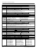
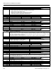
P0310 Rated motor frequency
Min: 12.00 Def: 50.00 or 60.00 Max: 650.00
Level 1
Dependency:
Changeable only when P0010=1 (quick commissioning).
Pole pair number recalculated automatically if parameter is changed.
P0311 Rated motor speed
Min: 0 Def: 0 Max: 40000
Level 1
Dependency:
Changeable only when P0010=1 (quick commissioning).
Setting 0 causes internal calculation of value.
Required for vector control and V/f control with speed controller.
Slip compensation in V/f control requires rated motor speed for correct operation.
Pole pair number recalculated automatically if parameter is changed.
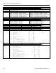
r0313 Motor pole pairs
Min: - Def: - Max: -
Level 3
Value:
r0313=1 : 2-pole motor r0313=2 : 4-pole motor, etc.
Dependency:
Recalculated automatically when P0310 (rated motor frequency) or P0311 (rated motor speed) is changed.
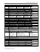
P0340 Calculation of motor parameters
Min: 0 Def: 0 Max: 4
Level 2
Data:
Calculates various motor parameters, including:
• Motor weight P0344 (Level 3)
• Magnetization time P0346 (Level 3)
• Demagnetization time P0347 (Level 3)
• Stator resistance P0350 (Level 2)
• Reference frequency P2000 (Level 2)
• Reference current P2002 (Level 3).
Enum:
0=No calculation
1=Complete parameterization
2=Calc. equivalent circuit data
3=Calc. V/f and vector control
4=Calc. only controller setting
Note:
This parameter is required during commissioning to optimize inverter performance.
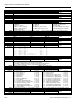
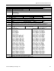
P0350 Stator resistance (line-to-line)
Min: 0.00001 Def: 4.0 Max: 2000.0
Level 2
Data:
Stator resistance value in [Ohms] for connected motor (from line-to-line). The parameter value includes the cable
resistance. There are three ways to determine the value for this parameter:
1. Calculate using P0340=1 (data entered from rating plate) or P3900=1, 2 or 3 (end of quick commissioning)
2. Measure using P1910=1 (motor data identification-value for stator resistance is overwritten)
3. Measure manually using an Ohmmeter.
Note:
Since measured line-to-line, this value may appear to be higher (up to two times higher) than expected.
The value entered in P0350 (stator resistance) is the one obtained by the method last used.
r0395
CO: Total stator resistance [%]
Min: - Def: - Max: -
Level 3
P0304 (rated motor voltage)
Note:
100% means: Z
rated motor
*
P0305 (rated motor current)
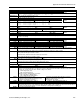
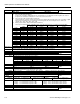
P0400 Select encoder type
Min: 0 Def: 0 Max: 12
Level 3
Settings:
0=Disabled
1=Single channel encoder
2=Quadrature encoder without zero pulse
3=External pulse train
12=Quadrature encoder with zero pulse
Note:
The term quadrature in settings 2 and 12 refers to 2 periodic functions separated by a quarter cycle or 90 degrees.
P0409 Pulses per second at rated frequency
Min: 1 Def: 1024 Max: 20000
Level 2
Enum:
0=Constant torque 1=Pumps and fans
P0501[2] Type of sensor
Min: 0 Def: 0 Max: 51
Level 2
Setting:
0=No sensor selected
1=Sensor type QBE620 P1
2=Sensor type QBE620 P10
3=Sensor type QBE620 P16
4=Sensor type QBE620 P25
5=Sensor type QBE620 P40
6=Sensor type QBE620 P4
7=Sensor type QBE620 P5
8=Sensor type QBE621 P10U
9=Sensor type QBE621 P25U
10=Sensor type QBE63 DP01
11=Sensor type QBE63 DP02
12=Sensor type QBE63 DP05
13=Sensor type QBE63 DP1
14=Sensor type QBE63 DP4
15=Sensor type 0 to 1 INCH WC
16=Sensor type 0 to 2 INCH WC
17=Sensor type 0 to 2.5 INCH WC
18=Sensor type 0 to 3 INCH WC
19=Sensor type 0 to 5 INCH WC
20=Sensor type 0 to 10 INCH WC
21=Sensor type 0 to 10 PSI
22=Sensor type 0 to 15 PSI
23=Sensor type 0 to 25 PSI
24=Sensor type 0 to 30 PSI
25=Sensor type 0 to 50 PSI
26=Sensor type 0 to 60 PSI
27=Sensor type 0 to 100 PSI
28=Sensor type 0 to 150 PSI
29=Sensor type AI Ni 1000:
-58 to 302F (-50 to 150C)
Index:
P0501[0] : IN000 Analog input 1. P0501[1] : IN001 Analog input 2.