
Technical data


Appendix A: Parameter Reference List
Siemens Building Technologies, Inc. 109
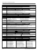
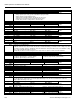
P0779[2] Value x2 of DAC scaling
Min: -99999.0 Def: 100.0 Max: 99999.0
Level 2
Index:
P0779[0] : IN000 Analog output 1 (DAC 1) P0779[1] : IN001 Analog output 2 (DAC 2)
Dependency:
Affects P2000 to P2003 (referency frequency, voltage, current or torque) depending on which setpoint is to be generated.
P0780[2] Value y2 of DAC scaling
Min: 0 Def: 20 Max: 20
Level 2
Index:
P0780[0] : IN000 Analog output 1 (DAC 1) P0780[1] : IN001 Analog output 2 (DAC 2)
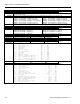
P0781[2] Width of DAC deadband
Min: 0 Def: 0 Max: 20
Level 2
Index:
P0781[0] : IN000 Analog output 1 (DAC 1) P0781[1] : IN001 Analog output 2 (DAC 2)
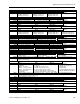
P0809[3] Copy Command Data Set
Min: 0 Def: 0 Max: 2
Level 2
Index:
P0809[0] : Copy from CDS P0809[1] : Copy to DDS P0809[2] : Start copy
Note:
Start value in index 2 is automatically reset to ’0’ after execution of function
P0810 BI: CDS bit 0 (Local/Remote)
Min: 0:0 Def: 718:0 Max: 4095:0
Level 2
Note:
Bit 1 is also relevant for BICO data set selection.
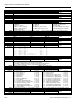
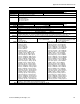
P0918 CB address
Min: 0 Def: 3 Max: 65535
Level 2
Data:
Defines address of CB (communication board) or address of the other option modules.
There are two ways to set the bus address:
1. via DIP switches on the PROFIBUS module
2. via a user-entered value
Note:
Possible PROFIBUS settings:
1 ... 125
0, 126, 127 are not allowed
The following applies when a PROFIBUS module is used:
DIP switch =0 Address defined in P0918 (CB address) is valid
DIP switch not=0 DIP switch setting has priority and P0918 indicates DIP switch setting.
P0927 Parameter changeable via
Min: 0 Def: 15 Max: 15
Level 2
Example:
b-- n n" (bits 0, 1, 2 and 3 set) in the default setting means that parameters can be changed via any interface.
"b-- r n" (bits 0, 1 and 3 set) would specify that parameters can be changed via PROFIBUS/CB, BOP and USS on COM link
(RS485 USS) but not via USS on BOP link (RS232)
Bit Fields:
Bit00 PROFIBUS/CB 0 NO, 1 YES
Bit01 BOP 0 NO, 1 YES
Bit02 USS on BOP link 0 NO, 1 YES
Bit03 USS on COM link 0 NO, 1 YES
Details:
The seven-segment display is explained in the "Introduction to MICROMASTER System Parameters".
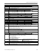
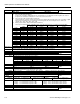
r0947[8] Last fault code
Min: - Def: - Max: -
Level 2
Data:
Displays fault history, where:
"F1" is the first active fault (not yet acknowledged).
"F2" is the second active fault (not yet acknowledged).
"F1e" is the occurrence of the fault acknowledgement for F1 and F2.
This moves the value in the 2 indices down to the next pair of indices, where they are stored. Indices 0 and 1 contain the
active faults. When faults are acknowledged, indices 0 and 1 are reset to 0.
Example:
If the inverter trips on undervoltage and then receives an external trip before the undervoltage is acknowledged, you will
obtain:
Index 0=3 Undervoltage
Index 1=85 External trip
Whenever a fault in index 0 is acknowledged (F1e), the fault history shifts as indicated in the diagram above.
Index:
r0947[0] : Recent fault trip --, fault 1
r0947[1] : Recent fault trip --, fault 2
r0947[2] : Recent fault trip -1, fault 3
r0947[3] : Recent fault trip -1, fault 4
r0947[4] : Recent fault trip -2, fault 5
r0947[5] : Recent fault trip -2, fault 6
r0947[6] : Recent fault trip -3, fault 7
r0947[7] : Recent fault trip -3, fault 8
Dependency:
Index 2 used only if second fault occurs before first fault is acknowledged.