
Technical data


SED2 Operation & Maintenance Manual
20 Siemens Building Technologies, Inc.
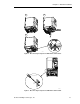
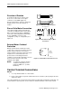
Direction of Rotation
To change the direction of rotation of the
motor, cross-connect two of the output
conductors on the SED2 (Figure 15).
Reverse Output Phase Sequence parameter
P1820 can also reverse the direction of
rotation.
5192V01
M
M
SED2
U
V
W
U
V
W
SED2
U
V
W
U
V
W
Figure 15. Direction of Motor Rotation.
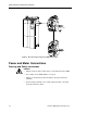
Star or Delta Motor Connection
The required supply voltage and method of
connection are indicated on the motor rating
plate. In general, larger motors (400/690V)
connect in a delta configuration and smaller
motors (230/400V) connect in a star
configuration (or wye “Y” configuration). See
Figure 16.
U
1
V
1
W
1
W
2
U
2
V
2
U
1
V
1
W
1
W
2
U
2
V
2
Motor terminal board
5192Z30en
Figure 16. Delta and Star (Wye, Y) Motor
Connections.
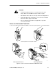
External Motor Overload
Protection
During operation below nominal speed, the
cooling effect of the fans mounted to the motor
shaft is reduced. Therefore, most motors
require derating if operated continuously at low
frequencies. To ensure that motors are
protected from overheating under these
conditions, mount a PTC temperature sensor to
the motor and connect it to the control
terminals of the SED2.
NOTE: To enable the switch-off function,
set Motor Temperature Sensor
parameter P0601 to 1 (for PTC
thermistor).
14
15
SED2
Control
terminals
5192Z11en
Figure 17. External Motor Overload Protection.
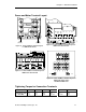
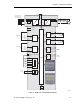
Control Terminal Connections
NOTES:
1. Use only shielded cables for control cables.
2. Route control cables in separate cable trunks at least 7.8 inches (20 cm) away from motor
and power cables
The control terminals are located on the I/O module. The I/O module is identical for all models. It is
located under the operator panel. See the Access to Control Terminals section in this manual.