
Technical data


SED2 Operation & Maintenance Manual
38 Siemens Building Technologies, Inc.
SED2 Basic Functions
Digital Inputs
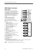
Stand-alone operation of the SED2 requires
external switch-on and switch-off arrangements.
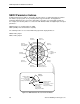
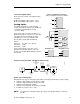
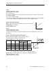
The SED2 supports six-digital inputs, DIN1
through DIN6 (Figure 25), and can be extended
to eight-digital inputs (DIN7 and DIN8) by using
two analog inputs (AIN1 and AIN2). You can
program the function of the digital inputs as
required.
Parameter Settings for DIN1 to 6
(or DIN1 to 8) (Commissioning)
P0701 to P0706, Digital inputs 1 to 6
The available settings for each digital input is as
follows:
5
6
7
9
16
17
28
PNP
NPN
DIN1
DIN2
DIN3
DIN4
DIN5
DIN6
8
or
Isolated +24 V (Output)
Isolated 0 V (Output)
DC- isolated
5192Z17en
Figure 25. SED2 Digital Inputs 1 through 6.
0 Digital input disabled.
1 ON/OFF1 – Off as defined via Ramp-Down
Time parameter P1121.
2 ON + change direction of rotation/OFF1.
3 OFF2 – coast to standstill.
4 OFF3 – faster ramp-down (quick stop =
ramp-down at power limit).
9 Fault acknowledgement.
10 JOG right.
11 JOG left.
12 Reverse direction of rotation.
13 Motor potentiometer (MOP) higher
(increased frequency).
14 Motor potentiometer (MOP) lower (reduced
frequency).
15 Fixed setpoint (direct selection).
16 Fixed setpoint (direct selection + ON).
17 Fixed setpoint (binary-coded selection + ON).
25 Enable DC braking.
26 Enable Essential Service.
Function
DIN1
P0701
Function
DIN2
P0702
Function
DIN3
P0703
Function
DIN4
P0704
Function
DIN5
P0705
Function
DIN6
P0706
r0722
Status of
Digital Inputs
P0725
0 = active low
1 = active high
27 Enable PID controller.
29 External trip.
33 Disable additional frequency setpoint.
99 Enable BICO parameter setting (see the description of BICO in the SED2 Operation &
Maintenance Manual Addendum, Document No. 125-3205.)
NOTE: Setting 99 (BICO) is intended for experienced users only.