
Technical data


Chapter 6 – Programming
Siemens Building Technologies, Inc. 39
Factory settings:
P0701 1 ON/OFF1 – Off as defined via Ramp-Down Time parameter P1121.
P0702 12 Reverse (change of rotation).
P0703 9 Fault acknowledgement.
P0704 15 Fixed setpoint (direct selection).
P0705 15 Fixed setpoint (direct selection).
P0706 15 Fixed setpoint (direct selection).
Index: Example for P0701, applies also to parameters P0702 to P0706.
P0701[0]: IN000 (AUTO)=1st command data set (CDS).
P0701[1]: IN001 (HAND)=2nd command data set (CDS).
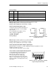
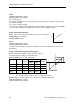
P0707 to P0708, Analog inputs 1 and 2
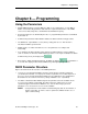
If required, Parameters P0707 and P0708 can
reconfigure Analog Inputs 1 and 2 as Digital
Inputs 7 and 8.
The following limit values apply to analog
inputs configured as digital inputs:
9GF 2IILQDFWLYH
9GF 2QDFWLYH
Factory setting: 0
1
2
3
4
DIN7
1
2
11
12
DIN8
5192Z15
Figure 26. Connection of Analog Inputs 1 and 2
as Digital Inputs 7 and 8.
Index: Example for P0707, applies also to parameter P0708.
P0707[0]: IN000 (AUTO)=1st command data set (CDS).
P0707[1]: IN001 (HAND)=2nd command data set (CDS).
P0725, Operating mode (NPN or PNP) for digital inputs
P0725 determines if a logic 0 or 1 enables digital inputs DIN1 through DIN6 as follows:
0=NPN mode=Active low (logic 0)
1=PNP mode=Active high, (logic 1) factory setting
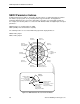
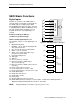
r0722, Check for signal at digital and analog inputs
Use this parameter to check for the presence
of a signal at the digital and analog inputs.
When an active signal is present, the
associated segment of the display lights.
Figure 27 shows the allocation of each of the
inputs to a specific display segment. Figure 28
shows an example of the display while testing
input signals.
AIN2
AIN1
DIN6 DIN5
DIN4 DIN3
DIN2 DIN1
5192Z14
Figure 27. Allocation of Each Input to a Display
Segment using Parameter r0722.