
Technical data


SED2 Operation & Maintenance Manual
40 Siemens Building Technologies, Inc.
5192Z29
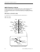
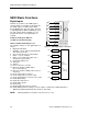
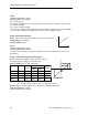
DIN1 = 0
DIN2 = 1
DIN3 = 1
DIN4 = 0
DIN5 = 1
DIN6 = 1
AIN1 = 0
AIN2 = 1
Figure 28. Example of the Display while Testing Input Signals using Parameter r0722.
Digital Outputs
Parameter Settings for DO1 and DO2
P0731 to P0732, Digital outputs 1 and 2
The available settings for each digital output is as follows:
52.0 Drive ready.
52.1 Drive ready to run.
52.2 Drive running.
52.3 Drive fault active.
52.4 OFF2 active.
52.5 OFF3 active.
52.6 Switch on inhibit active.
52.7 Drive warning active.
52.8 Deviation setpoint/actual value.
52.9 PZD control (Process Data Control).
52.A Maximum frequency reached.
52.B Warning: Motor current limit.
52.C Motor holding brake (MHB) active.
52.D Motor overload.
52.E Motor running direction right.
52.F Inverter overload.
53.0 DC brake active.
53.1 Inverter frequency less switch off limit.
53.2 Inverter frequency less minimum frequency.
53.3 Current greater or equal than limit.
53.4 Actual frequency greater comparison
frequency.
53.5 Actual frequency less comparison frequency.
53.6 Actual frequency greater/equal setpoint.
53.7 Voltage less than threshold.
53.8 Voltage greater than threshold.
53.A PID output at lower limit (P2292)
53.B PID output at upper limit (P2291)
Factory settings:
P0731 52.3 Drive fault active
P0732 52.7 Drive running
Index: Example for P0731, applies also to parameter P0732.
P0731[0]: IN000 (AUTO)=1st command data set (CDS).
P0731[1]: IN001 (HAND)=2nd command data set (CDS).
r0747, State of digital outputs
Shows the state of the digital outputs as follows:
Bit 00=Digital output 1 energized (0=no, 1=yes)
Bit 01=Digital output 2 energized (0=no, 1=yes)