
Technical data


Chapter 6 – Programming
Siemens Building Technologies, Inc. 41
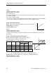
r0747, Invert digital outputs
Shows the inverted state of the digital outputs
as follows:
Bit 00=Invert Digital output 1 (0=no, 1=yes)
Bit 01=Invert Digital output 2 (0=no, 1=yes)
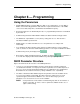
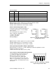
Analog Inputs
The SED2 analog inputs send positioning,
control, and feedback signals to the SED2 and
convert them to digital signals via A/D
converters (ADC).
For accurate and consistent performance of
SED2 analog outputs, if you are not connecting
a NI 1000 sensor then terminals 10 and 4
(NI 1000) must connect to terminal 2 (0V).
Specify analog inputs AIN1 and AIN2 as
follows:
Input level: 0 to 10V, or 0 to 20 mA
Resolution: 10 bit
Read cycle: 10 ms
Set the analog inputs to 0 to 10V, or 0 to
20 mA via the two DIP switches on the I/O
module. See the DIP Switch Settings section in
this manual.
2
3
4
VFD 24V dc POWERED 0-20 mA DEVICE
28
9
mA
Power
(Power consumption cannot exceed 100 mA)
SPEED POTENTIOMETER
1
2
3
10
11
AIN1+
4
Minimum
4.7k
AIN1-
AIN2+
AIN2-
5192Z19
+10 V
0 V
A/D
A/D
2
3
4
EXTERNAL 0-20 mA
3
2
-
+
EXTERNAL 0-10V
Figure 29. SED2 Analog Inputs 1 and 2.
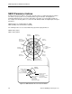
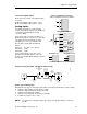
Parameter Settings for AIN1 and AIN2 (Commissioning)
Input
type
SCAL
Input
ADC
deadband
Delay
Loss of signal
ADC
Smoothing time
P0753
1 + 2
Status
r0751
Input value
r0752
1 + 2
Smoothed
value
r0754
1 + 2
Value
+ min/max
r0755
P0761
1 + 2
P0762
1 + 2
P0761
P0757
P0758
P0759
P0760
5192Z20en
P0756, Type of analog input
P0756 defines the type of analog input and enables analog input monitoring. Possible settings:
0 Unipolar voltage input (0 to 10V) (factory setting).
1 Unipolar voltage input with monitoring (0 to 10V).
2 Unipolar current input (0 to 20 mA).
3 Unipolar current input with monitoring (0 to 20 mA).
5 Ni 1000 sensor input (–10 to +10V).
NOTE: The parameter setting must match the setting of the two DIP switches on the I/O
module.