
Technical data

Chapter 9 – Communications
Siemens Building Technologies, Inc. 83
Analog Inputs – Use ANALOG IN 1 (Point 45) and Analog IN 2 (Point 46) to monitor the status
of the drives analog inputs (4 to 20 mA) from the field panel. For example, the chilled water
feedback could be sent to the field panel, calculations performed, and the chilled water valve
control command could be sent from the field panel through the drive and control the drive analog
output over ANALOG OUT 1 (Point 47).
Analog Outputs – Use ANALOG OUT 1 (Point 47) and ANALOG OUT 2 (Point 48) to control an
output (4 to 20 mA) from the field panel.
Loop gains – P GAIN (Point 61), I GAIN (Point 62), and D GAIN (Point 63) are gain parameters
similar to the P and I gains in the APOGEE TECs. The Siemens Building Technologies
representative must program the actual P and I gain constants through the SED2 drive.
Address limitations – Set CRLR ADDRESS (Point 1) to any value from 0 through 99. The
default value for this point is 99.
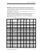
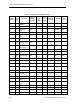
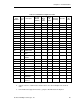
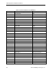
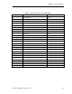
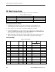
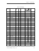
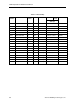
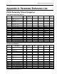
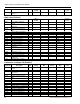
Table 8. Point Database for Application 2722.
Point
Number
Point
Type
Descriptor
Factory
Default
(SI Units)
Engr.
Units
(SI
Units)
Slope
(SI
Units)
Intercept
(SI Units)
On Text
Off
Text
01 LAO CTLR
ADDRESS
99 - 1 0 - -
02 LAO APPLICATION 2722 - 1 0 - -
{03} LAI FREQ
OUTPUT
0 HZ .04 -650 - -
{05} LAI SPEED 0 RPM 1 -16250 - -
{06} LAI CURRENT 0 A 0.5 0 - -
{07} LAI TORQUE 0 NM .02 -3250 - -
{08} LAI ACTUAL
POWER
0 HP/KW .01 0 - -
{09} LAI TOTAL KWH 0 KWH 1 0 - -
{13} LAI DC BUS VOLT 0 V 1 0 - -
{14} LAI REFERENCE 0 HZ .04 -650 - -
{16} LAI RATED PWR 0 HP/KW .01 0 - -
{17} LAI OUTPUT
VOLTS
0 V 1 0 - -
20 LAO OVRD TIME 1 HRS 1 0 - -
{21} LDI FWD.REV FWD - 1 0 REV FWD
{22} LDO CMD
FWD.REV
FWD - 1 0 REV FWD
{23} LDI STOP.RUN STOP - 1 0 RUN STOP
{24} LDO CMD
STP.STRT
STOP - 1 0 START STOP
{25} LDI AT MAX
FREQ
NO - 1 0 MAX NO