
Data Sheet for Product


s Industry, Inc.
Building Technologies Division
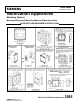
Mounting Notes
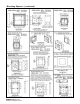
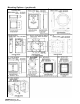
Caution: The mounting options figures show
the maximum number of field
wires (conductors) that can enter
the back box used with each
mounting option.
If these limits are exceeded, there may be
insufficient space in the back box to
accommodate the field wires and stresses
from the wires could damage the product.
Although the limits shown for each
mounting option comply with the National
Electrical code (NEC), Siemens recommends
use of the largest backbox option and the use
of approved field wires whenever possible to
provide additional wiring room for easy
installation and minimum stress on the
product from wiring.
Caution: Check that the installed product
will have sufficient clearance and
wiring room prior to installing
back-boxes and conduit, especially
if sheathed multi-conductor cable
or 3/4- inch conduit fittings are
used.
1. Mounting hardware for each mounting
option is supplied.
2. Conduit entrances to the back box
should be selected to provide
sufficient wiring clearance for the
installed product.
3. When extension rings are required,
conduit should enter through the back
box, not the extension ring. Use Steel
City
#
53151 (1-1/2” deep) or
#
53171
(2-1/8” deep) extension rings (as noted
in the mounting options) or equal with
the same cut-out area.
4. When terminating field wires, do not
use more lead length than required.
Excess lead length could result in
insufficient wiring space for the
appliance.
5. Use care and proper techniques to
position the field wires in the back box so
that they use minimum space and produce
minimum stress on the product. This is
especially important for stiff, heavy gauge
wires and wires with thick insulation or
sheathing.
6. Do not pass additional wires (used for other
than the appliance) through the back box
“unless the back box is of a sufficient size
to permit additional wiring as described in
NEC 314.16 (B)”. Such additional wires
could result in insufficient wiring space for
the appliance.
Note: Due to continuous development of
our products, specifications and
offerings are subject to change without
notice, in accordance with Siemens
Industry, Inc. standard terms and
conditions.
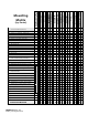
Back Box Mounting
Siemens Horizontal, Wall-Mounted Strobe
Appliances NFPA-72 (2007)
7.5.4.1* ─ Wall-mounted appliances shall be
mounted such that the entire lens is
not less than 80 inches (203 cm.) and
not greater than 96 inches (244 cm.)
above the finished floor or at the
mounting height specified using the
performance-based alternative 7.5.4.5.
7.5.4.2 ─ Where low ceiling heights do not
permit mounting at a minimum of
80 inches (203 cm.), visible
appliances shall be mounted
within 6 inches (15 cm.) of the
ceiling.
The room size covered by a strobe
of a given value shall be reduced
by twice the difference between
the minimum mounting height of
80 inches (203 cm.) and the
actual, lower mounting height.