Preface SIMATIC Time synchronization (V7.1) SIMATIC Process Control System PCS 7 Time synchronization (V7.
Legal information Legal information Warning notice system This manual contains notices you have to observe in order to ensure your personal safety, as well as to prevent damage to property. The notices referring to your personal safety are highlighted in the manual by a safety alert symbol, notices referring only to property damage have no safety alert symbol. These notices shown below are graded according to the degree of danger.
Table of contents 1 Preface ...................................................................................................................................................... 7 2 Fundamentals............................................................................................................................................ 9 3 2.1 Using time synchronization in PCS 7.............................................................................................9 2.
Table of contents 5 Configuring time synchronization ............................................................................................................. 49 5.1 Introduction ................................................................................................................................. 49 5.2 5.2.1 5.2.2 Setting the time displayed ...........................................................................................................
Table of contents 6 5.11 How to synchronize PC stations using NTP mode ....................................................................121 5.12 5.12.1 5.12.2 Configuring redundant PCS 7 systems......................................................................................122 How to configure time synchronization of OS servers with a redundant communication module and external clock .........................................................................................................
Table of contents 6 Time synchronization (V7.
1 Preface Purpose of this documentation The time synchronization documentation provides support for the configuration and commissioning of the "time synchronization" function in a PCS 7 plant.
Preface Target group and benefit This documentation is intended for personnel working in the fields of sales, planning, and configuration: Target group Using the documentation Sales Sales personnel give clear advice to their • customers on implementing the "time • synchronization" function in a PCS 7 plant.
2 Fundamentals 2.1 Using time synchronization in PCS 7 Introduction Plants in which Process Control Systems are used contain numerous components that exchange data. Most plants require time synchronization for controlling processes and information. There are additional requirements in terms of the documentation of event sequences. If the timing of components in the overall system is not synchronized, these tasks can only be supported by the internal clock of the individual components.
Fundamentals 2.1 Using time synchronization in PCS 7 Time synchronization Time synchronization means that one system component (time master) provides a precise time for all the other components (time slaves). The time information (date and time) can either be distributed by the time master, or be requested by the time slaves. For the overall task, all components within the system must evaluate this time information.
Fundamentals 2.2 Time synchronization options for PCS 7 components 2.2 Time synchronization options for PCS 7 components Time synchronization for PCS 7 components The table below shows the PCS 7 components for which time synchronization is possible: Station Time synchronization Operator station • • Via the terminal bus Via the plant bus • • Via the operating system • BATCH station For further information, refer to the section ...
Fundamentals 2.3 Time displayed in PCS 7 2.3 Time displayed in PCS 7 Coordinated Universal Time (UTC) Coordinated Universal Time (UTC) is an international time basis that takes as its precedent the precision of atomic clocks. UTC refers to the Greenwich prime meridian in London. UTC does not take daylight saving time into account. Local time East of the prime meridian, one or more hours is added to the universal time measured in Greenwich, depending on the distance in question.
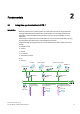
Fundamentals 2.4 Time synchronization in distributed PCS 7 plants 2.4 Time synchronization in distributed PCS 7 plants Introduction PCS 7 supports system configurations where subcomponents are installed at different locations, or even in different time zones. An example would be the installation of an automation system and an operator station at different locations. The time must be synchronized for the entire PCS 7 plant in order to optimize the sequence of all the processes.
Fundamentals 2.4 Time synchronization in distributed PCS 7 plants If the times for the components of a distributed PCS 7 plant are synchronized, all of the processes will run in correct chronological order and will be archived correctly. 2SHUDWRU VWDWLRQ %HUOLQ 0HVVDJHV 7LPH V\QFKURQL]DWLRQ $XWRPDWLRQ V\VWHP 14 Time synchronization (V7.
Fundamentals 2.4 Time synchronization in distributed PCS 7 plants Rules for configuring distributed PCS 7 plants Since PCS 7 plants generally operate on the basis of UTC internally, their specific components can be distributed on a global scale. In order to safeguard the interplay of components - even across different time zones - please observe the following: ● Use UTC as the common time base in all PCS 7 plants. All plant components running with UTC will display the same time after time synchronization.
Fundamentals 2.5 Central plant clock 2.5 Central plant clock Using a central plant clock You should always synchronize all Process Control Systems using either a precise time or a standard time. In the case of PCS 7 plants, we recommend performing synchronization by means of a central plant clock. The central plant clock manages the time centrally for the entire plant and synchronizes all of the other plant components via their interfaces.
Fundamentals 2.6 Time levels for a PCS 7 plant (stratum) 2.6 Time levels for a PCS 7 plant (stratum) Introduction Time synchronization of a system involves one component synchronizing the next component by forwarding a time message frame. Forwarding time message frames will result in time delays. You should make allowances for this fact when setting up a PCS 7 plant.
Fundamentals 2.6 Time levels for a PCS 7 plant (stratum) Time synchronization using strata The following figure shows an example of time synchronization using strata: 8QLW 'RPDLQ 8QLW 8QLW 'RPDLQ 7LPH VLJQDO *36 '&) 'RPDLQ 8QLW 6,&/2&.
Fundamentals 2.6 Time levels for a PCS 7 plant (stratum) Rules for planning a PCS 7 plant taking strata into account Please observe the following rules when planning time synchronization, to ensure that the time deviation of the time master is not too high in relation to the components in the lowest stratum: ● Use as few strata as possible. ● In most cases using a maximum of four strata is recommended. ● Use the same strata for the same structure elements.
Fundamentals 2.7 Time synchronization in PCS 7 - mode of operation 2.7 Time synchronization in PCS 7 - mode of operation 2.7.1 Time master and time slave Introduction To ensure that all Process Control System components operate with as precise a time as possible, one system component must be the time source for all other components. The precise time must be permanently available and be used for synchronization on a cyclical basis (synchronization interval).
Fundamentals 2.7 Time synchronization in PCS 7 - mode of operation Function of the cooperative time master The following process is initiated at the startup of a PC station that is configured as a cooperative time master. A time message frame must be received within the wait time once the PC station has powered up. The wait time amounts to four times the set synchronization interval.
Fundamentals 2.7 Time synchronization in PCS 7 - mode of operation 2.7.2 Time sources for a PCS 7 plant Overview In PCS 7 plants, it is necessary to define which component is capable of providing the plant with a satisfactory time in terms of quality. You can use either internal or external time sources for this purpose. Suitability External time source Internal time source External time sources provide an ultraprecise time and are suitable for all plant configurations.
Fundamentals 2.7 Time synchronization in PCS 7 - mode of operation 2.7.3 Example of the time synchronization sequence Introduction The example below shows an example of time synchronization in PCS 7, based on configurations for an OS. Note The individual components are identified in the figures below as follows: • Dashed line starting at a component Components with red dashed lines leading away from them are time masters in this network.
Fundamentals 2.7 Time synchronization in PCS 7 - mode of operation Time synchronization with central plant clock and cooperative time master In the image below, the SICLOCK is the time master for the plant. The OS server pair (of redundant OS servers) and the automation systems are configured as time slaves of the SICLOCK. The OS server pair is the cooperative time master on the plant bus. One of the OS servers assumes the time master function if the connection to the SICLOCK fails.
Fundamentals 2.8 Network environment of a PCS 7 plant 2.8 Network environment of a PCS 7 plant 2.8.1 Overview Network configuration for time synchronization in PCS 7 The sections that follow provide examples of network configurations for time synchronization in PCS 7.
Fundamentals 2.8 Network environment of a PCS 7 plant 2.8.2 Legend for figures used in this documentation Legend for configuration figures used in this documentation Note The individual components are identified in the figures below as follows: • Dashed line starting at a component Components with red dashed lines leading away from them are time masters in this network. • Arrow pointing to a component Components to which an arrow is pointing are time slaves in this network.
Fundamentals 2.8 Network environment of a PCS 7 plant 2.8.3 Network environment within a domain Central plant clock The SICLOCK TC 400 is particularly suitable for operation as a central plant clock within a domain, as the SICLOCK has four independent Ethernet interfaces. Structure The following figure illustrates the recommended configuration for a PCS 7 plant in a Windows domain with a central time clock: 6,&/2&.
Fundamentals 2.8 Network environment of a PCS 7 plant 2.8.4 Network environment within a work group Central plant clock The SICLOCK TC 400 is suitable for operation as a central plant clock. Structure The following figure illustrates the recommended configuration for a PCS 7 plant in a work group with a central time clock: 26 FOLHQWV 7HUPLQDO EXV 6,&/2&.
Fundamentals 2.8 Network environment of a PCS 7 plant 2.8.5 Network environment in redundant, high-availability networks Introduction Always install redundant networks in a PCS 7 plant as a precaution against production losses caused by failures in the network connections. This will ensure that communication via the redundant network will remain intact if an area of the terminal bus fails. The domain controllers synchronize one another's time on the basis of Windows mechanisms.
Fundamentals 2.8 Network environment of a PCS 7 plant Time synchronization in redundant, high-availability networks The time is synchronized as follows: ● SICLOCK supplies the exact time. ● The domain controller, terminal bus, and plant bus are synchronized by means of the SICLOCK. ● The domain controllers act as time masters. ● The OS servers actively fetch the time from the domain controller. 30 Time synchronization (V7.
Fundamentals 2.8 Network environment of a PCS 7 plant 2.8.6 Network environment on separate networks with one central plant clock Central plant clock If you need to synchronize more than four networks using a single central plant clock (e.g. SICLOCK TC 400) as the time source, you can use suitable switches to provide the time within the individual networks. The switch is only used to distribute time message frames. The remaining plant structure is identical to the relevant plant configuration.
Fundamentals 2.8 Network environment of a PCS 7 plant Additional information ● (http://www.siemens-edm.de/fileadmin/Application_Notes/App_Note_0002.pdf) ● Configuration Manual Industrial Communication; Industrial Ethernet Switches; SCALANCE X-300; SCALANCE X-400 ● User Manual SIMATIC NET; Industrial Ethernet OSM/ESM; Industrial Ethernet OSM/ESM 32 Time synchronization (V7.
Configurations for time synchronization of a PCS 7 plant 3.1 3 Overview of recommended configurations Introduction Various techniques are possible for time synchronization. The structure of a PCS 7 plant with time synchronization requires careful planning in order to prevent any undesired results. Use one of the following configurations to support you in planning your PCS 7 plant.
Configurations for time synchronization of a PCS 7 plant 3.2 Rules for time synchronization in PCS 7 3.2 Rules for time synchronization in PCS 7 Rules ● A network may only contain one active time master. ● Time synchronization with an external time source (e.g. GPS, DDF 77) is required if the time within the PCS 7 plant is to match the local time. ● Central plant clocks (synchronized with an external time source wherever possible) are high-grade internal time sources for PCS 7 plants.
Configurations for time synchronization of a PCS 7 plant 3.2 Rules for time synchronization in PCS 7 V5-compatible mode Note Contact Customer Support if you want to use time synchronization in V5-compatible mode. Further information ● Section "Time synchronization in distributed PCS 7 plants (Page 13)" ● Documentation Process Control System PCS 7; Released modules Time synchronization (V7.
Configurations for time synchronization of a PCS 7 plant 3.3 Configurations for time synchronization in a work group 3.3 Configurations for time synchronization in a work group 3.3.1 Configuration of time synchronization with central time master in a work group Configuration The following figure is a schematic representation of how time synchronization of a work group with central time master should ideally be configured. 26 FOLHQWV 7HUPLQDO EXV 6,&/2&.
Configurations for time synchronization of a PCS 7 plant 3.3 Configurations for time synchronization in a work group Time synchronization on the plant bus ● Time master is the SICLOCK connected to the plant bus as the central plant clock. It sends a high-precision broadcast time signal on the plant bus. Time synchronization is set in SIMATIC mode. ● The OS servers are configured as what are known as cooperative time masters.
Configurations for time synchronization of a PCS 7 plant 3.3 Configurations for time synchronization in a work group 3.3.
Configurations for time synchronization of a PCS 7 plant 3.3 Configurations for time synchronization in a work group Time synchronization on the plant bus Configuring the automation systems: ● The automation system with standard CPU (without integrated Ethernet interface) is configured for operation as a time slave. ● The SIMATIC PCS 7 BOX and SIMATIC PCS 7 AS RTX are configured.
Configurations for time synchronization of a PCS 7 plant 3.4 Configuration for time synchronization in a Windows domain 3.4 Configuration for time synchronization in a Windows domain 3.4.1 Configuration of time synchronization with central time master in a Windows domain with a hierarchy Introduction In a Windows domain, you should synchronize the terminal bus and the plant bus directly using the central plant clock.
Configurations for time synchronization of a PCS 7 plant 3.4 Configuration for time synchronization in a Windows domain Time synchronization on the terminal bus ● Active time master: The time master is the domain controller (DC), which is parameterized as the main structure master and/or the PDC emulator (usually the first domain controller installed). ● Time source: The domain controller receives the time from the SICLOCK central plant clock.
Configurations for time synchronization of a PCS 7 plant 3.4 Configuration for time synchronization in a Windows domain 3.4.2 Configuration of time synchronization with central time master in a Windows domain with a hierarchy Configuration The figure below illustrates the recommended configuration of a PCS 7 plant with time synchronization and without a central time master in a Windows domain.
Configurations for time synchronization of a PCS 7 plant 3.4 Configuration for time synchronization in a Windows domain Time synchronization on the plant bus ● Synchronization is configured for all automation systems on the plant bus. ● The OS servers receive the time signal via the terminal bus from the authorized domain controller (PDC operation master). ● Each OS server on the plant bus is configured as a cooperative time master.
Configurations for time synchronization of a PCS 7 plant 3.4 Configuration for time synchronization in a Windows domain 3.4.3 Configuration of the time synchronization in a Windows domain with multiple hierarchies Configuration The following figure shows a sample configuration for time synchronization in a Windows domain with multiple hierarchies: 8QLW 'RPDLQ 8QLW 8QLW 'RPDLQ 'RPDLQ 7LPH VLJQDO 6,&/2&.
4 Planning time synchronization 4.1 Selecting the time master Selecting the time master On a time-synchronous PCS 7 plant, you require a time master to which the additional plant components can be synchronized. The table below lists the components that are used as time masters, depending on the network environment: Time master SICLOCK OS server With time source ... Provides the time via ... Time master forwards the time to... Forwards the time to ...
Planning time synchronization 4.2 Selecting the central plant clock 4.2 Selecting the central plant clock Introduction You should always synchronize all automation processes using a standard time. In the case of PCS 7 plants, we recommend performing synchronization by means of a central plant clock. The central plant clock controls the time for the entire PCS 7 plant, and synchronizes all other plant components via their interfaces.
Planning time synchronization 4.2 Selecting the central plant clock Representation of the SICLOCK variants The following figures show a SICLOCK TC 400: The following figure shows a SICLOCK TM: The following figure shows a SICLOCK TS: Further information ● Information concerning central plant clocks on the Internet: (http://www.siemens-edm.de/anlagen_zentraluhren.0.html?&L=2) Time synchronization (V7.
Planning time synchronization 4.2 Selecting the central plant clock 48 Time synchronization (V7.
Configuring time synchronization 5.1 5 Introduction Components To synchronize the time of your plant, it is necessary to configure all network nodes for time synchronization. To do this configure the following components depending on configuration: ● Time receivers If synchronizing the time using an external time source, you must configure the time recipient for a central plant clock. ● Operator station Configure the OS server(s) and the OS clients.
Configuring time synchronization 5.1 Introduction Time synchronization modes The time synchronization mode is activated when configuring time synchronization.
Configuring time synchronization 5.2 Setting the time displayed 5.2 Setting the time displayed 5.2.1 How to configure the operator station display Introduction You configure the time display for the operator station process mode on the engineering station. You can select the "Local time zone", for example, in the "Time base for time display in runtime" parameter. Requirement ● You must configure the time display on the engineering station before you load the OS. Procedure 1.
Configuring time synchronization 5.2 Setting the time displayed 4. Select the "Parameters" tab. Figure 5-1 52 Example: Setting for the "Local time zone" Time synchronization (V7.
Configuring time synchronization 5.2 Setting the time displayed 5. Select "The PLC is is set to coordinated universal time (UTC) (preferred setting)" check box in the "PLC clock setting" group. 6. Select the required time mode from the "Time base for time display in runtime" drop-down list box.
Configuring time synchronization 5.2 Setting the time displayed 5.2.2 How to convert the local time zone and daylight saving time parameters Introduction You can convert the time displayed on the OS in process mode. Rules ● If operating a plant across several time zones with different daylight saving time and standard time settings, you should also use the harmonized UTC time for the time display on the operator station. You therefore have a uniform basis for process analysis at all plant units.
Configuring time synchronization 5.2 Setting the time displayed 4. Select the check box "Automatically adjust clock for daylight saving changes". 5. Click "OK". Result All time information for the operator station will be output in the local time of the selected time zone, including daylight saving time changes, and it will be converted at the correct point in time. Time synchronization (V7.
Configuring time synchronization 5.3 Overview of configuration steps, depending on the configuration 5.3 Overview of configuration steps, depending on the configuration 5.3.
Configuring time synchronization 5.3 Overview of configuration steps, depending on the configuration 5.3.
Configuring time synchronization 5.3 Overview of configuration steps, depending on the configuration 5.3.
Configuring time synchronization 5.3 Overview of configuration steps, depending on the configuration 5.3.
Configuring time synchronization 5.4 Commissioning a central plant clock 5.4 Commissioning a central plant clock 5.4.1 Commissioning the SICLOCK TC 400 Requirement To configure the SICLOCK TC 400, the Java runtime software is required. Only install the Java runtime software for accessing the SICLOCK TC 400 on an engineering station or a separate PC station (not on components that are involved in process mode). The Java runtime software is supplied on a CD together with the SICLOCK TC 400.
Configuring time synchronization 5.4 Commissioning a central plant clock Set the basic parameters on the SICLOCK TC 400 The direct parameter settings on the SICLOCK TC 400 are required as basic parameters for connection to the network only. 1. Press the "Setup" button on the SICLOCK TC 400. 2. Enter the password and then press "OK".
Configuring time synchronization 5.4 Commissioning a central plant clock Configuring the SICLOCK TC 400 1. Connect the SICLOCK TC 400 to the network. (For example, connect Ethernet port ETH1 of the SICLOCK TC 400 to the terminal bus) 2. Open Internet Explorer on a PC. Enter the network address of the SICLOCK TC 400 in the input field (e.g. Port:ETH1 = address 192.168.1.10). 3. In the configuration portal area, click the "SICLOCK TC 400 configuration tool" link. The configuration tool opens. 4.
Configuring time synchronization 5.4 Commissioning a central plant clock Note For the purpose of time synchronization on the plant bus, activate SIMATIC mode separately for each Ethernet port. The settings can be password-protected. You will find additional information on this topic in the SICLOCK; SICLOCK TC 400 Operating Instructions. Loading the configuration to the SIMATIC TC 400 This step is only necessary if the configuration is carried out offline.
Configuring time synchronization 5.4 Commissioning a central plant clock 5.4.
Configuring time synchronization 5.4 Commissioning a central plant clock Assigning parameters to the SICLOCK TM/TS for NTP mode Make the settings directly on the SICLOCK TM/TS. 1. Call the parameters of the SICLOCK TM/TS. 2. Set parameter 338/6A Ethernet to "On." 3. Select an unassigned IP address on your plant bus and configure this at parameter 343/6A of the SICLOCK TM/TS. 4. Enter "any/unicast" for parameter 550/6F "SNTP-Server". Note Check the parameter settings if necessary.
Configuring time synchronization 5.4 Commissioning a central plant clock 5.4.3 Commissioning GPS receivers Introduction The GPS receiver determines the UTC via the satellite-based GPS system (Global Positioning system). Due to the country-specific installation of Windows on the OS the sent UTC is converted to the time valid in the respective country. For reception of the precise time reception of the signal from one of the 24 satellites suffices.
Configuring time synchronization 5.4 Commissioning a central plant clock Wiring ● The following figure shows how the GPS receiver is connected to the SICLOCK TC 400: 6,&/2&. *36 6,&/2&. 7& ; 5$',2 &/2&. *1' 5$',2 &/2&. $ 5$',2 &/2&. % 5$',2 &/2&. $ 5$',2 &/2&. % 0D[ P CAUTION The GPS receiver may only be used as an active radio clock. The GPS receiver will be destroyed if operated as a passive radio clock.
Configuring time synchronization 5.4 Commissioning a central plant clock Aligning the GPS antenna Proceed as follows: 1. Install the GPS antenna. 2. Align the antenna vertically to the sky. With other angles the synchronization can fail temporarily because a satellite is not in the reception window. Note Do not install the GPS antenna at locations where there is a risk of lightning strikes occurring. If nothing else is possible, attach the GPS antenna to the inside of high windows.
Configuring time synchronization 5.4 Commissioning a central plant clock 5.4.4 Commissioning the DCF 77 receiver Introduction DCF 77 is an officially approved standard time in Germany. The DFC 77 radio signal is limited to a radius of 800 km around the Frankfurt/Main area. In regions where the DCF 77 radio signal cannot be received, use of a GPS receiver is recommended. You need a DCF 77 receiver to use this radio signal for time synchronization of your PCS 7 plant.
Configuring time synchronization 5.4 Commissioning a central plant clock Wiring The following figure shows how to wire the SICLOCK TC 400 to a DCF 77 receiver: 6,&/2&. '&)56 6,&/2&. 7& ; 5$',2 &/2&. *1' 5$',2 &/2&. $ 5$',2 &/2&. % 5$',2 &/2&. $ 5$',2 &/2&. % 0D[ P Align the antenna To optimize the alignment of your DCF 77 receiver, proceed as follows: 1. Align the DCF 77 receiver so that the control LED flashes at intervals of one second. 2.
Configuring time synchronization 5.5 Configuring the time synchronization of the OS 5.5 Configuring the time synchronization of the OS 5.5.
Configuring time synchronization 5.5 Configuring the time synchronization of the OS 5.5.2 How to set time synchronization on an OS in a work group with central time master Example configuration 26 FOLHQWV 7HUPLQDO EXV 6,&/2&. 26 VHUYHU 0 26 VHUYHU 0 3ODQW EXV $6 $6 Requirements ● The "Time tracking" option must be activated in the configuration console for the network adapter of the OS server.
Configuring time synchronization 5.5 Configuring the time synchronization of the OS 3. Select Open from the shortcut menu. The "Time Synchronization" dialog box opens. 4. Select the "Synchronization via plant bus (master, slave)" check box. 5. From the "Access point 1" drop-down list box, select the network adapter for which you have activated time synchronization in the configuration console. The list shows all devices installed on the computer that are suitable for time synchronization. 6.
Configuring time synchronization 5.5 Configuring the time synchronization of the OS Configuring the OS client for time synchronization To configure time synchronization for OS clients, proceed as follows for each OS client: 1. Open the OS client in the PCS 7 project on the engineering station. 2. Select the "Time synchronization" editor from the tree view of WinCC Explorer. 3. Select Open from the shortcut menu. The "Time Synchronization" dialog box opens. 4.
Configuring time synchronization 5.5 Configuring the time synchronization of the OS 5.5.3 How to set time synchronization on an OS in a work group without central master Example configuration 26 FOLHQWV 7HUPLQDO EXV 26 VHUYHU 0 26 VHUYHU 0 3ODQW EXV $6 $6 Requirements ● The OS server must be the time master on the plant bus ● All automation systems must be configured as time slaves. ● Restriction: CPU 416-3- PN/DP and CPU 414-3 PN/DP cannot be used in this configuration (synchronization lacking).
Configuring time synchronization 5.5 Configuring the time synchronization of the OS 3. Select Open from the shortcut menu. The "Time Synchronization" dialog box opens. 4. Select the "Synchronization via terminal bus (slave)" check box. 5. Select the "Accept time from permanently defined computers" check box and enter the name of the computer with the DCF/GPS receiver under "Computer 1". 6. Select the "Synchronization via plant bus (master, slave)" check box. 7.
Configuring time synchronization 5.5 Configuring the time synchronization of the OS Result The communication module can send and receive the time message frames. The OS servers are cooperative time masters. If a communications processor (CP1613, CP 1623) does not receive a time signal on the plant bus, WinCC time synchronization automatically switches to master mode. It will then send substitute time signals for the failed time master.
Configuring time synchronization 5.5 Configuring the time synchronization of the OS Configuring the OS client for time synchronization To configure OS clients for time synchronization, proceed as follows for each OS client: 1. Open the OS client in the PCS 7 project on the engineering station. 2. Select the "Time synchronization" editor from the tree view of WinCC Explorer. 3. Select Open from the shortcut menu. The "Time Synchronization" dialog box opens. 4.
Configuring time synchronization 5.5 Configuring the time synchronization of the OS 5.5.4 How to set time synchronization on an OS in a domain with central time master Example configuration The SICLOCK TC 400 central plant clock is used in a Windows domain for time synchronize of the OS. 6,&/2&. '& '& 26 FOLHQWV %$7&+ VWDWLRQ 7HUPLQDO EXV 26 VHUYHU 26 VHUYHU (QJLQHHULQJ 6WDWLRQ 0 0 3ODQW EXV $6 $6 Requirements ● All operator stations must be installed in one domain.
Configuring time synchronization 5.5 Configuring the time synchronization of the OS Configuring the OS server for time synchronization To configure time synchronization for the OS server, proceed as follows: 1. Open the OS server in the PCS 7 project on the engineering station. 2. Select the "Time synchronization" editor from the tree view of WinCC Explorer. 3. Select Open from the shortcut menu. The "Time Synchronization" dialog box opens. 4.
Configuring time synchronization 5.5 Configuring the time synchronization of the OS 9. Select the required CP from the "Access point 1" drop-down list box. The list shows all devices installed on the computer or the symbolic names that are suitable for time synchronization. 10.Select the "Master" check box. 11.If using a redundant CP, select the required CP from the "Access point 2" drop-down list box. 12.Activate the "Master" option button (default setting). This defines the OS server as the time master.
Configuring time synchronization 5.5 Configuring the time synchronization of the OS Configuring the OS client for time synchronization The OS clients only have simple network cards that neither send nor receive time message frames. They query the time from the OS server in cycles and set their time accordingly. OS clients query the time only from those OS servers from which they loaded data. To configure OS clients for time synchronization, proceed as follows for each OS client: 1.
Configuring time synchronization 5.5 Configuring the time synchronization of the OS Configuring time-of-day mode for a communications processor (CP 1613, CP 1623) To configure time-of-day mode for the communications processor, proceed as follows: 1. Open SIMATIC Manager. 2. Select the station to be synchronized from the tree view. 3. Open the configuration of the station. 4. Select the communications processor (CP 1613, CP 1623). 5. Select Edit > Object Properties. 6. Switch to the "Options" tab. 7.
Configuring time synchronization 5.5 Configuring the time synchronization of the OS Rules Note Comply with the following instructions for the time synchronization settings on the OS: • We recommend parameterizing all OS servers as cooperative time masters. • During configuration, select the "Use symbolic names" check box. This will display the network cards that are installed on the OS. However, symbolic names are converted on the OS in process mode.
Configuring time synchronization 5.5 Configuring the time synchronization of the OS 5.5.5 How to set time synchronization on an OS in a domain without central time master Example configuration '& '& (QJLQHHULQJ 6WDWLRQ %$7&+ VWDWLRQ 26 VHUYHU 0 26 VHUYHU 26 FOLHQWV 7HUPLQDO EXV 0 3ODQW EXV $6 $6 Note CPU types with an integrated Ethernet interface cannot be used in this configuration. Requirements ● All automation systems must be configured as time slaves.
Configuring time synchronization 5.5 Configuring the time synchronization of the OS Configuring the OS server for time synchronization In this configuration, use the NTP time server as the time source instead of a central plant clock. The NTP time server is a reliable time source with the DCF 77 reception module or GPS receiver module. Time master is the domain controller.
Configuring time synchronization 5.5 Configuring the time synchronization of the OS 8. Select the check box "Display symbolic names of the access points". This will display the communication modules of the OS server with symbolic names, if they are not available on the engineering station. 9. Select the CP you parameterized for time synchronization from the "Access point 1" dropdown list box. 10.Activate the "Master" option button. 11.
Configuring time synchronization 5.5 Configuring the time synchronization of the OS Configuring OS clients for time synchronization To configure time synchronization for the OS clients, proceed as follows: 1. Open the OS client in the PCS 7 project on the engineering station. 2. Select the "Time synchronization" editor from the tree view of WinCC Explorer. 3. Select Open from the shortcut menu. The "Time Synchronization" dialog box opens. 4. Select the "Synchronization via terminal bus (slave)" check box.
Configuring time synchronization 5.5 Configuring the time synchronization of the OS Rules Note The automation system can only be synchronized if at least one OS server is activated. CAUTION If a time jump of more than 5 seconds takes place on the OS server in the UTC, then the OS server configured as time master will no longer be used as time master. In addition the I&C system message "Time synchronization has been permanently deactivated" will be output.
Configuring time synchronization 5.5 Configuring the time synchronization of the OS 5.5.6 How to set the OS server for reception of time service via DCF77RS Requirements ● The DCF 77 receiver (DCF77RS) must be connected directly to a PC. ● In the Control Panel the COM interface must be set for the DCF 77 receiver. ● The extended FIFO setting must be switched off. ● The DCF 77 reception service must be installed, parameters must have been assigned, and it must have been started.
Configuring time synchronization 5.5 Configuring the time synchronization of the OS 3. Select Open from the shortcut menu. The "Time Synchronization" dialog box opens. 4. Select the "Use time reception service" check box. 5. Select the "Synchronization via plant bus (master, slave)" check box. 6. Go to the "Access point 1" drop-down list box and select the CP for which you have activated time synchronization in the configuration console. Here all CP are displayed that are available in the OS server. 7.
Configuring time synchronization 5.6 Configuring time synchronization for a PC station without OS 5.6 Configuring time synchronization for a PC station without OS 5.6.1 Overview of configuration steps Introduction In PCS 7, operator stations offer an integrated time synchronization option in the form of the "WinCC time synchronization" application.
Configuring time synchronization 5.6 Configuring time synchronization for a PC station without OS 5.6.2 How to make DCF 77 Client Service settings on a PC station without OS Introduction If no operator station is being used on a PC station in process mode, this PC station should be synchronized by means of the "DCF 77 Client Service" software, which you will need to install. The "DCF 77 Client Service" software is available in the "Additional Products" folder on the toolset DVD.
Configuring time synchronization 5.6 Configuring time synchronization for a PC station without OS 3. Select the server that is configured as the time master from the "Port" drop-down list box. 4. Click "OK". 94 Time synchronization (V7.
Configuring time synchronization 5.6 Configuring time synchronization for a PC station without OS 5.6.3 How to set time synchronization on a BATCH/operator station Procedure If SIMATIC BATCH is installed on the operator station, it will be synchronized via the WinCC time synchronization. The procedure for this is described in the section "Configuring time synchronization of the OS (Page 71)". 5.6.
Configuring time synchronization 5.7 Time synchronization via conventional point-to-point connections 5.7 Time synchronization via conventional point-to-point connections 5.7.
Configuring time synchronization 5.7 Time synchronization via conventional point-to-point connections Setting the DCF 77 reception service for commissioning To commission the DCF 77 reception service, proceed as follows: 1. Select Start > Settings > Control Panel from the Windows Start menu on your PC station. The "Control Panel" dialog box opens. 2. Double-click the "DCF 77" object. The "DCF 77 Reception Service" dialog box opens. 3.
Configuring time synchronization 5.7 Time synchronization via conventional point-to-point connections Aligning the antenna To optimally align the time receiver, proceed as follows: 1. Configure the time receiver so that the control LED flashes every second. Note If you do not get clear reception then note the following rules: • Maintain as great a distance as possible between the time receiver and PC, monitors, laser printers, motors, motorized drives, or similar sources of interference.
Configuring time synchronization 5.8 Configuring time synchronization on an AS 5.8 Configuring time synchronization on an AS 5.8.1 How to set time synchronization on an AS for SIMATIC mode Requirements ● An automation system with a CP 443-1, CP 443-5 Extended that is capable of time synchronization must be used. ● A CPU capable of time synchronization is used for the SIMATIC mode. ● An external time sender must be the time master.
Configuring time synchronization 5.8 Configuring time synchronization on an AS 5. Go to the "Diagnostics/Clock" tab. 6. In the "Clock" group select the following: – For "Synchronization in the AS" select the synchronization mode "As slave". – For "Synchronization to MPI" select the synchronization type "None" 7. Click "OK". Result The automation system is configured for time synchronization as a time slave. 100 Time synchronization (V7.
Configuring time synchronization 5.8 Configuring time synchronization on an AS Setting CP 443-1 (Industrial Ethernet) To configure time synchronization for the CP443-1, proceed as follows: 1. Open the project in SIMATIC Manager. 2. Select the station that will be synchronized. 3. Open the configuration of the hardware. 4. Select the CP 443-1, followed by Edit > Object Properties. The "Properties - CP 433-1" dialog box opens. 5. Switch to the "Time-of-Day Synchronization" tab. 6.
Configuring time synchronization 5.8 Configuring time synchronization on an AS Result The communications processor uses the SIMATIC mode for time synchronization. Note for redundant systems If in a SIMATIC H-station (high-availability process control systems) multiple CPs are present that are connected to the same network, then time synchronization can only be switched on for one of these CPs.
Configuring time synchronization 5.8 Configuring time synchronization on an AS 6. Activate the "DP master" option button. 7. Switch to the "Options" tab. Time synchronization (V7.
Configuring time synchronization 5.8 Configuring time synchronization on an AS 8. Activate the "From station to LAN" option button in the "Time-of-Day Synchronization" group. 9. Click "OK". Result The time message frames of the time master are forwarded to the automation systems on the plant bus. Rule Note Please note the following: • The CPU with integrated Ethernet interface can only be synchronized via the NTP mode.
Configuring time synchronization 5.8 Configuring time synchronization on an AS 5.8.2 How to set time synchronization on an AS for NTP mode The CPU with integrated Ethernet interface can only be synchronized via the NTP mode. We recommend using a SICLOCK TC 400 as an external clock. Please note the following restriction that is applicable in this case: The SICLOCK supports a maximum of 50 NTP requests/sec. In the case of previous CPUs, we recommend that you continue to use S7 mode.
Configuring time synchronization 5.8 Configuring time synchronization on an AS 5. Go to the "Diagnostics/Clock" tab. 6. In the "Clock" group select the following: – Synchronization method "As master" and a time interval of "10 seconds" for "in AS" synchronization – Synchronization method "None" for "on MPI" synchronization 7. Click "OK". Result The automation system is configured for time synchronization as the time master. 106 Time synchronization (V7.
Configuring time synchronization 5.8 Configuring time synchronization on an AS Setting the integrated Ethernet interface To set the integrated Ethernet interface for time synchronization, proceed as follows: 1. Open the project in SIMATIC Manager. 2. Select the station that will be synchronized. 3. Open the configuration of the hardware. 4. Select the PN-IO interface, followed by Edit > Object properties. The "Properties PN-IO" dialog box opens. 5. Switch to the "Time-of-Day Synchronization" tab. 6.
Configuring time synchronization 5.8 Configuring time synchronization on an AS Result The automation system uses NTP mode for time synchronization. Further information A list of CPU types that have an integrated Ethernet interface is provided in the documentation PCS 7 Process Control System; Released Modules. 108 Time synchronization (V7.
Configuring time synchronization 5.9 Configuring time synchronization for the SIMATIC PCS 7 BOX and SIMATIC PCS 7 AS RTX 5.9 Configuring time synchronization for the SIMATIC PCS 7 BOX and SIMATIC PCS 7 AS RTX 5.9.
Configuring time synchronization 5.9 Configuring time synchronization for the SIMATIC PCS 7 BOX and SIMATIC PCS 7 AS RTX Plant-specific assignment of time synchronization parameters for the SIMATIC PCS 7 BOX and SIMATIC PCS 7 AS RTX In PCS 7, time synchronization of the SIMATIC PCS 7 BOX/SIMATIC PCS 7 AS RTX is dependent on the plant configuration. The following table shows the settings required for time synchronization.
Configuring time synchronization 5.9 Configuring time synchronization for the SIMATIC PCS 7 BOX and SIMATIC PCS 7 AS RTX 5.9.2 How to set the time synchronization source Introduction Make the setting in accordance with the configuration you selected. Requirements ● WinAC Time Synchronization software V4.0 or higher must be installed on the SIMATIC PCS 7 BOX or SIMATIC PCS 7 AS RTX. ● In HW Config, "As slave" must have been set as the synchronization mode for time synchronization in the AS.
Configuring time synchronization 5.9 Configuring time synchronization for the SIMATIC PCS 7 BOX and SIMATIC PCS 7 AS RTX Synchronizing the SIMATIC PCS 7 BOX or the SIMATIC PCS 7 AS RTX as a single station system using the PC clock For a single station system, you need to set the PC clock as the source for time synchronization. 1. Select the menu command Start > SIMATIC > PC Based Control > WinAC Time Synchronization. The "WinAC Time Synchronization" dialog box opens. 2.
Configuring time synchronization 5.9 Configuring time synchronization for the SIMATIC PCS 7 BOX and SIMATIC PCS 7 AS RTX 5.9.3 How to set the OS properties Introduction PCS 7 OS and the AS are synchronized via the local PC clock. Requirements ● WinCC Explorer must be open. ● This procedure is only relevant for the SIMATIC PCS 7 BOX. Procedure 1. Select the "Computer" object from the tree structure in WinCC Explorer. 2. Select Properties from the shortcut menu.
Configuring time synchronization 5.9 Configuring time synchronization for the SIMATIC PCS 7 BOX and SIMATIC PCS 7 AS RTX 5.9.4 How to configure time synchronization of the AS Introduction The following configuration is required for the AS. Requirements ● The PCS 7 project is created. ● SIMATIC Manager is open. ● The component view is activated Procedure 1. In the component view, select the SIMATIC PC station. 2. In the detailed view, double-click the "Configuration" object. HW Config opens. 3.
Configuring time synchronization 5.9 Configuring time synchronization for the SIMATIC PCS 7 BOX and SIMATIC PCS 7 AS RTX 5.9.5 How to set OS time synchronization Introduction The PCS 7 OS is synchronized via the local PC clock. Requirements ● The WinAC Time Synchronization software, Version V4.0 or higher, must be installed on the SIMATIC PCS 7 BOX. ● In HW Config, "As slave" must have been set as the synchronization mode for time synchronization in the AS.
Configuring time synchronization 5.10 Configuring time synchronization with multiple networks 5.10 Configuring time synchronization with multiple networks 5.10.1 Configuring time synchronization for separate networks using a central clock Introduction In order to ensure that time synchronization is reliable for separate networks as well, only the time message frame from the central time clock (SICLOCK TC 400 or SICLOCK TM/TS) may be transferred to the networks.
Configuring time synchronization 5.10 Configuring time synchronization with multiple networks Requirements ● The synchronization message frame from SICLOCK must be parameterized. ● The IP address of SICLOCK must be known. ● The SICLOCK (central plant clock) must be connected to a switch. ● The networks (plants 1 to 3 in the example figure) must not be connected to the switch. ● You must configure the switches using web-based management.
Configuring time synchronization 5.10 Configuring time synchronization with multiple networks 5.10.2 How to configure SCALANCE X414-3E for the separation of time signals Requirements ● The IP address or the URL of the switch must be known. ● Requirements for configuration using web-based management must have been met. Procedure 1. Open Internet Explorer. 2. Enter the IP address or the URL of the switch in the address field of Internet Explorer.
Configuring time synchronization 5.10 Configuring time synchronization with multiple networks Result Configuration via Web Based Management (WBM) is complete. Note Do not enter any Unicast addresses in the Access Control List (ACL) for the plant ports. Further information ● Configuration Manual Industrial Communication; Industrial Ethernet Switches; SCALANCE X300; SCALANCE X400, chapters "Access Control Port Configuration menu item" and "The Port Status menu item" Time synchronization (V7.
Configuring time synchronization 5.10 Configuring time synchronization with multiple networks 5.10.3 How to configure an OSM/ESM for separating time signals Requirements ● The IP address of the switch must be known. ● The ports to which a plant is connected must be known. Procedure 1. Select Start > Run... in the Windows Start menu. The "Run" dialog box opens. 2. Enter the following command in the "Open:" text box: cmd 3.
Configuring time synchronization 5.11 How to synchronize PC stations using NTP mode 5.11 How to synchronize PC stations using NTP mode Introduction Any PC station which does not feature an integrated function for time synchronization can be synchronized using NTP mode. NTP mode enables the components to actively fetch the time from an NTP server. On PCS 7 plants, the NTP server takes the form of the SICLOCK TC 400. Make the settings at the PC station using group policies.
Configuring time synchronization 5.12 Configuring redundant PCS 7 systems 5.12 Configuring redundant PCS 7 systems 5.12.1 How to configure time synchronization of OS servers with a redundant communication module and external clock Introduction The described configuration is based on redundant OS servers on a redundant plant bus. Requirements ● Each OS server in a server pair must feature redundant communication modules.
Configuring time synchronization 5.12 Configuring redundant PCS 7 systems 5.12.
Configuring time synchronization 5.13 Configuring time synchronization of the domain controller (DC) 5.13 Configuring time synchronization of the domain controller (DC) 5.13.
Configuring time synchronization 5.13 Configuring time synchronization of the domain controller (DC) 17.Select Start > Settings > Control Panel from the Windows Start menu on your PC station. The "Control Panel" dialog box opens. 18.Double-click the "DCF 77" object. The "DCF 77 Reception Service" dialog box opens. 19.Select the COM interface to which the SICLOCK TM/TS is connected. 20.Set the signal form prescribed by the manufacturer of the DCF 77 receiver. Example: DCF77 demodulated 21.
Configuring time synchronization 5.13 Configuring time synchronization of the domain controller (DC) 126 Time synchronization (V7.
Checking time synchronization 6.1 6 How to check the time of the PC stations Introduction The following control system message is displayed if time synchronization is disturbed at an OS, for example: "LAN-Sync: Time synchronization with PC is disturbed". Requirement It must be possible to operate the operating system environment. It must not be possible to execute the w32tm function if command prompts have been disabled in the process mode (runtime) configuration.
Checking time synchronization 6.1 How to check the time of the PC stations Checking time synchronization using w32/tm When you enter the command "w32tm/stripchart/computer:[/period:
Glossary CEDST Central European Daylight Saving Time Central plant clock An central plant clock receives a time signal from an external clock and transfers it to the terminal bus or the plant bus. CET Central European Time Clock, external External clocks synchronize a plant with the aid of externally received time signals, e.g. the radio signal DCF77 or the satellite based GPS signal.
Glossary Passive time master A passive time master takes over the function of the active time master if the active time master should fail. RTC (Real Time Clock, hardware clock) RTC is the internal, battery-operated clock of a PC. This clock continues to run even if the PC is switched off and it has the precision of a quartz clock. Stratum, strata A stratum is a hierarchy level within time synchronization. Within a stratum, the time is the same for all components.
Index A Aligning Antenna DCF 77, 70, 98 GPS antenna, 68 Antenna DCF 77 Aligning, 70, 98 Applications Time synchronization, 10 AS Configuring, 99 AS for NTP mode Configuring, 105 B Bus, redundant Configuring, 123 C checking Time, 127 Clocks External, 22 Commissioning Setting the DCF 77 reception service, 97 Configuration Domain with central time master, 40 Domains with multiple hierarchies, 44 Time synchronization without central time master, 42 Work group with central time master, 36 Work group without ce
Index G R GPS antenna Aligning, 68 Redundancy, 123 Time synchronization, 25 Redundant OS servers with external timer Configuring, 122 Route Control/operator station Configuring, 95 Rules Plants across several time zones, 15 Structure - PCS 7 plant, 19 L Local time, 12 N NTP mode SICLOCK, 50 O Organization Documentation, 7 OS Converting to daylight saving time, 54 Converting to local time, 51 OS Client Configuring, 82 OS client in work group with central time master Configuring, 74, 78 OS in work grou
Index T Target group Documentation, 8 time Checking, 127 Time master, 20 Selection, 45 Time synchronization, 111, 113, 115 Applications, 10 Definition, 10 in domain, 29 In domain, 25, 27, 28 in the work group, 25 On separated plant busses, 25 Redundancy, 25 V5-compatible mode, 11, 35 Time synchronization without central time master Configuration, 42 Time zone, 13 V V5-compatible mode, 11, 35 Validity, 8 W Wiring SICLOCK GPS, 70 Work group Time synchronization, 25 Work group with central time master Confi
Index 134 Time synchronization (V7.