s Multifunctional Danger Alarm System D100 Stage III Commissioning and Acceptance Checklist
Copyright and trade names All product names are trademarks or registered trademarks of the respective companies. Copyright © Siemens AG, I BT DE FS SYS, 2001 – 2004. All rights reserved. Delivery subject to availability; right of technical modification reserved. All hardware and software names used are trade names and/or trademarks of the respective manufacturers.
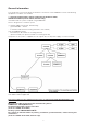
General information This guide refers to the D100 Stage III with direct connection of the SIGMASYS control and indicating equipment or modules to S-module. The Commissioning and Acceptance Checklist for Cerberus D100, A24205-A334-A858 (current edition, German only) should be used for systems coupled using SIGMALINK. D100 is designed as a modular system. It combines SM88 functionality, realized using: – galvanized 8MF...
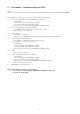
0. Procedure – Commissioning of D100 Note: The Commissioning and Acceptance Checklist will hereinafter be referred to by the abbreviation CAC. The modular concept of the D100 requires the following startup order: 0.1 Check the cable network of the SIGMASYS components – M-module(s) – Control and indicating equipment, type M – Control and indicating equipment, type C See section I.A. of the CAC for SIGMASYS C/M (M-module) 0.
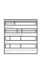
Node line of the S-module Location Operator of the system Name, company Street ZIP code City Commissioning of all modules (S-module, M-module) Date Name Company/ZN, TB Name Company/ZN, TB Acceptance: Date This test record, together with the SMT acceptance test record, is an important part of the abovementioned system. It is one of the documents that must remain with the system or be stored in its immediate vicinity.
Contents Page General information .................................................................................................... 3 0 Procedure – Commissioning of D100 ........................................................................ 4 1 1.1 1.2 1.3 1.4 1.5 Cable network (line resistance) .................................................................................... AMD monitored alarm line ..............................................................................................
Commissioning and Acceptance Checklist D100 A. Commissioning Note This Commissioning and Acceptance Checklist does not contain: – specific elements of loop detector technology AMS, SMU and SSV The tests specified in the checklist for node K01 must also be performed for system configurations with nodes K02 ..., etc. This test record must be completed for each wall or floor cabinet. Any software or hardware faults uncovered during the commissioning and acceptance tests must be reported to SGS in Munich.
Commissioning and Acceptance Checklist D100 A. Commissioning Item no. System part Test Operation/activity Test result/displays I Acceptance test record The acceptance test record consists of the following 4 sheets: Sheet 1 H36-V5068N43 – A. System scope/commissioning I. Cable network To be completed by the site manager Sheet 2 H36-V5069N43 – A. System scope/commissioning II. Control and indicating equipment To be completed by the commissioning personnel – B.
Commissioning and Acceptance Checklist D100 A. Commissioning These commissioning tests shall be performed by the chief engineer. The nodes shall be interconnected in the following order: 1. Node K01 2. Subnode K02 . . . 3. Alarm node level 1 level 2 level 3 The test items contained in the checklist shall be crossed off if the desired result is achieved. Only measuring equipment that undergoes constant checking may be used.
The following must also be ensured: ● The data cable for the log printer (PDR) is only inserted or removed when the 24 V power supply is switched off. ● The node line is reset by pressing the ‘RESET’ button on the MAP module each time fuse 1 on the module (SIB) is switched on. ● The date and time must be checked and if necessary re-entered each time node line K01 is reset (item 7.7. 6).
Commissioning and Acceptance Checklist D100 A. Commissioning Item no. System part Test Operation/activity Test result/displays 1 Cable network Line resistance Measure the line resistances using a Line measuring instrument (Multizet). Check no. the instrument before performing the measurement, e.g. battery voltage, accuracy of measurement. Enter the measured values in the table opposite (use an extra sheet if necessary).
Commissioning and Acceptance Checklist D100 A. Commissioning Item no. System part Test Operation/activity Test result/displays 1.1 AMD monitored alarm line Line resistance Monitored alarm lines with contact detectors MDL fire detector (A24226-A12-A4) The measured actual values for each MPL (see item 1) are beneath the maximum value of 3,000 Ohm.
Commissioning and Acceptance Checklist D100 A. Commissioning Item no. System part Test 1.2 ADW monitored alarm line Line resistance Operation/activity Test result/displays Compl. The measured actual values for each MPL (see item 1) are beneath the maximum value of 1,000 Ohm. 3) As for item 1.1 point 3 ) 4) As for item 1.1 point 4 ) 5) Connect measuring devices to the last detector in the monitored alarm line. Only connect the terminating resistor after the measurement. 1.
Commissioning and Acceptance Checklist D100 A. Commissioning Item no. System part Test 1.4 Trip line for routing equipment Line resistance Operation/activity Test result/displays SEF m Ra + Rb max. 20 Ohm MDL Desired value: Rb + Rc max. 20 Ohm GLU GLS NPF 3) As for item 1.1 point 3 ). Compl. Actual value: Ra + Rb = . . . Ohm Rb + Rc = . . . Ohm 9) Do not connect all poles of the routing equipment even after measurement. Caution! Avoid short circuits and earth faults. 1.
Commissioning and Acceptance Checklist D100 A. Commissioning Item no. System part Test Operation/activity Test result/displays 2 Cable network Line attenuation Measure the line attenuation using a level measuring instrument. Enter the measured values in the table opposite.
Commissioning and Acceptance Checklist D100 A. Commissioning Item no.
Commissioning and Acceptance Checklist D100 A. Commissioning Item no. System part Test Operation/activity Test result/displays 4 Monitored control lines for ÜE and UEW Line termination ÜE and UEW monitored control lines whose trip elements are not terminated must be terminated at the line end (at the unit) with a 1 kΩ / 1 W resistor. ÜE trip lines and monitored control lines are terminated. 5 Power supply Mains supply Visual inspection: Check whether there is a separate circuit.
Commissioning and Acceptance Checklist D100 A. Commissioning Item no. System part Test Operation/activity Test result/displays 6 Control and indicating equipment Preparation: Visual inspection The mains switch on the power supply support is switched off. The mains switches for the power supply modules are in ‘OFF’ position. Monitored alarm lines that are not wired are terminated with appropriate terminating components. 6.
Commissioning and Acceptance Checklist D100 A. Commissioning Item no. 6.3.3 System part Test Operation/activity Test result/displays Switch on the Apply the line voltage – switch on the mains 20 A / 40 A switch on the power supply support SS. power supply Caution! In the case of transformers connected in parallel (40 A), each transformer must be individually checked. The parallel connection (+B, +V, 0 V) must be disconnected to this end. Visual inspection after approx. 3 minutes.
Commissioning and Acceptance Checklist D100 A. Commissioning Item no. System part Test Operation/activity Test result/displays 7 Node line Preparation Never insert or remove a node module while live. Check bridges. 7.1 Node 01 (K01) All interface connections with the exception of the operating panel and log printer must be disconnected. The disconnection is performed at the peripheral devices, not at K01. The interface connections are disconnected. 7.1.
Commissioning and Acceptance Checklist D100 A. Commissioning Item no. System part Test Operation/activity 7.3 SVK Preparation Visual inspection of module type. Measure supply voltage Before plugging in the module, insert the adapter plate in the ‘SVK’ slot. 7.3.1 Test result/displays Connect a voltmeter between point A6 (+) and A2 (–). Voltage is 27 V ± 0.5 V LED ‘24 V vltg.’ (green, SIB) Remove fuse 1 (SIB). Voltage slowly drops to 0 V.
Commissioning and Acceptance Checklist D100 A. Commissioning Item no. System part Test Operation/activity Test result/displays 7.4 SIB, MAP Preparation Visual inspection of module. Soldering jumpers correspond to: (see D100 installation instructions). Visual inspection: Program ID matches the designation and delivery papers. Interface modules must be plugged in. 7.4.1 7.4.2 Battery voltage for clock module Switch on Measure battery voltage between X6 (+) and X7 (–). Vbatt ≥ 3.
Commissioning and Acceptance Checklist D100 A. Commissioning Commissioning a dual MAP Both MAPs are interconnected via serial interface 1 using a head plug. Item no. System part 7. 4.5 Slot 12 Slot 11 Master Slave Test Operation/activity Test result/displays Preparation Visual inspection of module. Soldering jumpers correspond to: (see wall/floor cabinet installation instructions). Visual inspection: Module (hardware) matches the designation and delivery papers.
Commissioning and Acceptance Checklist D100 A. Commissioning Item no. System part Test Operation/activity Test result/displays Generator startup LED ‘Operation’ (green). Generator startup LED ‘Operation’ (green) and LED ‘Bus stop’ (red) lighting up. MAP, dual MAP Slot 12 Slot 11 Master Slave 7. 4.13 Slot 12 Slot 11 7. 4.14 7. 4.15 Slot 12 Idle procedure Generator startup completed. between (Only possible when an operating panel master MAP is connected).
Commissioning and Acceptance Checklist D100 A. Commissioning Item no. System part Test Operation/activity Test result/displays 7.5 ZSB-module (if used) Preparation Remove fuse 6, 7 and 8 on SIB. Press the ‘Bus stop’ button (MAP). LED ‘Bus stop’ (red, MAP) LED ‘Fuse’ (yellow, SIB) Caution! Only one ZSB may be connected per power supply for earth fault monitoring (bridge X24 – X25 inserted). This bridge may not be inserted on the other ZSBmodules.
Commissioning and Acceptance Checklist D100 A. Commissioning Item no. System part 7.5.4 Test Operation/activity Test result/displays Control line: Short circuit Cause control lines 1-4 at the connection board to short circuit. LED ‘Control line 1-4’ (yellow) of the corresponding control line. Remove the short circuit. LED ‘Control line 1-4’ (yellow) Interrupt control lines 1-4 at the connection board. LED ‘Control line 1-4’ (yellow) of the corresponding control line.
Commissioning and Acceptance Checklist D100 A. Commissioning Item no. System part Test Operation/activity Test result/displays 7.7 Standby/ dynamic operating panel Preparation Check the program number. Compare operating mode settings (DIP fix switches for plug-in bridges with …-A5 with SM88 wall/floor cabinet installation instructions. Program number and operating mode setting correspond with designation, delivery papers and circuit diagram. Remove fuse 2 (SIB). Fuse 2 removed. 7.7.
Commissioning and Acceptance Checklist D100 A. Commissioning Item no. 7.7.4 System part Test Operation/activity Test result/displays Authorization switch Using the key, turn the authorization switch to the ‘+’ position and to the ‘–’ position. 7-segment display ‘Operation’ shows: Set level 4 and move the switch to the mid-position. 7.7.5 Interface cable Press the ‘Bus stop’ button on MAP.
Commissioning and Acceptance Checklist D100 A. Commissioning Item no. 7.7.7 System part Test Operation/activity Test result/displays Fuse failure Remove a fuse from the SIB-module, i. e. fuse 4. (fuse 1, the system fuse, and fuse 2, the operating panel fuse, should remain switched on) LED LED ‘Fuse 4’ (yellow, SIB) LED LED ‘Fault’ (yellow, SIB) Press the ‘Acoustic signal off’ button. 7.7.8 Door contact Display line Insert a fuse.
Commissioning and Acceptance Checklist D100 A. Commissioning Item no. System part Test Operation/activity Test result/displays 8 Log printer Printer Visual inspection Printer paper is inserted. Printer FD60 DR2030-9 DL3700 Operation ‘ON’ Start up printer according to instructions (enclosed with the printer). Connect and start up FD60 according to section 9.1 of the D100 installation instructions. Printer paper is inserted. Switch the mains switch on the printer to ‘OFF’ position.
Commissioning and Acceptance Checklist D100 A. Commissioning Item no. System part Test 9 Node ‘K10’… Preparation Operation/activity Test result/displays Tests 9.1 to 9.8 must be performed for each node. Tests completed. The interface connection is switched through. 9.1 Operation ‘ON’ The interface connection to K01 must be started up. 9.2 Restart node Kxx Press the ‘Reset’ button (MAP) of Kxx Display line (operating panel, Kxx): briefly Press the ‘Acoustic signal off’ button.
Commissioning and Acceptance Checklist D100 A. Commissioning Item no. System part 10 Monitored alarm and control lines 10.1 AMD monitored alarm lines Test Operation/activity Test result/displays A WIRE BREAK/SHORT CIRCUIT alarm must be simulated in all monitored lines in the node using the appropriate test detector. Downstream controllers must also be checked. The door contact must be locked to this end.
Commissioning and Acceptance Checklist D100 A. Commissioning Item no. 10.1.3.1 System part Test Operation/activity Test result/displays Reset 1 Reset the alarm at the test detector. Using the control keys, move the cursor ( , underscore) toder the Anzeigenzeile following position in in auf die the display line: Position: and press the ->0<- command input key. Display line briefly shows: and then for approx. 6 s: 10.1.3.2 10.1.
Commissioning and Acceptance Checklist D100 A. Commissioning Item no. System part Test 10.2 AMFK / funct.: Preparation AMF monitored alarm lines Operation/activity Test result/displays Loop in frequency test detector (S24220-D111-A1) at 34APL into the monitored alarm line. Only ever check one detector zone! 10.2.1 Check wire break This test is performed in the same way as the AMD test. The display is analog to that for the AMD test and depends on the supply. 10.2.
Commissioning and Acceptance Checklist D100 A. Commissioning Item no. System part 10.5 Monitored control lines Test Operation/activity Test result/displays Activation of the controllers must be tested at the same time as the monitored alarm lines. Note the supply! Preparation Lock the door contact and keep it closed during the test. Display as for item 7.7.8. Caution! Any third-party automatic fire protection facilities (smoke vents, computer system deactivation mechanisms, etc.
Commissioning and Acceptance Checklist D100 A. Commissioning Item no. System part 11 Detector 11.1 Automatic detector MS7/ 9 11.1.1 Test Operation/activity Test result/displays All detectors must be triggered at their installation location either manually or using an appropriate detector tester. Preparation The detector zone to be tested must first be switched to ‘Revision’ if necessary (see the operating instructions for the procedure).
Commissioning and Acceptance Checklist D100 A. Commissioning Item no. System part Test Operation/activity Test result/displays 11.2 Pushbutton fire alarm call point Visibility/ accessibility Visual inspection during functional check. All detector/switch installation locations are optimally arranged in the operating environment in terms of visibility and accessibility.
Commissioning and Acceptance Checklist D100 A. Commissioning Item no. System part 11.3 Test Operation/activity Test result/displays MDL detector This test is performed as for the pushbutton fire alarm call point (see 11.2). The red LED also lights up on all triggered detectors. Number of detectors inspected: 11.4 Audio Frequency detectors TF2 This test is performed as for the pushbutton fire alarm call point (see 11.2).
Commissioning and Acceptance Checklist D100 A. Commissioning Item no. System part Test Operation/activity Test result/displays 12 Installation order Verification volume Enter the verification volume in the installation order. Verification volume corresponds to actual status.
Siemens AG I BT DE FS SYS www.sbt.siemens.com Issued by Siemens AG I BT DE FS SYS D-81379 Munich © 2001 – 2004 This document contains general description of technical options available, which do not always have to be present. The required features should therefore be specified in each individual case at the time of closing the contract. Order no. A24205-A334-B847 Edition 1 (03/ 04) IA 03040.