
User Manual


23
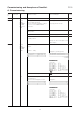
Commissioning and Acceptance Checklist D100
A. Commissioning
Commissioning a dual MAP
Both MAPs are interconnected via serial interface 1 using a head plug.
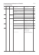
Item System part Test Operation/activity Test result/displays Compl.
no.
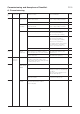
7.4.5 Slot 12 Slot 11
Master Slave
Preparation Visual inspection of module. Soldering jumpers correspond to:
(see wall/floor cabinet installation
instructions).
Visual inspection:
Module (hardware) matches the Module matches delivery note.
designation and delivery papers.
Program ID matches the designation and Program matches delivery note.
delivery papers.
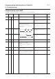
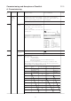
7.4.6 Slot 12 Switch MAP (S24213-A515-A4)
position S5 Master MAP for dual-computer
mode set.
7.4.7 Slot11 Switch MAP (S24213-A515-A4)
position S5 Slave MAPs for dual-computer
mode set.
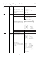
7.4.8 Slot 12 Slot 11 Remove fuse 1 (SIB). System dead.
7.4.9 Slot 12 V-RAM Insert the initialized V-RAM (written with
data) into the master MAP.
Caution: Interface 1 of the 34-fold
connection board of the MAP may not
be wired.
7.4.10 Slot 11 V-RAM Insert the
uninitialized (empty) V-RAM
into the slave MAP.
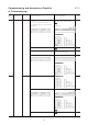
7.4.11 Slot 12 Slot11 Connect the Plug in the modules and establish the Master MAP and slave MAP
interface interface connection between the master connected.
MAP and the slave MAP via a 10-pin flat
cable (enclosed with the node line).
7.4.12 Slot 12 Slot 11 Switch on Insert fuse 1 (SIB). The system is live.