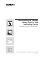
Multifunctional Danger Alarm Control and Indicating Panels SIGMASYS C and M (M-Modules) Commissioning and acceptance checklist Edition April 2002
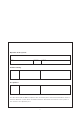
Operator of the system: Name, company Street Postal code Town/city Commissioning: Date Name Company/ZN, TB Name Company/ZN, TB Acceptance: Date This document and the SMT acceptance test record are part of the aforementioned fire alarm or intrusion detection system. Both should be treated as documents that remain in the system or are stored in close proximity to it.
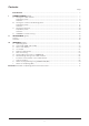
Contents Page Introduction........................................................................................................................ 5 I COMMISSIONING (white).................................................................................................... A Testing the cable network .............................................................................................. Preparatory work.................................................................................................
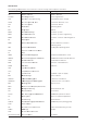
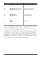
Introduction The following abbreviations are used in this commissioning and acceptance checklist: Abbreviation Term Meaning AE Addresselement Address Element ALORG Alarmorganisation Alarm Organization ALZ Alarmzwischenspeicherung Intermediate alarm storage APC8 Anschlussplatte C, 8 PL Connection board C, 8 PL APL Anschlussplatte Connection board BF Bedienfeld Operating panel BG Baugruppe Module BMA Brandmeldeanlage Fire alarm system BMT Brandmeldetechnik Fire alarm systems engin
Abbreviation Term Meaning SEK Sensorkomminikationsmodul Sensor communication module Si Sicherung Fuse SIPL SIGMASYS-Primärleitung SIGMASYS monitored line SIPL-L SIGMASYS-Primärleitung als Loop SIGMASYS monitored loop line SIPL-S SIGMASYS-Primärleitung als Stich SIGMASYS monitored spur line SMC-GRPL SIGMASYS-C Grundplatte SIGMASYS C base plate SOC System Organization Controller SOP SIGMASYS Operating Panel (BF) SPL Steuerprimärleitung Monitored control line SSL Steuersekundärleit
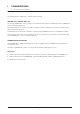
I COMMISSIONING A Testing the cable network Test equipment and tools The following tools and devices simplify commissioning: IBS2000 tester (S24218-F257-A1) For testing SIGMALOOP lines and spur lines and their loop elements independent of the SIGMASYS control and indicating panel. The prompt detection of faults can lead to significant quality improvements and cost reductions by decreasing the work effort. The IBS2000 tester must be used when commissioning SIGMASYS spurs at a SIGMLOOP splitter.
I COMMISSIONING A Testing the cable network BMT Preparatory work a The cable network is fully laid and wired through to the control and indicating panel. The cable shields are through-connected in detector bases, elements and distributors, and grounded in the control and indicating panel: at one end in the case of spur lines and at both ends in the case of ring cables. b SIGMASYS monitored lines (SIPLs): All detector bases and elements are connected; automatic detectors are not yet plugged in.
I COMMISSIONING A Testing the cable network Pos. no. System part Test Operation / task Test result /displays Comp. 1 Cable network Line resistance SIGMASYS monitored lines (SIPL): Each SIPL can be tested in advance using the base tester in accordance with Pos. III.G. Otherwise, the test can be deferred until commissioning of the control and indicating panel. Lines whose resistances may be close to the permitted upper limits should be measured in advance.
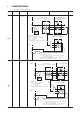
I COMMISSIONING A Testing the cable network Pos. no. System part Test Operation/task 2 SIPL-L Line resistance SIGMASYS monitored loop lines (SIPL-Ls): BMZ Test result/displays e. g. SIGMAEXPERT detector base with PLUS clamp block e. g. Element 4STE / transponder, HFM, etc. S S S a a a a S + a + a b b b b Comp. b b 1) e. g. SIGMAEXPERT base tester with STANDARD clamp block Ohmmeter Permitted line resistance: a + b= < 200 Ω – n x 0.
I COMMISSIONING A Testing the cable network Pos. no. System part Test Operation/task Test result/displays 3 SIPL-S Line resistance SIGMASYS monitored spur lines (SIPL-Ss): e. g. element In BMT: e. g. SIGMAEXPERT In BMT: 4STE / transponder, HFM, etc. base tester with PLUS clamp In IMT: Transponder SP I3510, SPI 3400 block In IMT: e. g. SDI1230 BM GMZ S a b S S a a a S + a + b b b BMT/ IMT Comp. a b b 1) Ohmmeter Permitted line resistance In BMT: – a + b: < 200 Ω – n x 0.
I COMMISSIONING A Testing the cable network Pos. no. System part Test Operation/task Test result/displays Comp. 4 MPL for fixed threshold detector (MS6, MS7, MS9) in SIG. C/M Line resistance a. Hand-held fire detectors and detector bases for automatic detectors are connected. b. An end-of-line resistor (RE) is used in the last detector/detector base of each MPL. c. Measure line resistances and check whether they are permitted. GMG with automatic detectors: GMG-S (in SIG M) or 4STE (in SIG.
I COMMISSIONING A Testing the cable network Pos. no. System part Test Operation/task Test result/displays 4 Monitored line for alarm device Line resistance Optical alarm device, acoustic on SPI 3510 Comp. 1) Ohm 1) Short-out end-of-line resistor in alarm device. IMT Device Visual test Alarm device Cur.value Permitted max. Ohm value Ohm Alarm sirens 10 Flashing lights 10 Combined Flashing lights 10 alarm lights/sirens Alarm sirens 10 Remove measurement structure.
I COMMISSIONING A Testing the cable network Pos. no. System part Test Operation/task Test result/displays 5 Control lines Line resistance Line resistance should only be measured for control lines for which a permitted maximum value has been specified in the implementation plan of the control and indicating panel. Procedure: 1) Short-out SPL of the ÜE or ÖA in the control and indicating panel as shown in Pos. 5.1.1. 2) Carry out the line measurement.
I COMMISSIONING A Testing the cable network Pos. no. System part Test Operation/task 5.2 SSL via relay (option) Line resistance Line resistances should only be measured for control circuits for which a permitted maximum value has been specified in the implementation plan of the control and indicating panel, which are switched by a make contact, and whose control organs have been supplied by the power supply of the BMA.
I COMMISSIONING A Testing the cable network Pos. no. System part Test Operation/task Test result/displays 7 Release line to routing equipment (ÜE/ÜG) Line resistance (is preset by the routing equipment [ÜE/ÜG]). Reading complies with the specifications of the routing equipment. Reading: Mains supply to the control and indicating panel Visual inspection: Check whether separate power circuit exists. Power circuit fuse-protected separately.
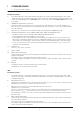
I COMMISSIONING B Testing the control and indicating panel Preparatory work The following tasks must be carried out before testing the control and indicating panel: a: Cable network: Immediately before the control and indicating panel test, all detector bases must be equipped with the detectors provided, as entered in the installation plan/detector zone list. We recommend testing the individual SIGMALOOP/spurs with the IBS2000 tester.
I COMMISSIONING B Testing the control and indicating panel Pos. no.
I COMMISSIONING B Testing the control and indicating panel Pos. no. System part 1.2 General Mains power supply feeding BMT/ IMT Test Protectivmeasures (FPE) 1.2.1 SIGMASYS C Switch on PSU insert BMT/ IMT Measure operating voltage Operation/task Test result/displays Visual inspection Mains feeding wired in accordance with VdE, fuse uniquely identified. Check whether FPE is connected and meets VdE requirements.
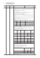
I COMMISSIONING B Testing the control and indicating panel Pos. no. System part Test 1.2.2 SIGMASYS M Switch on PSU insert Measure operating voltages at node line X10 BMT/ IMT Test result/displays Insert mains fuse “F1”. Visual inspection. PSU: LED “Mains” on. DC converter: LED “Oper.” on. PSU insert and converter must not show any reaction. Name –25 V Term. 1 –15 V 2 –15 V 3 –00 V –05 V 4 5 –UB +UB 7 8 Comp. Reading –27 V +/– 0.4 V (to 0 V) –15 V +/– 0.2 V (to 0 V) –15 V +/– 0.
I COMMISSIONING B Testing the control and indicating panel Pos. no. System part Test Operation/task Test result/displays 1.3 Softwareprogramming Preparatory work “Reduced operation” must be activated before transmitting data from SIGMAPLAN: Switch control and indicating panels to operating level 4 (see Pos. 1.4). Operating display shows operating level 4.
I COMMISSIONING B Testing the control and indicating panel Pos. no. System part Test 1.4 SOP (operating b. BMT: panel) Display Operation/task Comp.
I COMMISSIONING B Testing the control and indicating panel Pos. no. System part Test Operation/task Test result/displays 1.5 General tests Mains failure In all PSU: Remove fuse “F1” PSU: LED “Mains” off OP: Surface LED “Fault” flashing General ind. “Fault” on Buzzer on Fault “Power supply” on Display: FAULT . . . . . . . . BMT/ IMT Insert fuse F1 Battery failure Displays go out In PSU: Remove fuse “F2” PSU: LED “Battery fault” off OP: Surface LED “Fault” flashing General ind.
I COMMISSIONING B Testing the control and indicating panel Pos. no. System part Test 1.6 Entry of date and time: BMT/ IMT Operation/task Test result/displays Key: 2 x COMMAND << / >> until Confirm Confirm << / >> until Confirm Enter: “0 … 9” Confirm Enter: “0 … 9” Confirm Display: COMMAND COMMAND COMMAND Comp. MG ?? IND.PAN. IND.PAN. ?? COMMAND TIME ON TIME: 00:00:00 TIME:: hh:mm:ss … DATE: … DATE: POSITIVE TIME ON IND.PAN. 00:00:00 DD:MM:YY IND.PAN.
I COMMISSIONING B Testing the control and indicating panel Pos. no. System part 2 MPL and SPL Test SIPL-L Test result/displays Comp. A wire break and short-circuit must be simulated on all monitored lines in the control and indicating panel. Raising of the alarm by all connected detectors and elements must also be tested. The door contact must be locked for the tests. Releasing of unwanted control facilities must be prevented using suitable measures. IMT 2.
I COMMISSIONING B Testing the control and indicating panel Pos. no. System part Test Operation/task Test result/displays 2.3 MPL for fixed threshold for pulse-polling detector (MS6, MS7, MS8, MS9) Fault On all MPLs: Wire break or short circuit “on”. OP: BMT Surface LED “Fault” flashing General indication “Fault” on Buzzer on Scroll on Display and lists: Faulty MPLs (and elements) Further operation/displays correspond to the system operating panel overview.
I COMMISSIONING B Testing the control and indicating panel Pos. no. System part 2.6 Control and indicating panel SPL ÜE Test Fault Operation/task Test result/displays Before testing, the readings must be loaded by pressing the key S4 in SMC and S5 in SAC for approximately 3 seconds. During loading, the operating LED flashes on the SAC module. If the reading is outside the range 100-1000 Ohm or 2k2, the operating LED flashes on the SAC and the corresponding fault message is displayed.
I COMMISSIONING B Testing the control and indicating panel Pos. no. System part 2.7 Commissioning Double MPC 2.8 Test Operation/task Test result/displays Initial start-up: The system has no power. Connect all modules (SOC and MPC). Check the connections of the U-APL using the cables supplied with the MPC modules and the APL20 (see installation instructions).
I COMMISSIONING C Terminal testing Preparatory work The detector zones to be tested must be switched to “Inspection” before the detector/terminal test. Key: Display Indicating panel COMMAND 2 x COMMAND MG Confirm COMMAND MG _ Enter number COMMAND MG 1234 Confirm 2 x SIGMA ... XXX With key >> until SIGMA ... INSP.ON MG 1234 Confirm POSITIVE INSP.ON MG 1234 ...
I COMMISSIONING C Terminal testing Pos. no. System part Test Operation/task Test result/displays 1 Auto. detector Equipment Zone-wise connection of the correct detector inserts, setting of the required sensitivities or visual inspection if necessary. The detector type and sensitivity, e. g. switch settings, correspond to the installation plan or detector zone list at all detector installation locations.
I COMMISSIONING C Terminal testing Pos. no. System part Test Operation/task Test result/displays 2 BMT/ IMT Implementation documents Current status Visual inspection, correct implementation documents if necessary. The implementation documents correspond to the current status of the system. See the acceptance test record for completeness. 3 Handheld fire detectors Visibility accessibility Visual inspection during function test.
I COMMISSIONING C Terminal testing Pos. no. System part Test Operation/task Test result/displays 4 Distributor Designation and identification Visual inspection. Make an impression on the lead seal to permanently change its shape. Count VB no. when the distributor blocks 12 and 9U are plugged in. Impression made on lead seal for permanent shape change. Add. elements in SIPL Visibility, accessibility Visual inspection during function test.
I COMMISSIONING D SIGMANET commissioning WARNING! Stand-alone power supplies cannot be converted to a SIGMANET. Basic information: Avoid signal avalanches during commissioning! Example: Signals for faults in loop elements (detectors, transponders, inputs / outputs) and devices (printers, FBFs, etc.). Wherever possible, only program peripherals that are also connected during commissioning. 1. Preferred option b. c. d. e. f. g. h. a.
I COMMISSIONING D SIGMANET commissioning NET configuration (Version 2.6 or later) The NET configuration feature can be used to change the configuration of a unit in a SIGMANET system while the system is running (with the exception of SIGMALINK). Data can be loaded from any NET unit (control and indicating panel, NET operating panel, INFOPANEL). The unit to be reprogrammed must be switched to reduced operation in advance by means of a command.
I COMMISSIONING D SIGMANET commissioning NET configuration (Version 3.1 or later) SIGMASYS Version 3.1 or later features two different procedures for configuring fault evaluation. Setting SIGMANET Options Procedure Assignment Connection delay Modem data Conn. no.: none Behavior in SW Version 3.0 or earlier (no default modems) Fault handling 100 sec (in accordance with EN 54-2) Behavior in SW Version 3.1 or later 10 sec (in accordance with VdS IMT 2252) Help Cancel The 100 sec.
I COMMISSIONING E 1 Transliner ring bus Differences Between SIGMALOOP and TR Technology TR does not have any loading phases. The b wire (data line) is also used to supply the peripherals with 30V power. The data for communication between the control and operating panel and the detectors is transferred via an additional 1.6 V voltage level difference. The a wire serves as reference potential (0V). The optical line tester which provides a visual representation of line states can no longer be used here.
I COMMISSIONING E Transliner ring bus 3 Notes on Operating the Control and Indicating Panel 3.1 Restoring, Deactivating or Activating the LOOP A loop malfunction can be resolved with the command RESTORE LOOP. A hardware reset must be performed on the appropriate LPC if element configuration was modified on the network, because the commands DEACTIVATE LOOP and ACTIVATE LOOP do not reset the loop in a TR. The control and indicating panel only tries to reset the last configuration measured. 3.
II ACCEPTANCE Preface The acceptance test must be carried out by an employee authorised to accept. The test positions listed in the acceptance checklist must be carried out in accordance with the system configuration (implementation documents) and programming (system pass). Acceptance can only take place following successful completion of the commissioning test. If defective terminals or modules are discovered during the acceptance test, they must be replaced.
II ACCEPTANCE Pos. no. System part Test 1 Power supply Measure operating voltage BMT/ IMT Operation / task SIGMASYS C: 24 V: Terminal 4 00 V: Terminal 1 in PSU Test result / displays Comp. Node line connector X10 Target value (temperature-dependent): SIGMASYS M: C: 27 … 29 V M: 26,3 … 29 V +UB: Terminal 8 –UB: Terminal 7 Current value . . . . . . . . V If the current value is outside the target value range, the battery is probably still charging.
II Pos. no. ACCEPTANCE Test Operation / task Test result / displays 1 (ctd) Battery failure Remove battery fuse from PSU and the re-insert it. PSU LED “Battery fault“ after 1 min. on Other displays as for bias current in power failure (see above) BMT/ IMT Battery sticker Check/identify the year in which the battery is to be changed. Sticker order no.: A24205-A331-A538-*-04 Year of replacement identified. Fuse failure in module Simulate fuse failure in accordance with Pos. I B 1.
II Pos. no. 3.2 ACCEPTANCE System part Test Operation / task Test result / displays MG with direct alarm and MG with alarm delay Alarm “MAN.TRIP” (Pos. 3.1) Display: OP: – always: ALARM . . . . . . . . . Surface LED flashes red General ind. “Alarm” on Buzzer on – Programming-dependent: General ind. “Meldung” on “ÜE tripped” on “SD unlocked” on “Control facility rel.” on “ÖA released” on BMT 3.3 MG with ALORG BMT 3.3.
II Pos. no. ACCEPTANCE System part Test Operation / task Test result / displays 3.4 BMT MG with coincidence changeovers (AHK) 3.4.1 MG in 2MGAHK (SIGMAPLAN programming: “Control emergencies on initial event” activated) Displays 2MGAHK with First alarm as advance warning First alarm as alarm Both MGs connected or OK Alarm first MG Release alarm at detector (Pos. 3.1) Display: PREWARNING . . . . . . . . OP: Surface LED flashes red General ind.
II Pos. no. 3.4.2 ACCEPTANCE System part Test Operation / task Test result / displays MG2 in 2MG alarm AHK (SIGMAPLAN programming “Control emergencies on initial event” not activated). Displays 2MG alarm AHK with First alarm as First alarm as advance warning alarm Both MGs connected or OK Alarm first MG Release alarm at detector (Pos. 3.1) Display:PREWARNING . . . . . . . . OP: Surface LED flashes red General ind. “Alarm” on Buzzer on Alarm second MG (changes) Release alarm at detector (Pos. 3.
II Pos. no. 3.4.3 ACCEPTANCE System part Test Operation / task Test result / displays MG with 2MAHK *) Displays 2MAHK with First alarm as advance warning First alarm as alarm All elements connected or OK BMT Reslease alarm at one detector in MG (Pos. 3.1) Display: PREWARNING . . . . . . . . OP: Surface LED flashes red General ind. “Alarm” on Buzzer on Release alarm at second detector in MG (changes) Display: ALARM . . . . . . . . OP: Programming-dependent: General ind.
II Pos. no. ACCEPTANCE System part Test Operation / task 3.5 BMT MG with event delay 3.5.1 BMT Release at OP Test result / displays Alarm “MAN.TRIP.” (Pos. 3.1) Reset 3.5.2 Release at detector Display same as direct alarm (Pos. 3.2) Same as direct alarm (Pos. 3.2) Release detector with detector tester Alarm criterion is above the delay time (programmable from 0 to 2 minutes 30 seconds) without interruption.
II Pos. no. ACCEPTANCE System part Test Operation / task 3.8 BMT MG for “Technical signals” MG for “Fault signals” 3.8.1 Release at OP Test result / displays Alarm “MAN.TRIP.” (Pos. 3.1) Display: OP: Programming-dependent Surface LED “Fault” on General ind. “Fault” or “Signal” on Buzzer on The signal type can be found in the list or Reset 3.8.2 BMT Release via MPL Same as direct alarm (Pos. 3.2) *) Display and request of signal type as for Pos. 3.8.1.
II ACCEPTANCE Pos. no. System part 4 BMT/ IMT Alarmforwarding 4.1 Test Operation / task Test result / displays Check or enter type FBF The displays and functions of the FBF were tested during the acceptance test. BMT The locking insert (profile semi-cylinder in accordance with DIN 18252) which was procured in collaboration with the regional fire brigade, is integrated into the FBF. The FBF key was given to . . . . . . . . . . . . . . . . . . . . . . . . . . . . . 4.
II ACCEPTANCE Pos. no. System part Test Operation / task 6 SMT- The SMT acceptance test log consists of the following four sheets: acceptance test log Sheet 1 –A Test result / displays System configuration/commissioning I Cable network LZF order no.: BMT/ IMT Sheet 2 H36-V5068-N43 –A System configuration/commissioning II Control and indicating panels Fill in, sign: Commissioner –B Acceptance Fill in, sign: Employee authorised to accept LZF order no.
III APPENDIX A Operating levels As the SIGMASYS C and M danger alarm control and indicating panels are generally operated by various employee groups, operating authorization has been subdivided into four operating levels. The operating levels are set at the operating panel. Operating level 0: Indicating panel operating panel (info panel) This operating panel always displays the operating level 0.
III APPENDIX A Operating levels Operating level 3: For authorised persons and maintenance personnel (Includes commands in lower operating levels) – System test, commissioning – Enable/disable monitored alarm line – Initialise monitored alarm line – Information on monitored alarm line – Output address physically – Release test alarm – Output version – Reset key depot – Reset tamper and hold-up – Reset SD tamper signals Operating level 4: Planner (Includes commands in lower operating levels) – Programming/
III APPENDIX B Commands (BMT and/or IMT) The order in which command recipients are displayed on the screen is dependent on the programming. The specified operating level is the lowest one required to enter the relevant command. Higher operating levels also have automatic access to lower ones. Command recipients Commands Op. level Comments MG DEACTIV. ACTIVATE RESET REC.STRT ABOR.REC. INSP.ON INSP.OFF INSP.DEL SENS.HI SENS.LO MAN.TRIP INDIV. ?EO AL ?EO ?CH.CSTDY AL OFF AL CANC.
III APPENDIX B Commands Command recipients Commands Op. level Comments OBJECT AT OFF AL OFF ?ZO ARMED ?ZODISARMED ?ZONE AL RESET AL ACT EV OFF CO.OFF AT ON AL ON EV ON CO ON RESET AT RESET CTRL RES. EV. ACT CTRL ACT LOC. OFF LOC. ON ALORG.OFF ALORG.ON ABOR. REC. DAY ON NIGHT ON NIGHT TIME TIME 2 2 2 2 1 2 2 2 2 2 2 2 2 2 2 2 2 2 2 2 1 2 2 2 2 INSP.DEL. ?AREA ?RESP. 2 1 1 ?E1-E2 2 ?E2-E1 2 ?CH.CSTY ALARM OFF REC.STRT. WALK. OFF WALK. ON ARM DISARM DEACTIV.
III APPENDIX B Commands Command recipients Commands ROUTING EQUIPMENT Op. level Comments EV ON RESET EV. RESET EV. ACT OFF ON ABOR. REC. INSP.ON INSP.OFF INSP.DEL SENS.LO SENS.HI ?DET. AL. ?DET. OFF ?DET. INSP. ?DET. ZONE 2 2 2 2 2 2 1 2 2 2 2 2 1 1 1 1 Enable evacuation for zone of exposure Reset Reset evacuation alarm for zone of exp. Activate evacuation alarm for zone of exp.
III APPENDIX B Commands Command recipients Commands CONTROL FACILITY Op. level Comments PT. ACT PT. ON PT. OFF DEACTIV. ACTIVATE RESET CONTROL PHYS.DIS. 2 2 2 2 2 2 2 3 Control in reachable part of OBJ Enable in reachable part of OBJ Disable in reachable part of OBJ Disable evacuation alarm Enable evacuation alarm Reset evacuation alarm Activate evacuation alarm Output displayed number physically DEACTIV. ACTIVATE RESET CONTROL PHYS.DIS.
III APPENDIX B Commands Command recipients Commands Op. level Comments PLAN. OP PHYS.DIS. 3 Output displayed number physically B. LEVEL 1 Entry of operating level BER.CODE 1 Change authorization code ?RESP 1 Information on responsibility list ACCEPT 2 Take over responsibility without dialog B. LEVEL 1 Entry of operating level BER.CODE 1 Change authorization code AUD.
III APPENDIX B Commands Command recipients Commands Op. level Comments SDN RESET-IT 4 Privileged resetting RESET 2 Reset ?CH.CSTDY 4 Test locking standby DEACTIV. 2 Disable ACTIVATE 2 Enable RESET 2 Reset printer PHYS.DIS. 3 Output displayed number physically LOG BOOK 1 Print operating log END LOUT. 1 End of list output PT.
III APPENDIX C Terms and displays The SIGMASYS operating panel (OP) and SIGMASYS printer log (Dr) are organised into different areas, in which certain texts are displayed/printed out. Text 1 Text 2 Text 3 Display OP/Dr: Text 4 (list texts, printer) Dr: Error and note texts, and list texts OP: Below is an alphabetical list of possible texts, together with their meanings. Term/Display Meaning Text 1 1. ALARM 0 1 2 3 4 ACTIVE ALARM ALERT COMMAND BMT.COM. ELEMENT ERR 001-022 ERROR 01-03 INSP.AL. INSP.
III APPENDIX C Term/Display Terms and displays Meaning Term/Display Text 2 – Commands (continued) ?E0 AL. ?E1-E2 ?E2-E1 ?CH.CSTDY ?DET.ZONE ?DET.OFF ?DET.AL ?DET.INSP. ?MPL ?RESP DEACTIV. AL OFF AL RESET AL ACT AL ON ALORG.OFF ALORG.ON PERMITT LOG BOOK ERA. EDIT.CODE INDIV. UNLOCK ABOR.REC REC.STRT INSP.OFF INSP.ON INSP.DEL. ENDLOUT. MAN.TRIP. MPL INIT. NIGHT ON CAN NIGHT NIGHT TIME ACCEPT LOC.OFF LOC.ON PHYS.DIS. EV.DEACTIV. EV.OFF EV.ON EV.RESET EV.ACT EV.ON REDUC.OP RESET CO. OFF CTRL RES.
III APPENDIX D List output If a printer is connected to the control and indicating panel, printouts of current lists can be initiated as follows: Quantity Key 2 x COMMAND << / >> until Confirm No. printer “n” Confirm << / >> until Confirm n. LC t.. Display COMMAND COMMAND COMMAND COMMAND COMMAND COMMAND POSITIVE Display MG PRINTER PRINTER PRINTER PRINTER PRINTER t.. PL.LIST PL.LIST ?? ?? n. n./ n./LC n.
III APPENDIX E 1 Detector replacement Detector replacement in SIGMASYS monitored alarm lines (SIPLs) In SIGMASYS 2.3 or later, it is possible to request a self-initiating fault in optical smoke detectors in the form of a maintenance request using SIGMADIAG. This provides the service engineer with an effective tool for increasing detector availability. A maintenance request means that the reading of a detector approaches the fault range.
III APPENDIX E 1.7 Detector replacement Reactivate MGs of the SIPL individually: Procedure as for Pos. 1.3, except for: 1.8 Key Display << / >> until Confirm ... ... ... with INSP.OFF COMMAND POSITIVE ... ... ... of last MG Display INSP.OFF INSP.OFF MG nn MG nn Inspection off Delete inspection SIGNALS from lists: Procedure as for Pos. 1.3, except for: << / >> until Confirm ... ... ... with INSP.DEL COMMAND POSITIVE ... ... ... of last MG INSP.DEL INSP.
III APPENDIX F SIPL line testing Several simple testing options are outlined below. 1. Line testing by measuring the a-wire: The a-wire in the SIPL is wired through in all bases/elements. The correct a-wire wiring and its resistance can be measured from the control and indicating panel using an ohmmeter. – In the SIGMA loop, the overall resistance of the a-wire must not exceed 50 Ohm. – In the SIGMA spur, the overall resistance of the a-wire must be under 100 Ohm.
III APPENDIX G OLPSI (optical line tester in SIGMASYS) If a SIGMASYS loop or spur line with connected detectors and elements is connected to the control and indicating panel and switched on, initialization takes place within the first few minutes. Following this, the usual data exchange between the control and indicating panel and elements takes place on the line. Initialization is repeated after a line fault.
III APPENDIX H Shield through-wiring in the cable network The cable shield (drain wire) must be through-connected in all elements/detectors. This considerably reduces the fault-influencing capabilities of the control and indicating panel and the SIPL. If faults due to a possible open cable shield are suspected, we suggest the following measurement: 1. The cable to be measured must be separated from the system in a secure way and the a-wire connected to the shield. 2.
III APPENDIX I Insulation measurement in the cable network The insulation resistance of the individual line to earth must be at least 500 kOhm. According to DIN 14675, Pos. 5, Acceptance, the insulation resistance of each individual line must be measured. The following should be noted: 1. The line to be measured must be separated securely from the system and the a/b-wires short-circuited. Insulation measurements between the a-wire and b-wire wire are not permitted. This could damage detectors/elements.
III APPENDIX J 1 Loop restoration After resolution of an error without changes to the SIGMALOOP, the fault is corrected by loop restoration. This command has no influence on the assignment of elements and control facilities to the loop. 1.2 SIPL restoration Key Display 2 x COMMAND << / >> until Confirm e. g.: 0103 L/S Confirm << / >> until Confirm COMMAND COMMAND COMMAND COMMAND COMMAND COMMAND POSITIVE Display ?? MPL REST. MPL REST.
III APPENDIX K Notes on programming using SIGMAPLAN (IMT) Programming examples: The detector type on the transponder SPI 3400 (with the exception of a glass-breakage detector) only influences text 3 of the display in the control and indicating panel.
III APPENDIX K Notes on programming using SIGMAPLAN (IMT) Example of the IR detector – Variant A (one detector) (SGB10) LOOP/Spur Coupler Connection Connection Connection Connection SPI 3400 – Small transponder 1 detector type glass-breakage detector 2 free 3 free 4 actuator type reset output 1 4 Reset output, inverse Activation list for corresponding zone Evaluation of the monitored line is only interrupted during resetting when programming the detector type “glass-breakage detector”.
III APPENDIX K Notes on programming using SIGMAPLAN (IMT) If hold-up detector zones are to be alarmed “quietly”, activation must occur without the hold-up detector zones of the zone. Actuators in general: Actuators on transponder SPI 3400: All monitored except for VdS signal emitter and faults. Actuators on indicating panel module SPF 3200: All except VdS signal emitter monitored, faults and dynamic outputs (including reset output). Switching facilities: SIGMALOCK only on transponder SPI 3510.
III APPENDIX K Notes on programming using SIGMAPLAN (IMT) The tamper signal is “frozen” by the control and indicating panel in the armed status. Resetting can only be carried out by the maintenance service, when the error has been resolved and the resistance value of the switching facility is 1 kΩ. The tamper is now reset using “Reset” at operating level higher than 2. In the SIGMASYS C and M control and indicating panels with versions higher than 2.
III APPENDIX L Notes on tampering (IMT) Virtual signals from control and indicating panel faults Type Designation Text 1 Text 2 “Non-coded text” Text 3 Org. add. or EO no. 1 GR Tampering with key depot Alarm – SD ‘_<ÜE no.
Enclosure Overview of operating panel and nomenclature Number Display / operating element Light display for – routing equipment (BMT) – key depot (BMT) – control facility (BMT) – local alarm (IMT) – control facility – Alerting 1 (IMT) – Alerting 2 (IMT) Key depot activated / tampered with Control facility released / tampered with / disabled External signal emitter released/tampered with Key for Information: Call the function “Information lists” (see section 8.1).
Number Display / operating element Meaning / operation Fault Light display “System” Status display System faulty (nothing on display) Status display Power supply faulty (mains, battery, fuse). Light display “System programming” “Alarm” “Fault” “Disablement“ “Signal” “Inspection” GENERAL DISPLAY: A lighting display indicates existing entries in the assigned lists. Query via Information. Light display “Call” Light in the event of an alarm, if routing equipment is faulty or deactivated.
76a
Notes 76
Siemens AG Issued by Siemens AG I BT DE FS SYS D-81379 Munich © 1999 – 2002 Ref. No. A24205-A337-B987 Edition 8 (04/ 02) IA 04020.1 Delivery subject to availability; right of technical modifications reserved. EK 4500054435 TL/G Printed in the Federal Republic of Germany on environment-friendly chlorine-free paper.