General fire detection system planning Planning guidelines Fire & Security Products Siemens Building Technologies Group
Data and design subject to change without notice. / Supply subject to availability. E Copyright by Siemens Building Technologies AG Wir behalten uns alle Rechte an diesem Dokument und an dem in ihm dargestellten Gegenstand vor. Der Empfänger anerkennt diese Rechte und wird dieses Dokument nicht ohne unsere vorgängige schriftliche Ermächtigung ganz oder teilweise Dritten zugänglich machen oder ausserhalb des Zweckes verwenden, zu dem es ihm übergeben worden ist.
Foreword . . . . . . . . . . . . . . . . . . . . . . . . . . . . . . . . . . . . . . . . . . . . . . . . . . . . . . . . . . . . . . . 1 1 Compliance with local national guidelines and regulations . . . . . . . . . . . 1 2 Extent of monitoring . . . . . . . . . . . . . . . . . . . . . . . . . . . . . . . . . . . . . . . . . . . . . . . 2 3 Zones with fixed extinguishing systems . . . . . . . . . . . . . . . . . . . . . . . . . . . . 4 4 4.1 4.2 4.3 4.4 4.5 Choice of detector . . . . . . . . . .
II Fire & Security Products Siemens Building Technologies Group 06.
Foreword These planning guidelines contain the basic know-how for the planning of sophisticated fire detection systems. It is an important tool and reference work for the planner of fire detection systems. It contains basic information which applies to all fire detectors. As far as possible we have tried to provide a layout which can be used irrespective of detector type. Specific detector data is provided where it is needed in depth.
2 Extent of monitoring In principle we should endeavour to provide complete monitoring in all fire compartments. The monitoring of selected fire compartments (partial monitoring) or selected rooms or groups of rooms (selective monitoring) should only be applied exceptionally.
Void features Inaccessible or accessible and without fire load or sources of ignition or few and fire-proof electrical installations (at least self-extinguishing) Means of monitoring in this sub-section none Accessible with electrical installations with cable trays concentrated at certain places or built-in electrical equipment (e.g.
3 Zones with fixed extinguishing systems Fixed extinguishing systems should be installed in zones: Where rapid fire development and spread is highly likely (solvents stores, plastics stores etc.) Where the building construction has inadequate fire resistance (e.g. danger of collapse due to unprotected steel construction) With a high concentration of valuable property, or in which heavy damage can be expected calling for additional fire risk reduction (EDP systems, switchgear etc.
4 Choice of detector 4.1 General The specifying of which detector to use and where depends on the monitoring category or the general monitoring aim of the FDS* room height the ambient influences including deceptive phenomena 4.1.1 Monitoring categories / monitoring aims of the FDS The monitoring categories cover three different general monitoring aims of the * fire detection system. They are adjusted to the fire risk and other application criteria.
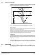
4.1.2 Influence of room height The higher the room, the weaker the influence of the fire phenomena to be detected. With increasing room height, in view of the greater room volume, an incipient fire can be larger without increasing the danger of rapid fire spread or a flashover. Heat (convection) Room height Rauch h 3 Radiation h 2 h 1 Seat of the fire Fig.
Monitoring category I II III Monitoring g tar tar- Suitabilityy rating g get of the DFS U = Suitability on the basis of monitoring target or monitoring category H = Suitability on the basis of room height h U x H = Detector suitability Rating: U x H = 4 very good suitable 2 well suited 1 suitable 0 in i certain t i cases Detection /must be checked of: - unsuitable open fire open fire smouldering fire (desired) open fire Suitability value of types of detector Smoke detectors F-detectors Sensitivity R-d
4.1.4 Combining different detectors Fire phenomena vary in their physical characteristics according to the combustible involved and fire development so that frequently fire detectors with different operating principles have to be used.
4.1.
Note: The detection characteristics of the new AlgoRex generation of detectors with AlgoLogic, differentiate themselves in some ways considerably from the types of detector dealt with below. This mainly concerns the response behaviour of the F- and R-types as well as the recommendations on the suppression of false alarms. AlgoRex detectors are described in the DS11 manual.
Detector setting in dependence of monitoring category, room criteria and room height Application features Monitoring g category g y Fig. 6 Sensitivity setting (1-3) / Smoke entry Room height in metres Room criteria <3 3...6 6...12 12...
4.2.2 Smoke detector R-Type Application: Where pyrolytic smouldering fires are to bee expected Is only limited suitable for dusty environments such as textile factories, carpenters’ shops, mills etc. If too many dust particles or individual fibres enter the detector’s highly sensitive optical system, this can lead to false alarm.
Detector setting in dependence of monitoring category, room criteria and room height Application features Monitoring g category g y Fig. 7 Sensitivity setting (1-3) / Smoke entry Room height in metres Room criteria <3 3...6 6...12 12...
4.2.3 Linear smoke detector A2400 Application: In particular it is used in large rooms in which smoke can be expected as fire phenomena and wherever it is not excluded by ambient conditions The linear smoke detector is often superior to point-type detectors, e.g.
permissible ambient tem− perature in °C -10 °...+60° Humidity max. applica− tion height above sea level (m) IEC protec− tion cat. cat (de− tector / base) ≤75°C unlimited IP 52 Degrees of resistance to dry dust Fibres (heavy fibre content) Accumulation of moist, dirt, grease very good good adequate Influence of air currents transient max. continuous max. no influence periodic external cleaning 15 Fire & Security Products Siemens Building Technologies Group e432d 06.
4.3 Heat detectors types D/T Application: In an incipient fire with rapid increase in temperature Where due to the presence of smoke and vapour etc. smoke detectors cannot be used. Operating principle Heat detector Dual heat detector Maximum heat detector Application Deceptive phenomena Detection of incipient fires with rapid increase in temperature and where smoke detectors cannot be used due to deceptive phenomena or smokeless fire, e.g.
Degree of resistance to Permissible ambient tem− perature in 5C Humidity -10 °...+50° ≤75°C -25 °...+50° IEC protection category (detector / base) Influence of air currents Dry dust Fibres (heavy fibre content) Accumulation of moist, dirt, grease, etc. transient max. continuous max.
4.4 IR flame detectors type S.. Application: Are suitable for applications in which an incipient fire involving carbonaceous material is expected to produce flames instantaneously and where smoke and heat detectors are unsuitable. Detectable flaming fires These are all flaming fires involving carbonaceous materials, such as wood, plastic, alcohol, mineral oil products, natural gas, butane, propane etc.
Non-detectable flaming fires These are flaming fires involving exclusively non-organic elements such as phosphorus, sodium, magnesium and hydrogen. However, as other materials are usually present in almost every fire, e.g. packing material, even these «non-detectable» fires can be detected. Degree of resistance to Influence of air currents permissible ambient temperature in °C Humidity IEC protection category (detector / base) Dry dust, fibres Accumulation of moist, dirt, grease, etc. -20 °...
4.5 Manual call points Application: For immediate manual actuation of fire alarm For immediate manual alerting of external fire-fighting forces For safety, the alarm actuating element is protected by a glass plate which must be broken in order to give an alarm. 4.5.1 Special design manual call point For immediate manual actuation of fixed extinguishing systems such as gas and deluge systems.
5 Number and arrangement of point-type detectors 5.1 General 5.1.1 All detector types The fire phenomena which are utilized for fire alarm (smoke, heat, radiation) spread in different ways. Therefore, the number of detectors required (or the monitoring area per detector) is to a large extent influenced by the spreading characteristics of the fire phenomena concerned. Heat (convection) Smoke Radiation Seat of the fire Fig.
The detector arrangement must be adapted to the prevailing features of the room such as ceiling construction, room division, (wall recesses etc.) furnishings, fittings etc. Other aspects to be taken into account: It must be possible for the corresponding fire phenomena (smoke/heat/ radiation) to reach the detectors Foreseeable deceptive phenomena Foreseeable mechanical influences (vibration etc.
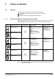
5.1.3 Special cases Special cases which are not covered by the Cerberus guidelines, or not in sufficient detail, and the causes of which lie in the fire hazard, the type of detector used, room geometry, room utilization, or the ambient conditions, require individual treatment. It may be necessary to determine the number of detectors and their locations by carrying out fire tests with measuring detectors and the corresponding measuring equipment. Planning symbols for fire detection systems (ISO/DIS 6790.
5.2 Smoke detectors 5.2.1 Influence of room height As the room height increases, so smoke density decreases because the quantity of smoke is distributed throughout a greater volume of air. h 3 Room height (Accumulation of heat) h 2 h 1 Open fire Fig. 11 Decrease in smoke density and smoke distribution with increasing room height The higher the room, the further away from the ceiling the detector must be mounted.
h3 Room height (Accumulation of heat) h2 h1 Smoldering fire Fig.
open fire smouldering fire AM Small monitoring area because: - room height ~3m - the detection of smaller incipient fires (both open and smouldering fires) is possible by means of smoke detectors on the ceiling. open fire smouldering fire AM> AM>> Large monitoring area because: - room height ~6m - the detection of open incipient fire (smouldering fire often only at the point of transition to open fire) is possible by means of smoke detectors on the ceiling.
5.2.2 Monitoring area per smoke detector The monitoring area (AM) is determined as a function of room height and the fire danger. Room height h [m] 25 20 15 12 10 9 8 7 6 5 4 3 2 3 1 2 1 AM [m2] 10 20 30 40 50 60 70 80 90 100 110 120 130 140 150 160 Monitoring area per smoke detector Degree of danger 1 little fire danger 2 moderate fire danger 3 major fire danger Fig.
5.2.3 The influence of exchange of air In artificially ventilated rooms the spread of smoke is disturbed. The greater the exchange of air the more the smoke particles are continuously carried away so that a uniform smoke concentration cannot be formed. As the amount of smoke is reduced and varies from place to place this leads to a reduction in sensitivity of the fire detection system. This can be partly compensated for by reducing the monitoring area and increasing detector sensitivity.
5.2.4 Maximum detector spacing (s) The maximum permissible distance from detector to detector or detector to wall depends on the chosen monitoring area AM. In principle a detector monitors a circular area. The maximum distance from detector to detector as defined by Cerberus is approximately the diameter of this circle. The square based on this diameter has a larger area than the selected monitoring area AM.
Reduced detector spacing between detectors to maintain A M Fig. 17 below shows the symmetrical distribution of detectors maintaining the permissible detector spacing and the monitoring area AM. d’ AM S/2 S max. detector spacing between detectors utilized s + 1.2 ǸA M Fig. 17 Distribution of detectors 12m (s) 6m (s/2) 8.3m (d’) A 400m2 4.15m (d’/2) 16.6m 4.15m (d’/2) 6m (s/2) 24m Fig. 18 Example AM 100m2 If for reasons of room geometry, or due to obstacles which prevent detector mounting (e.
5.2.5 Minimum detector spacing The distance from the detectors to the walls, fittings and stored goods may not be smaller than 0.5m except in corridors, ducts and other similar parts of a building with a width of less than 1m. If there are joists or beams, or, e.g. air conditioning ducts under the ceiling which are closer to the ceiling than 0.15m, then the lateral distance must be at least 0.5m. ≤15cm ≥0.5m ≥0.5m Fig. 19 Distances between detectors and walls, joists and fittings 5.2.
5.2.7 Roof structures Roof structures which are connected to the room to be monitored and whose surface area exceeds 10% of the total ceiling area, or providing this portion of the ceiling is >AM, must be regarded as separate rooms. Otherwise they need not be taken into account. Roof structure Fig.
5.2.8 Ceiling vents With ceiling vents (Cupolux, domed vents, dampers etc) detectors must be mounted in the vicinity of the vents providing the distribution of the vents, the monitoring area and the maximum distance between detectors permit this. ~40cm Fig. 23 Detector arrangement with unilateral ceiling ventilation ~40cm Fig. 24 Detector arrangement with bilateral ceiling ventilation 33 Fire & Security Products Siemens Building Technologies Group e432d 06.
5.2.9 Galleries Basically galleries or similar structures which do not allow smoke to pass should be treated in the same way. The degree to which smoke can penetrate trellis-work must be judged on the basis of the section on «Grid pattern dropped ceilings». Detectors must be provided beneath galleries which do not permit smoke penetration, providing: b >¼s whereby «s» must be calculated from the monitoring area in relation to room height beneath the gallery. 1/ 3 2/ 3 h b Fig.
5.2.10 Grid pattern dropped ceilings Dropped ceilings in the form of grids, trellis-work, or slats, e.g. for decoration purposes, to act as a screen or to support light fittings, influence the spread of smoke and heat. The degree to which grid pattern dropped ceilings allow smoke penetration varies according to the size of the grid openings and the type of fire, i.e. open fire or smouldering fire. Void Grid pattern Position A h Ceiling opening Position B Room monitoring I, II, III Fig.
5.2.11 Ventilated / air conditioned rooms Basically speaking, the fire detection system must be planned so that even when ventilation is switched on, monitoring is guaranteed. Smoke detectors used for room monitoring may not be installed in the path of the fresh air current of air conditioning and ventilation systems. Fresh air: Fresh air supply laterally on the wall, through grilles: Detector position at least 1.5m distance from air inlets. ≥1,5m Fig.
~1m2 seal off Fig. 32 Detector arrangement with fresh air ceiling vents covering a large area Return air: Point-type return air ceiling vents (diffusers etc.): Do not mount detectors in front of return air vents, rather in the turbulence zone. Fig. 33 Detector position with point-type return air vents Return air vents distributed over the ceiling surface normal detector arrangement Fig.
Return air grille in the wall directly below the ceiling: Detectors must be mounted in front of the return air grille Fig. 35 Detector arrangement with lateral return air P Fig. 36 Return air vents in the wall near the floor: In addition to the detectors on the ceiling, monitoring of the return air duct with the air-sampling unit ASD-duct detector unit is recommended 38 Fire & Security Products Siemens Building Technologies Group e432d 06.
5.2.12 Ventilation ducts Fresh air duct In order to prevent smoke-logging when fire breaks out in an air conditioning or ventilation system (e.g. motor or filter fire) the air-sampling unit ASD-duct (with F smoke detectors) must obviously be installed immediately after the equipment concerned on the outgoing side. Fig.
Tips on installation: The distance to duct change of direction or change of cross-sectional area must be approx. 1.5 times duct circumference Air sampling tubes should as far as possible be in the centre of the duct Good accessibility for service work Recommendation: Provide service hatches immediately next to the ASD-Duct Minimum duct depth: The tubes may not be shortened to less than 15 cm. Each tube must have at least 6 air holes (if necessary drill additional holes). Replace the end plug. 5.2.
5.2.14 Vertical installation shafts In vertical installation shafts, detectors must be mounted at a maximum distance apart of 8m as there is a danger that in spite of the collector plate the smoke will go past the detector. A smoke detector must always be mounted at the highest point of the shaft and in front of each horizontal fire-proof seal. 0,6m 0,5m Collector plate 0.3m2 Fig. 40 Detector arrangement in vertical installation shafts 5.2.
Ceilings with N ≤0.2 are regarded as flat ceilings (see section 5.3 «Detectors on flat ceilings»). If a ceiling (or roof) has surfaces with different slopes, e.g. north light roofs, then the least steep slope applies providing it is not less than ½s and therefore can be ignored. If both parts of the ceiling are steeper than ½s, then each part can be treated separately. Moderate slope: N1 N2 h’ h b1 0, 2 t hȀ + v 0.5 b1 b2 0, 2 t hȀ + v 0.5 b2 Fig. 43 Ceiling slopes N1 = N2 >0,2 ≤0.5 (see section 5.
N2 h’ h b2 b1 N 2 + hȀ + u 0.2 b2 Fig. 45 Asymmetrical ceiling with N2>0.2 Ceilings with N >0.2 are regarded as sloping ceilings (see section 5.4 «Detectors on sloping ceilings»). 5.3 Smoke detectors on flat ceilings 5.3.1 Distance from the ceiling Detectors must be installed at a level below where heat accumulates so that smoke can reach them unhindered. They must be spaced from the ceiling according to the table within the limits shown.
5.3.2 Monitoring area per detector Room height h [m] 25 20 15 12 10 9 8 7 6 5 4 3 2 3 1 2 1 AM [m2] 10 20 30 40 50 60 70 80 90 100 110 120 130 140 150 160 Monitoring area per smoke detector 1 little fire danger 2 moderate fire danger 3 major fire danger Fig. 48 Monitoring area per detector with flat ceilings 5.3.3 Maximum detector spacing Monitoring area AM [m2] 160 140 120 s + 1, 2 ǸA M 100 80 60 40 20 0 s [m] 0 2 4 6 8 10 12 14 16 max. detector spacing (s) Fig.
5.3.5 Room space A >AM Increase of AM in rooms with an area of max. 1.33 AM If the area of the room to be monitored is no more than 1/3 larger than the monitoring area per smoke detector, the monitoring area AM may also be 1/3 larger. Under such conditions, thanks to smoke accumulation 1 detector is sufficient for room monitoring. Detector spacing s in relation to the increased monitoring area must be maintained.
Detector distribution Variant 1: Begin with the length Variant 2: Begin with the width 1. Number of detectors (M) in lengthwise direction l: width b: M l + sl + 55 + 4, 58 å 5 12 2. Effective detector spacing in lengthwise direction l: s + l + 55 + 11m 5 Ml 35 Mb + b s + 12 + 2.9 å 3 width b: s b + b + 35 + 11.70m 3 Mb 3. Max. reference measurement without exceeding AM in the width: lengthwise: 4. Number of detectors (M) in width b: length l: A s bmax. + sM + 100 + 9.10m 11 l b M b + s max.
Monitoring area AM [m2] 180 160 140 120 s l + 1.6 ǸA M 100 80 60 40 20 0 s [m] 0 2 4 6 8 10 12 14 16 18 20 Maximum detector spacing (s) Fig. 53 Increased detector spacing Example: Monitoring area chosen AM 80m2 ½sl sl ½sl 5m <½s 7m 14m 7m Fig. 54 Increased detector spacing ½s + 1, 2 Ǹ80 + 5.36m + 5.4m 2 i.e. the room width is <«½s» and the lengthwise spacing may not exceed sl. s l + 1.6 ǸA M + 1.6 Ǹ80 + 14.
One detector must always be installed at corridor junctions. ≤15m ≤15m ≤15m Fig. 56 Detector arrangement at a corridor junction 5.3.7 Joists Minimum distance detector joist Joists obstruct the spread of smoke. The minimum distance joist detector is 0.5m. ≥50cm Fig.
Ratio of joist height to room height h’ Joist height h Room height Fig. 58 Room height and joist height Ratio joist height/room height = hȀ h A ratio of h/h’ >0.3 counts as a room division, i.e. the joist must be regarded as a wall. Joists with h’ ≥10cm can be ignored with the exception of the minimum spacing. Ceilings with suspended structures or fixtures, e.g. air conditioning ducts, the upper edges of which are not closer than 15cm to the ceiling should be treated as flat ceilings.
Ratio Ratio AU AM hȀ h -0.05 * 0.06-0.1 0.16-0.2 0.21-0.25 0.26-0.3 K P K P K P K P K P K P - 0.1 0.9 P1 0.9 P2 0.9 P2 0.8 P2 0.8 P2 0.8 P2 0.11 - 0.2 0.9 P1 0.9 P3 0.8 P3 0.7 P4 0.6 P4 0.6 P5 0.21 - 0.3 0,9 P1 0.8 P4 0.7 P4 0.6 P4 0.5 P4 0.5 P7 0.31 - 0.4 0.9 P4 0.8 P4 0.8 P4 0.7 P4 0.6 P5 0.5 P7 0.41 - 0.5 1,0 P4 0.9 P4 0.8 P5 0.8 P5 0.7 P5 0.6 P7 0.51 - 0.6 1.0 P1 0.9 P5 0.9 P5 0.8 P5 0.8 P5 0.7 P7 0.
Solution: 1. Calculate the ratio hȀ + 1 + 0.25 4 h 2. Calculate the ratio AU + 24 + 0.3 80 AM Ratio Ratio AU AM hȀ h -0.05 * - 0.1 0.06-0.1 0.16-0.2 0.21-0.25 0.26-0.3 K P K P K P K P K P K P 0.9 P1 0.9 P2 0.9 P2 0.8 P2 0.8 P2 0.8 P2 P1 0.9 P3 0.8 P3 0.7 P4 0.6 P4 0.6 P5 0.11 - 0.2 0.21 - 0.3 0.9 P1 0.8 P4 0.7 P4 0.6 P4 0.5 P4 0.5 P7 0.31 - 0.4 0.9 P4 0.8 P4 0.8 P4 0.7 P4 0.6 P5 0.5 P7 0.41 - 0.5 1.0 P4 0.9 P4 0.8 P5 0.8 P5 0.
Corrected monitoring area AM [m2] 160 140 120 s + 1.2 ǸA Mk 100 80 60 40 20 0 s [m] 0 2 4 6 8 10 12 14 16 Max. detector spacing (s) Fig. 61 Maximum detector spacing Maximum detector spacing must always be chosen in the longitudinal direction of the inter-joist areas so that detector spacing is reduced at right angles to the joists (obstruction of smoke spread). Oblong inter-joist areas with a ratio of h’/h ≥0.1 promote smoke spread in the longitudinal direction.
Example: AM 100m2 / AU 120m2 8m 8m 8m 8m 4m 6m 24m 12m 6m 4m 40m Fig. 63 Example of detector arrangement on ceilings with joists (AU >0.9 AM) Width of inter-joist area <½s ≥¼s h’/h ≤0.1 Distribute as for flat ceilings, however, maintain minimum space between detector and joist of 0.5m. h’/h >0.1 Maximum detector spacing is increased in the longitudinal direction because smoke spread is promoted in this direction. s l + 1.
The required number of detectors (M = A/AM) are distributed on the joists so that s or ½s is not exceeded. 31.9m 2.9m Example: AM 100m2 35m Fig. 65 Example of detector arrangement on a ceiling with joists (AU >0.9AM) Frequently the number of joists prevents symmetrical distribution. 26.1m 2.9m Example: AM 100m2 35m Fig. 66 Example of an unsymmetrical detector arrangement on a ceiling with joists (AU >0.9AM) 54 Fire & Security Products Siemens Building Technologies Group e432d 06.
5.4 Smoke detectors on sloping ceilings 5.4.1 Smoke channelling Sloping ceilings tend to channel smoke towards the ridge where we find the heaviest concentration of smoke. For this reason the basic area to be monitored AM and detector spacing are increased. Fig. 67 Smoke channelling on a sloping ceiling 5.4.
5.4.3 Detector spacing in the vicinity of the ridge In order that smoke can reach the detector unimpeded, the detector must be installed in the vicinity of the ridge below the level at which warm air accumulates. When dealing with ceiling structures with varying angles of slope, the longer of the two sides is decisive. Additional rows of detectors on the slope of the ceiling (with the exception of non-insulated ceilings which in fact form the slope of the ceiling) need not be spaced.
5.4.4 Reference figure for determining the required number of rows of detectors Instead of the maximum detector spacing s, the reference figure z is used which takes into account the effect of smoke channelling with sloping ceilings. Monitoring area AM [m2] 180 160 145 140 120 z + 0.75 ǸA Mk 100 80 60 40 20 0 z [m] 0 1 3 2 4 5 6 7 8 9 10 Fig. 72 Reference figure z for determining the required number of rows of detectors Fig.
The number and arrangement of rows of detectors parallel to the ridge is determined taking into account the slope of the ceiling N1 and N2 and the comparison of the two parts of the building width b1 and b2 with the reference figure z. With very narrow buildings, the ratio room height to joist depth is taken into consideration as an additional criterion. In Table Fig. 75 the various criteria for the comparison are shown horizontally and vertically.
Application example: + z = 9m + See detector arrangement «Flat ceilings with joists» h1 9m - hȀ ≥ 0, 3 h 5m ( ) 15m h 4m - N 1 + 0, 83 4m b 1)b 2 u z 2 b1, b2 z 5m + 0, 33 15m 5m N2 + 15m b2 6m b1 b1, z b2 ≤z a + 1/2b2 ≤z b + 1/3b2 ≤z c + b2>z, 2/3b2 ≤z d + 1/2b2 ≤z e + 2/5b2 ≤z f + 1/3b2 ≤z g + 2/3b2>z, 1/2b2 ≤z h + 1/3b2 ≤z i + 1/2b2>z, 2/5b2 ≤z k + l + - 2/3b1 ≤z + - 1/2b1 ≤z - 2/5b1 ≤z - 1/3b1 ≤z * - Key: - - - * + C D N1 <0,5 N2 <
5.4.6 Symmetrical arrangement of detectors 1 row of detectors in ridge (Result from Fig. 75) b The minimum number of detectors M is calculated with A/AM. The result is then rounded up to the nearest figure. 1/2x x The greatest possible detector spacing x at the ridge depends on the monitoring area A and full building width b and may not exceed 2z. Fig.
3 rows of detectors (result from Fig. 75) b1 b2 The minimum number of detectors M is calculated with A/AM. For a practical detector arrangement the result must be corrected acc. to the following table: Result Detectors required M 1-3 3* 4-5 5 6-8 8 9 - 11 11 12 - 14 14 15 - 17 17 18 - 20 20 etc. etc.
4 rows of detectors with no row of detectors in the ridge (result from Fig. 75) b2 b1 The minimum number of detectors M calculated with A/AM. The result is then rounded up to the nearest figure which is divisible by 4. 1/2x x l My My My My 1 Detector spacing x is: x + 4 M Fig. 79 Longitudinal arrangement of detectors with 4 rows of detectors with no row of detectors in the ridge 62 Fire & Security Products Siemens Building Technologies Group e432d 06.
5 rows of detectors (result from Fig. 75) b1 b2 The minimum number of detectors M is calculated with A/AM. For a practical detector arrangement the result must be corrected according to the following table whereby AM is slightly exceeded in borderline cases: Result Detectors required M 1-5 5* 6-7 7 8 - 13 12 14 - 18 17 19 - 24 22 25 - 29 27 etc. etc.
5.4.7 Asymmetrical arrangement of detectors 1 row of detectors as for symmetrical gable roof (result from Fig. 75) 2 rows of detectors (result from Fig. 75) b1 b2 The minimum number of detectors is calculated with A/AM. The result is then rounded up to the nearest uneven number. 1/2x x x l x x Mx The number of detectors Mx in the ridge is: Mx + M * 1 2 The number of in the lateral row is: My = Mx + 1 Detector spacing is: x + 1 My Fig.
3 rows of detectors with a row of detectors in the ridge (result from Fig. 75) b1 b2 The minimum number of detectors M is calculated with A/AM. For a practical arrangement the result must be corrected according to the following table: Result Detectors required M 1-3 3* 4 4 5-7 7 8 - 10 10 11 - 13 13 14 - 16 16 17 - 19 19 etc. etc.
3 rows of detectors with no row of detectors in the ridge (result from Fig. 75) b1 b2 The minimum number of detectors M is calculated with A/AM. The result is then rounded up to the nearest figure divisible by 3. 1/2x l x Detector spacing x is: x + 3 1 M Fig. 83 Longitudinal arrangement of detectors with 3 rows of detectors with no row of detectors in the ridge 66 Fire & Security Products Siemens Building Technologies Group e432d 06.
4 rows of detectors (result from Fig. 75) b1 b2 The minimum number of detectors M is calculated with A/AM. For a practical detector arrangement the result must be corrected acc. to the following table: Result 1-4 5-6 7 - 10 11 - 15 16 - 19 20 - 24 25 - 28 etc. Detectors required M 4* 6 10 14 18 22 26 etc.
5.5 Heat detectors 5.5.1 No spacing from the ceiling Unlike smoke detectors, heat detectors are mounted at the highest point of the ceiling. Fig. 86 Heat detector arrangement at the highest point of the ceiling 5.5.2 Ceiling structures / Sloping ceilings The monitoring area and the detector arrangement is determined according to the slope of the ceiling. For practical reasons the slope of the ceiling is not given in degrees but as a ratio of height to length of slope.
5.5.3 Heat channelling With sloping ceilings, heat travels across the slope of the ceiling to the highest point. This creates a concentration of heat in the ridge. For this reason the basic monitoring area AM and detector spacing are increased. Fig. 88 Flow of heat to the highest point on the ceiling 5.5.4 Monitoring area and maximum detector spacing The temperature increase at the ceiling directly above the seat of the fire falls by the square of the room height.
5.5.6 Minimum detector spacing The distance between detectors and walls, fixtures and fittings and stored goods may not be less than 0,5m, except for corridors, ducts and similar parts of buildings of less than 1m in width. If there are joists, beams or e.g. air conditioning ducts running below the ceiling, which are closer to the ceiling than 0.15m, then detectors must be spaced at least 0.5m laterally from these structures. ≤0.15m ≥0.5m ≥0.5m Fig. 90 Spacing detectors from installation fittings 5.5.
5.5.8 Raised roof structures Raised roof structures which are connected to the room to be monitored and whose surface area exceeds 10% of the total ceiling area, or as long as this part of the ceiling is AM, must be regarded as separate rooms. If not, they can be disregarded. Roof structure Fig. 92 Room with raised roof structure 5.5.9 Ceiling ventilation With ceiling ventilation (Cupolex, «mushroom» vents etc.
5.5.10 Galleries Basically, galleries or similar structures which suppress the influence of heat flow should be treated in the same way. The permeability of the flow of heat through trellis constructions must be assessed as under the section «Grid pattern dropped ceilings» (5.5.13). Detectors must be provided beneath galleries without heat flow permeability provided: b >1/4s whereby the monitoring area s must be based on the room height beneath the gallery. 1/ 3 2/ 3 h b Fig.
5.5.11 Ventilated / air conditioned rooms Detectors for room monitoring may not be installed in the path of the fresh air current from air conditioning and ventilation systems. Perforated ceilings which provide ventilation must be sealed around the detectors. ~1m2 abdichten Fig. 97 Sealing a perforated ceiling 5.5.12 Narrow rooms / corridors In narrow rooms or corridors not wider than 3m, detector spacing may in general be increased to 10m.
5.5.13 Grid pattern dropped ceilings Dropped ceilings which form a grid pattern, e.g. for purposes of decoration, to diffuse light, or to support light fittings, influence the spread of heat. The heat permeability of grid pattern dropped ceilings varies according to the percentage of space taken up by the openings and the nature of the openings themselves. Void Position B Position A h Ceiling opening Grid pattern Monitoring categories I, II, III Fig.
If they have to be taken into account refer to the following table Fig. 101: Maximum monitoring area Size of inter-joist area Mount one detector in each 20m2 >12m2 8 - 12m2 6 - 8m2 4 - 6m2 <4m2 IJA* 2. IJA 3. IJA 4. IJA 5. IJA 30m2 >18m2 12 - 18m2 9 - 12m2 6 - 9m2 <6m2 IJA 2. IJA 3. IJA 4. IJA 5. IJA Heat detector * IJA = Inter-joist area Fig. 101 Detector arrangement where joists have to be taken into account 5.5.15 Sloping ceilings (N >0.2) If the slope of the ceiling N is >0.
0.2 - 0.5m Fig. 104 Detector arrangement in the ridge with varying slope of ceiling For north light roofs, detectors can be mounted as for roofs with joists where the roof structures are less than 1/4s provided hȀ + ≤ 0.3 . h The monitoring area AM must in this h case be calculated as for a flat ceiling. 76 Fire & Security Products Siemens Building Technologies Group e432d 06.
5.6 Flame detector S2406 The description and planning are contained in document e164 «Infrared flame detector» in the DS24 manual, section 2. 5.7 Linear smoke detector DLO1191 The description and planning are contained in document e1276 «Linear smoke detector» in the DS11 manual, section 3. 5.8 Air sampling smoke detection The description of and planning for the following products are contained in the corresponding documents.
5.9 Manual call points 5.9.1 Number and locations Manual call points must be installed where they are clearly visible along escape routes, e.g. Exits Corridors Staircases Lift foyers Entrance halls Hose cabinets particularly hazardous areas at intervals of not more than 40m. ≤40m <40m ≤40m ≤40m >40m Manual call point Hose cabinet Fig. 105 Locations of manual call points along escape routes 78 Fire & Security Products Siemens Building Technologies Group e432d 06.
Fig. 106 Locations of manual call points in rooms with increased fire danger Zones of manual call points without mechanical self hold may not be operated via intermediate alarm memories. 5.9.2 Mounting height In general manual call points should be mounted at a height of 1.5 to 1.7m from the floor. This prevents unwanted operation (e.g. confusion with light switches in the dark). They may be mounted at a lower height when built into hose cabinets or control desks. 1.50 - 1.70m F Fig.
6 Detector zones and detection lines 6.1 Terminology A detector zone is a group of detectors connected in one detection line, for which an indicator (fire location indicator) is provided at the control unit. The detection line is the monitored electrical transmission line which connects the fire detectors to the control unit. 6.2 Formation of detector zones 6.2.1 Automatic fire detectors The entire monitoring zone must be divided up into detector zones.
Zone Attic Zone Ground floor south ÒÒÒÒ ÒÒÒÒ ÒÒÒÒ ÒÒÒÒ Fire wall Zone upper floor Zone Ground floor north Zone Staircase Fig.
Detectors installed in raised floors, dropped ceilings, cable, air conditioning and ventilation systems, should form a special zone of their own, or it must be possible to determine in a simple way, e.g. using external response indicators, in which area detectors have responded.
Zone A F F Upper floor F Fire department access F F F Basement floor Zone B Fig. 113 Formation of zones of manual call points in staircases with more than two basement levels 6.2.3 Fire control installations Frequently, in the event of fire, installations such as dampers, ventilation systems, lifts etc. have to be automatically activated. In order that this is possible from the zone control outputs at the control unit, the size of zone must be must be determined according to these conditions. 6.
6.4 Temporary, local switching off of fire detectors Fire detectors can be switched off by means of the time switch (AMT 12C) for between 18 minutes and 12 hours and automatically switched on again upon expiry of the selected switch-off period. Within the same detector zone (MS7/MS9) any two detectors or several detectors in sequence can be switched off.
7 Fire detection system control unit 7.1 Location of control unit The control unit must be located according to the following criteria: In the immediate vicinity of the main entrance of the area to be monitored, or the entrance used by the fire department in an emergency. If this is not practical, then a display and operating terminal should be located here and connected to the control unit by a primary wire.
7.3 Centralized or decentralized arrangement of the control unit in large fire detection systems Cerberus control units are designed for a certain maximum number of detector zones. Their specifications and configuration possibilities are laid down in separate planning documents (Manual ZH4, CZ control units).
8 Alarm 8.1 General Alarm must enable rapid intervention of fire-fighting forces. Basically the Cerberus alarm concept (CAC) should be used. See Planning guidelines, document e804, Manual ZH4.1 and document e1089, Manual CS11. 87 Fire & Security Products Siemens Building Technologies Group e432d 06.
9 Fire control installations 9.1 General Installations which form part of the fire protection concept can be actuated automatically by the fire detection system.
9.1.3 Control unit in TEST mode If the control unit is in «TEST» mode, fire control installations may only be actuated if the fire detection system has to give a genuine alarm, e.g. when a manual call point is actuated. 9.1.4 Testing fire control installation actuation It must be possible to test the correct functioning fire control installations without their being actuated. Switch-off key Actuation - - External control + Performance check + Switch-off indicator Fig.
10 Avoiding deceptive alarms 10.1 General Deceptive alarms can be largely avoided by choosing a suitable type of detector, response sensitivity, detector arrangement and by taking into account ambient conditions. The fire detection system’s immunity to deceptive alarms is more important than high response sensitivity. The following possibilities are just a few examples of how deceptive alarms can be avoided. Decide in each case on which measures are the most suitable. 10.2 Possible measures 10.2.
D/T-type detectors Do not install detectors in places where, due to natural or operational sources of heat, the ambient temperature can cause the detector to respond. no direct solar radiation on the detector install at a distance from equipment which radiates heat such as baking ovens, hot air blowers, hot steam etc.
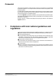
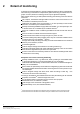
11 Procedure for planning a fire detection system It is assumed that fire protection fire planning has been carried out according to Cerberus document 431 and that the fire detection system has to be planned as part of the all-round fire protection measures. 1 Compliance with local national guidelines and regulations - Establish which regulations must be complied with. Such regulations take priority over Cerberus guidelines.
Keyword index C Complete monitoring, 2 D Deceptive phenomena, 5 E Exchange of air, 28 Explanation of abbreviations, 92 F Fire control installations, 88 Fire load, 3 Fire phenomena, 21 Fire resistance, 4 Fire risk reduction, 4 Fire spread, 6 Fixed extinguishing system, 4 O Open incipient fire, 5 P Partial monitoring, 2 Planning symbols, 23 Point-type detector, 14 S Smoke distribution, 24, 25 Smouldering fire, 6 Smouldering incipient fire, 5 Sources of ignition, 3 93 Fire & Security Products Siemens Bu
Siemens Building Technologies AG Alte Landstrasse 411 CH−8708 Männedorf Phone +41 1 − 922 61 11 Fax +41 1 − 922 64 50 www.cerberus.ch 94 Fire & Security Document no. Products e432d Siemens Building Technologies Group Edition 06.2002 Manual 06.