
User Manual


e432d
51
Fire & Security Products
Siemens Building Technologies Group
06.2002
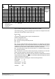
Solution:
1. Calculate the ratio
hȀ
h
+
1
4
+ 0.25
2. Calculate the ratio
A
U
A
M
+
24
80
+ 0.3
Ratio
A
U
Ratio
hȀ
h
A
U
A
M
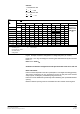
-0.05 * 0.06-0.1 0.11-0.15 0.16-0.2 0.21-0.25 0.26-0.3 >0,3
M
K P K P K P K P K P K P
- 0.1
0.9
P1 0.9 P2 0.9 P2 0.8 P2 0.8 P2 0.8 P2
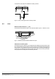
Treat as room
division i e the
0.11 - 0.2 P1 0.9 P3 0.8 P3 0.7 P4 0.6 P4 0.6 P5
division, i.e. the
joists forms a
0.21 - 0.3 0.9 P1 0.8 P4 0.7 P4 0.6 P4 0.5 P4 0.5 P7
j
o
i
s
t
s
f
orms
a
wall
0.31 - 0.4 0.9 P4 0.8 P4 0.8 P4 0.7 P4 0.6 P5 0.5 P7
wall
0.41 - 0.5 1.0 P4 0.9 P4 0.8 P5 0.8 P5 0.7 P5 0.6 P7
0.51 - 0.6 1.0 P1 0.9 P5 0.9 P5 0.8 P5 0.8 P5 0.7 P7
0.61 - 0.7 1.0 P1 0.9 P5 0.9 P5 0.9 P5 0.8 P7 0.8 P7
0.71 - 0.8 1.0 P1 1.0 P6 1.0 P7 0.9 P7 0.9 P7 0.9 P7
0.81 - 0.9 1.0 P6 1.0 P6 1.0 P7 1.0 P7 1.0 P7 0.9 P7
≥ 0.9 No reduction of the monitoring area, see page 51
A
U
= Inter-joist area h’ = Joist height
A
M
= Monitoring area h = Room height
* Ignore joists of <10cm!
K Correction factor
P Arrangement
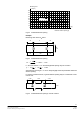
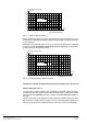
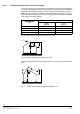
Fig. 60 Example of detector arrangement on ceilings with joists (A
U
≤0.9A
M
)
Read off K = 0.5 in Fig. 60. Multiply the monitoring area determined A
M
by this correction
factor, i.e.:
80m
2
x 0.5 = 40m
2
A
Mk
Guidelines for detector arrangement for inter-joist areas with a ratio of A
U
/ A
M
≤0.9
Basic information:
Detector location depends on the ratio of joist depth to room height and ceiling geometry.
The location of detectors can vary according to the size of inter-joist areas and their
shape (square, rectangular, predominantly long and narrow).
Detectors must be distributed symmetrically while maintaining max. permissible detector
spacing.
Maximum detector spacing must be recalculated from the reduced monitoring area.