
User Manual


4 Planning Cerberus D100 Stage III
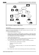
4.3.3.3 Thermal printer FD60
Designation Remark < 30 m > 30 m
Thermal printer
FD60
X
Transformer
24 V / 24 V 50 W
Needed for the power supply to the thermal printer FD60 X
Connector line 120 cm (exposed at one end) X
Table 16: Thermal printer FD60 – component overview
The following is required as an alternative to the connector line V24265-K131-A1:
• 1x 9-pin SUB-D plug with housing, cable LIYCY 8x1x0.14
• 1x 9-pin SUB-D socket with housing
(only when connecting the printer to SOP-S24230-F130-A4)
You will find order numbers for output devices and printers in the appendix.
See the section ‘Ordering table for output devices/printers’ on page 81.
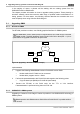
4.3.4 Printer protocol converter (DPU)
General information
The new printer type ‘Default printer (via DPU)’ is launched in SIGMAPLAN V2.6. This printer
works as an IBM Proprinter (not a laser printer) with 8 bits. The DPU is connected to the V.24
interface of the SIGMANET control and indicating panels, the M-module or the S-module.
It must be possible set the serial interface of the danger alarm system to the following values:
baud rate 4800, 8 bits; interface type V.24 or TTY, half-duplex active (all characters will be
forwarded: 0-255 at 8 bits, 0-127 at 7 bits).
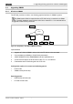
Planning
Designation Remark < 30 m < 1,000 m
Default printer IBM Proprinter; character set 1 (default)
Line-by-line printout (not a laser printer)
X X
TTY/V.24 converter
V.24 > 30 m
X
DPU
Connecting cable, DPU→ printer
Standard Centronics can be ordered with the printer
X X
Plug-in power supply 12-27 V plug DIN 45232 + terminal on outside X 1) X
SUB-D socket 9-pin with housing X 2) X 2)
SUB-D plug 25-pin with housing X
LIYCY 8x1x0.14 Cable X X
RS 232 isolator X
1) Can be used, otherwise power supply from danger alarm system in a separate cable
2) When connecting DPU to SOP operating panel S24230-F130-A4
Table 17: Printer protocol converter DPU – component overview
Multifunctional Danger Alarm System D100 Stage III 63 / 118
Order No. A24205-A334-B846 – Edition 1