
User Manual

6 Appendix
Danger alarm system Cerberus D100
Proj ect: ............................................................................
.........................................................................................
Resp. Memo Date Name
Sheet
Node K __ Slot no. __ Cabinet no. __
Date
Author
Order cod e: .................................................................................
Bran ch: ........................................................................................
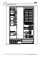
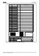
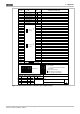
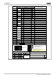
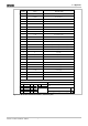
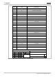
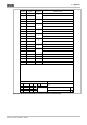
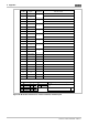
Allocation plan: Digital input connection board
Terminal
34 APL
DE ___ Cable Information on data input
1
2
3
4
5
6
7
8
9
10
11
12
13
14
15
16
17
18
19
20
21
22
23
24
25
26
27
28
29
30
31
32
33
34
- UB
+ UB
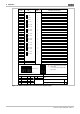
Floor cabinet
Mark the slot for the APL with an 'X'
Connection layer
Wall cabinet
1 - 32
33 - 64
65 - 96
97 - 128
129 - 160
161 - 192
193 - 224
225 - 256
257 - 288
289 - 320
321 - 352
353 - 384
385 - 416
417 - 448
449 - 480
481 - 512
513 - 544
545 - 576
o.
u.
o.
u.
o.
u.
o.
u.
o.
u.
o.
u.
o.
u.
o.
u.
o.
u.
u. = X1 = uppermost head plug cable
in the module
l. = X2 = lowermost head plug cable
in the module
1
1
Figure 38: DE connection board, allocation plan (digital input)
86 / 118 Planning Instructions
Order No. A24205-A334-B846 – Edition 1