
Automobile Parts User Manual

D-4
Distributed I/O System DP/ASi Link
EWA 4NEB 710 6055-02b
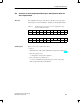
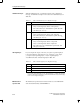
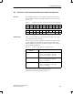
With the identification byte, you define the structure of the configuration
message. You will find a description of the value of the identification byte in
Table D-3.
Table D-3 Value of identification byte in configuration message
Value Meaning
43
H
Input data only
in byte 16, the length byte stands for the input data
there follow three bytes of manufacturer-specific data: 00
H
3C
H
40
H
, (bytes 17 to 19).
83
H
Output data only
in byte 16, the length byte stands for the output data
there follow three bytes of manufacturer-specific data: 00
H
3C
H
40
H
, (bytes 17 to 19).
C2
H
Input and output data
in byte 16, the length byte stands for output data
in byte 17, the length byte stands for input data
there follow two bytes of manufacturer-specific data: 3C
H
40
H,
(bytes 18 and 19).
If you use inputs and outputs on the ASi, you require a separate length byte
for both input data and output data. If you use only inputs or only outputs,
you require only an input length byte or only an output length byte.
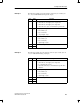
You will find the value of the I/O length byte in Table D-4.
Table D-4 Value of the I/O length byte in configuration message
Value Meaning
00H 1 byte of data with byte consistency
L L
0F
H
1
16 bytes of data with byte consistency
1
If you specify an input length byte or an output length byte, you define automatically
in doing so that at least one data byte is present. You can therefore set bytes in the range
from 1 to 16 for inputs and outputs.
The manufacturer-specific data are intended for later use of the DP/ASi link
with extended functionality within SIMATIC S7.
Identification byte
I/O length byte
Manufacturer-
specific data
Configuration Message