
Automobile Parts User Manual


3-2
Distributed I/O System DP/ASi Link
EWA 4NEB 710 6055-02b
3.1 Summary of Configuration Options
PROFIBUS-DP presents you with different configuration options for combin-
ing the PROFIBUS-DP and the 24 V power supply of the devices. The fol-
lowing Table 3-1 shows the different options.
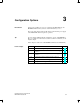
Table 3-1 Configuration options
Power Supply Connector for Device’s
Internal Power Consumption
Configuration Refer to
Configuration with power supply con-
Configuration without T connector Section 3.2
g p pp y
nector
Configuration with T connector Section 3.3
Configuration with programmer
connector
Section 3.6
Configuration with several power supply connectors (the degree of expansion is
limited with a PS connector)
Section 3.4
Configuration without power supply
connector (every L2 station has a sepa-
Configuration without power supply con-
nector
Section 3.5
(y p
rate power supply)
Configuration with programmer
connector
Section 3.6
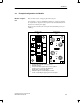
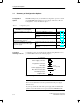
Configuration options are described in the following using illustrations for a
possible installation. We use the following legend:
PS
PS
cntr
T connector
Power supply connector
Programmer connector
Bus cable
Power supply (PS) cable
Bus cable incl. PS cable
Adapter cable
2-core
5-core
3-core (see note)
PG
Terminating resistor
Figure 3-1 Legend
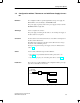
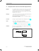
Note
The 2-core bus cable must not be incorporated between the power supply
unit and a load.
If you incorporate the bus cable in the power supply cable, an inadmissible
spur line occurs. Data transfer is no longer assured in the PROFIBUS-DP.
Configuration
options
Legend for
following sections
Configuration Options