
Instruction manual

Electrical connection
67
TNT 35/7-24V
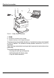
8 Electrical connection
The Safety Sensor may only be connected and integrated into the machine's
control system by an appropriately qualified person.
ª Observe the safety notes (see chapter, "Safety", page 13) and technical data
(see chapter, "Technical data", page 60).
ª Ensure that the voltage supply and all connected input and output current
circuits have safe mains isolation in acc. with IEC 742.
The safety-related switching output is redundantly configured.
ª Basically you always connect both safety-related switching outputs (OSSDs)
with the machine's switch-off circuit so that they are both separately fully
effective for switching off the dangerous movement (see chapter, "Integrating
the Safety Sensor into machine control system", page 73).
You may not use the alarm outputs for switching safety-relevant signals.
8.1 Electrical power supply
(see chapter, "Electrical power supply", page 62)
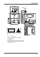
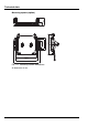
8.2 Interfaces
The Safety Sensor has two interfaces:
• Interface X1 for connection with the control system
• Interface X2 for connection with PC or laptop
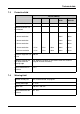
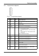
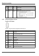
Interface Type Function
X1 SUB-D15
• Power supply
• Switching lines and signal lines
X2 SUB-D9 Configuration interface and data interface:
• Parameter configuration
• Protective field definition and warning field definition
• Data transfer and measured value transfer
• Diagnostics