SIMATIC IPC627C 1 ___________________ Introduction 2 ___________________ Description SIMATIC Industrie PC SIMATIC IPC627C 3 ___________________ Application planning 4 ___________________ Mounting 5 ___________________ Connecting 6 ___________________ Commissioning Getting Started 7 ___________________ Troubleshooting 8 ___________________ Dimensional drawings A ___________________ Appendix 09/2011 A5E02669077-03
Legal information Legal information Warning notice system This manual contains notices you have to observe in order to ensure your personal safety, as well as to prevent damage to property. The notices referring to your personal safety are highlighted in the manual by a safety alert symbol, notices referring only to property damage have no safety alert symbol. These notices shown below are graded according to the degree of danger.
Table of contents 1 Introduction................................................................................................................................................ 5 2 Description................................................................................................................................................. 7 3 4 5 6 7 2.1 Exterior design ...............................................................................................................................7 2.
Table of contents A Appendix.................................................................................................................................................. 45 A.1 Guidelines and declarations........................................................................................................ 45 A.2 Certificates and approvals........................................................................................................... 46 A.3 Service and support .......................
Introduction 1 Purpose of this document This Getting Started documentation contains all the information you need for commissioning and using the SIMATIC IPC627C. Scope of validity of this document This documentation is valid for all supplied versions of the SIMATIC IPC627C. SIMATIC IPC627C, Operating Instructions The operating instructions are available on the supplied "Documentation and Drivers" CD. To view and print the operating instructions, run Start and follow the instructions on the screen.
Introduction SIMATIC IPC627C 6 Getting Started, 09/2011, A5E02669077-03
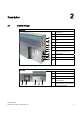
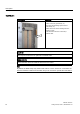
2 Description 2.
Description 2.
Description 2.2 Operator Controls 2.2 Operator Controls On/Off switch On/Off switch Description Switch the device on using the on/off switch. This requires that the BIOS Setup entry "After Power Failure" is set to "Power On". WARNING The on/off switch does not isolate the device from the mains! When the switch is in 0 position (Off), the device is still supplied with mains voltage in order to generated the internal auxiliary voltage for the power supply.
Description 2.2 Operator Controls On/off button On/off button Description The on/off button has three functions: - Switch on the PC (press briefly 1x) - Shut down the operating system and PC (press briefly 1x) - Switch off the PC without shutting down the operating system (press and hold more than 4 seconds) = hardware reset. CAUTION Data may be lost when the PC performs a hardware reset.
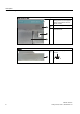
Description 2.3 Connection elements 2.3 Connection elements Interfaces Arrangement of the interfaces on the front of the device Item Description Description ① DVI/VGA DVI/VGA connection for CRT or LCD monitor with DVI interface, VGA via DVI/VGA adapter ② Compact Flash card Slot for Compact Flash card ③ COM Serial V.24 port ④ USB 2.
Description 2.3 Connection elements The interfaces available on the device can be uniquely identified based on their numbering. This numbering may deviate, however, from the numbering performed by the operating system. Interfaces for connecting operator panels / displays Arrangement of the interfaces ① LVDS display interface for TFT displays up to 1024 x 768 pixels ② Access to 2nd LVDS display interface for TFT displays up to 1280 x 1024 ③ USB 2.
Description 2.3 Connection elements AC power supply Position of the IEC power connector Description IEC power connector to AC power supply of the device. The maximum permitted power range is 100 VAC to 240 VAC.
Description 2.
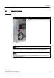
Description 2.4 Status displays 2.
Description 2.4 Status displays Status display The status display consists of two 7-segment displays and two three-color LEDs.
Application planning 3.1 3 Transport Despite the device's rugged design, its internal components are sensitive to severe vibrations or shock. You must therefore protect the PC from severe mechanical stress when transporting it. You should always use the original packaging for shipping and transporting the device. CAUTION Risk of damage to the device! When transporting the PC in cold weather, it may be submitted to extreme variations in temperature.
Application planning 3.3 Device identification data 3.3 Device identification data The device can be clearly identified with the help of this identification data in case of repairs or theft. Enter the following data in the table below: ● Serial number: The serial number (S VP...) is found on the rating plate.
Application planning 3.4 Ambient and environmental conditions 3.4 Ambient and environmental conditions When you plan your project, take note of the following points: ● Observe the climatic and mechanical environmental conditions specified in the technical specifications of your operating instructions. ● This device was designed for use in a normal industrial environment.
Application planning 3.5 Permitted mounting positions 3.5 Permitted mounting positions PC mounting positions according to UL60950-1/UL508/EN60950-1/CSA22.2 No. 60950-1 An inclination of ± 20° is permitted for all approved mounting positions.
Application planning 3.5 Permitted mounting positions Additional PC mounting positions according to UL508/CSA 22.2 No. 142 An inclination of ±15° is allowed in this mounting position. Position 4 (interfaces facing down) CD/DVD drive may not be operated. Position 5 (interfaces facing up) CD/DVD drive may not be operated. Note CD/DVD and floppy drives cannot be operated in this position. The CD drawer opens upward or downward which can lead to mechanical damages in the drawer mechanism.
Application planning 3.
4 Mounting 4.1 Installing the device The device is particularly suitable for installation in consoles, switch cabinets and switchboards. WARNING Function test while installing the device in machines or execute systems Following the results of a risk analysis, additional protection equipment on the machine or the system is necessary to avoid endangering persons.
Mounting 4.2 Installing the device with mounting brackets 4.2 Installing the device with mounting brackets Screw-mounting the brackets Two angle brackets are included in the product package. You can attach these to the PC enclosure using six M3 x 6 mm screws. ① Mount the brackets onto the device using the included M3 screws with a max. insertion depth of 5 mm (included in package).
Mounting 4.
Mounting 4.3 Installing the device with the vertical mounting kit 1. Remove the equipotential bonding screw ① from the device and attach it with the vertical 2. Attach the vertical mounting plate with four M4 screws and three M3 screws to the device mounting plate ②. Note Please note the information in the following section Permitted mounting positions (Page 20).
Mounting 4.4 Installing the device with the vertical mounting kit for PC port access from the front 4.4 Installing the device with the vertical mounting kit for PC port access from the front The optional vertical mounting kit allows space-saving installation of the device.
Mounting 4.4 Installing the device with the vertical mounting kit for PC port access from the front 1. Secure the vertical mounting plate ① on the device using five M4 screws: two screws on top ② and three (not shown in figure) on the bottom of the device. Note Please note the information in the following section Permitted mounting positions (Page 20).
Connecting 5.1 5 Connecting peripherals Note before connecting NOTICE Connect only peripheral devices approved for industrial applications to EN 61000-6-2:2005. Note Hot-plug peripheral devices (USB) may be connected while the PC is in operation. CAUTION Peripheral devices that are incapable of hot-plugging may only be connected after the device has been disconnected from the power supply. CAUTION Strictly adhere to the specifications in the manuals for the peripheral devices.
Connecting 5.2 Connecting the 100 - 240 V AC Power Supply 5.2 Connecting the 100 - 240 V AC Power Supply Note before connecting the device Note The varying voltage power supply module is designed for operation on 120/230/240 V AC networks. The setting of the voltage range takes place automatically. WARNING Do not connect or disconnect power and data cables during thunderstorms.
Connecting 5.2 Connecting the 100 - 240 V AC Power Supply Localized information For countries other than the USA and Canada: 230 V supply voltage This device is equipped with a safety-tested power cable which may only be connected to a grounding outlet. If you choose not to use this cable, you must use a flexible cable of the following type: Min 18 AWG conductor cross-section and 15-A / 250-V shockproof connector.
Connecting 5.2 Connecting the 100 - 240 V AC Power Supply Connecting How to connect the device to the 120 V AC / 230 V AC power supply 1 Ensure that the ON/OFF switch is in "0" position (Off) when you plug in the power cord in order to avoid unintentional startup of the device. 2 Connect the IEC connector 3 Connecting the power cord to the power socket 4 Fasten the cable with the supplied power plug latch ①, if necessary.
Connecting 5.3 Connecting the (24 V) DC power supply 5.3 Connecting the (24 V) DC power supply Note before connecting the device WARNING Only connect the device to 24 V DC power supply systems which meet the requirements of a safe extra-low voltage (SELV); in addition, a protective conductor must be connected. The conductors must withstand the short-circuit current of the 24 V DC power source, so that a short-circuit will not damage the cable. Only connect cables with a minimum crosssection of 1.
Connecting 5.3 Connecting the (24 V) DC power supply Connecting Steps for connecting the device to the 24 V DC power supply 1 Ensure that the ON/OFF switch is in the '0' (OFF) position to prevent unintentional startup of the device when connecting it to the 24 V power supply. 2 Switch off the 24 V DC power source. 3 Insert the DC power plug. ① DC 24 V ② ground ③ protective conductor 4 Fasten the cable with the supplied power plug latch, if necessary.
Connecting 5.4 Connecting equipotential bonding 5.4 Connecting equipotential bonding The equipotential bonding terminal (M4 thread) on the device (large surface, large-area contact) must be connected to the PE conductor of the cabinet or system in which the device is to be installed. The minimum cross-section is 5 mm2.
Connecting 5.
Commissioning 6.1 6 Requirements for commissioning CAUTION Risk of damage to the device! Make sufficient allowances for the device to acquire room temperature before you put it into use. If condensation has developed on the device wait at least 12 hours before you switch it on. Note The device features an off/off switch and an on/off button. By default, the BIOS Setup entry "After Power Failure" is set to "Power On". This means that the device is turned on using the on/off switch.
Commissioning 6.2 Basic commissioning - initial startup 6.2 Basic commissioning - initial startup The PC operating system is automatically set up the first time you switch on the device. Procedure: 1. Set the ON / Off switch to I position (On). The PC performs a POST. During the self-test, this message appears: Press go to SETUP Utility Press go to Bootmanager 2. Wait until this message is cleared, then follow the instructions on the screen. 3. Type in the Product Key as required.
7 Troubleshooting 7.1 General problems This chapter provides you with tips on how to localize and troubleshoot frequently occurring problems. Problem Possible cause Remedy The device is not operational There is no power supply to the device. Check the power supply, the network cable and the power plug. Check if the On/Off switch is in the correct position. Device is being operated outside the specified ambient. conditions Check the ambient conditions.
Troubleshooting 7.1 General problems Problem Possible cause Wrong time and/or date on the PC. Remedy 1. Press during the boot sequence to open BIOS Setup. 2. Set the time and date in the setup menu. Although the BIOS setting is OK, the time and data are still wrong. The backup battery is dead. Replace the backup battery. USB device not responding. The USB ports are disabled in your Use a different USB port or enable the port. BIOS.
Dimensional drawings 8.
Dimensional drawings 8.1 Dimensional drawings of the device Figure 8-2 Dimensional drawing for mounting without angle bracket NOTICE When mounting devices with optical drives or WinAC backup batteries change the fitting depth.
Dimensional drawings 8.
Dimensional drawings 8.1 Dimensional drawings of the device NOTICE When mounting devices with optical drives or WinAC backup batteries change the fitting depth.
A Appendix A.1 Guidelines and declarations Notes on CE marking The following applies to the SIMATIC product described in this documentation: EMC directive The devices fulfill the requirements for the EC directive "2004/108/EEC Electromagnetic Compatibility" and are designed for the following applications as per the CE marking: Fields of application Requirement for Emitted interference Immunity to interferences Residential, business and trade areas and small businesses.
Appendix A.2 Certificates and approvals A.2 Certificates and approvals Information on the rating plate Note The currently valid approvals are to be found on the device rating plate. ISO 9001 certificate The Siemens quality management system for all production processes (development, production and sales) meets DIN ISO 9001:2000 requirements. This has been certified by DQS (the German society for the certification of quality management systems). Q-Net certificate no.
Appendix A.2 Certificates and approvals EMC USA Federal Communications Commission Radio Frequency Interference Statement This equipment has been tested and found to comply with the limits for a Class A digital device, pursuant to Part 15 of the FCC Rules. These limits are designed to provide reasonable protection against harmful interference when the equipment is operated in a commercial environment.
Appendix A.2 Certificates and approvals cULus approval, Hazardous Location +$= /2& CULUS Listed 7RA9 IND. CONT. EQ. FOR HAZ. LOC. Underwriters Laboratories Inc., to ● UL 508 (Industrial Control Equipment) ● CSA C22.2 No. 142 (Process Control Equipment) ● ANSI/ISA 12.12.01 (Hazardous Location) ● CSA-213 (Hazardous Location) APPROVED for Use in ● Cl. 1, Div. 2, GP. A, B, C, D T4A ● Cl. 1, Zone 2, GP.
Appendix A.3 Service and support A.
Appendix A.
Index 2 24 V DC power supply, 14 Connecting, 33 A AC power supply, 13 B Bottom, 8 C CE marking, 45 Certificates, 46 Certifications, 46 Certifications and approvals, 19 COA label, 18 Compact Flash card, 11 Connecting 24 V DC power supply, 33 Peripherals, 29, 45 Power supply 120/230 V AC, 30 Connection components, 11 D Declaration of Conformity, 45 Device Unpacking, 17 Diagnostics Troubleshooting, 39 Dimensional drawings Device, 41 Display interfaces, 12 DVI/VGA port, 11 E EMC, 47 EMC directive, 45 Equi
Index P Peripherals, 29 Connecting, 45 Permitted mounting positions, 20 Power supply, 13, 30 IEC power connector, 13 PROFIBUS/MPI interface, 11 R Rating plate, 18, 46 Rear view, 7 Restart, 38 S Screw-mounting the brackets, 24 Serial interface, 11 Side view, 8 Status display, 16 Status displays, 15 Supply voltage, 31 T Transport, 17 Troubleshooting/FAQs, 39 U USB interface, 11 V Vent slots, 19 Vertical mounting, 24 Front interfaces, 27 VGA port, 11 SIMATIC IPC627C 52 Getting Started, 09/2011, A5E026