
Operating instructions

Guidelines for Installing Networked Automation Systems in Buildings
7-38
SIMATIC NET Twisted-Pair and Fiber-Optic Networks
C79000-G8976-C125-02
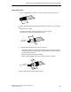
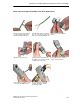
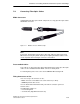
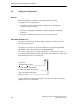
Installing the IE FC Outlet RJ-45
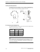
The FC Outlet RJ-45 can be installed on a rail or screwed to a mounting surface.
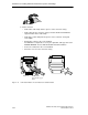
The Outlet RJ-45 can also be installed as a PG socket behind a wiring cubicle wall.
If this is required, nuts must be fitted in the openings on the sides.
23 mm
22 mm
90 mm
approx. 25 mm
4 x M4 screw,
length to suit
particular installa-
tion
4 x square nut M4
DIN 562 or
4 x hexagon nut A M4
DIN 439
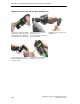
Pin Assignment of the FC Outlet RJ-45
The assignment between the contacts of the RJ-45 jack and the insulation piercing
terminals for the FC TP cable is as follows:
RJ-45 Pin
Insulation Piercing Terminals
Number
Number Wire Color
1 1 yellow
2 3 orange
3 2 white
6 4 blue
Note
The FC TP cable between two FC Outlet RJ-45 devices must always 1:1. In other
words, terminal 1 must be connected terminal 1, terminal 2 to terminal 2 etc. If
crossovers are required, this should always be done with one of the patch cables
connected to the RJ-45 jack.