
Operating instructions


Network Topologies with OSM/ESM
Industrial Ethernet OSM/ESM
30
C79000-Z8976-C068-04
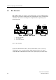
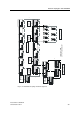
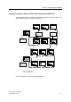
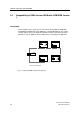
The connection between two network segments is on two separate paths. Two of the
OSMs/ESMs in a ring are connected together via a connecting cable (ITP-XP standard
cable 9/9 with a maximum length of 40 m) and inform each other of their operating
states. One of these OSMs/ESMs is assigned the redundant function using the DIP
switch setting "Stby on" (standby slave). The other OSM takes over the function of the
standby master (DIP switch setting "Stby off").
Immediately following the failure of the main transmission path, the standby slave
enables the redundant path. If the main path is OK again, the standby master informs
the standby slave. The main path is enabled and the redundant path disabled again.
The reconfiguration time of the redundant ring coupling is less than 0.3 s.
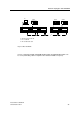
Port Assignment in the Standby Mode
On the standby master and standby slave
only port 1
(standby port) can be used for
the coupling to the neighboring ring. Ports 2 - 6 can be used just as normal OSM
ports.
With network management, it is also possible to configure ports other than port 1 as
standby ports (See also OSM/ESM Network Management User Manual)
Simultaneous Standby and Redundancy Manager Operation
A standby master or standby slave can adopt the function of a redundancy manager at
the same time.
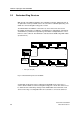
Replacing the Standby Master During Operation
When replacing a standby master during operation, the following order is necessary to
prevent an interruption on the network:
1. Remove the terminal block for the power supply on the standby master
2. Remove the signal lines and the standby connecting cable from the standby
master.
3. Connect the signal lines to the standby connecting cable on the replacement
device.
4. Plug in the terminal block for the power supply on the replacement device.
When replacing a standby slave, no special measures are necessary.