
Operating instructions

Configuring Networks
3-22
SIMATIC NET Twisted-Pair and Fiber-Optic Networks
C79000-G8976-C125-02
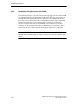
Note
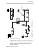
If redundant rings are attached to a star coupler structure, when checking the
configuration, the redundant ring must be segmented to produce a worst-case bus
structure. To do this, the shortest connection from the star coupler to one of the
two adjacent OLMs is interrupted.
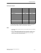
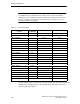
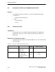
Table 3-5 Checking the Example
Node 1
--> Node 3
Cable Length
(as Example)
Delay Equivalent Variability Value
Node 1 140 m 0 BT
Node 1 - OLM 1 100 m
OLM 1 (ITP/FO) 360 m 6 BT
OLM 1 - OLM 2 400 m
OLM 2 (FO/FO) 260 m 3 BT
OLM 2 - OLM 3 250 m
OLM 3 (FO/ITP) 360 m 6 BT
OLM 3 - ECTP 3 80 m
ASGE (ECTP3/ECFL2) 225 m 5 BT
ECFL 2 - OLM 7 100 m
OLM 7 (FO/FO) 260 m 3 BT
OLM 7 - OLM 6 200 m
OLM 6 (FO/FO) 260 m 3 BT
OLM 6 - OLM 5 300 m
OLM 5 (FO/FO) 260 m 3 BT
OLM 5 - OLM 4 300 m
OLM 4 (FO/ITP) 360 m 6 BT
OLM 4 - Node 3 100 m
Node 3 140 m 0 BT
Sum of cable length 1830 m
Sum of the delay equivalents 2625 m
Totals 4455 m 35 BT
The path between node 1 and node 3 is correctly configured; in other words, all the nodes
attached to the redundant ring can exchange data via the star coupler and the line
segment connected to ECTP 3.