
Technical data

Interface to the User Program in the S7-200 CPU
2-11
SIMATIC NET CP 243-2 AS-i Master
C79000-G8976-C142/02
2.3.4 Control Byte (Output Register 8DO)
Meaning for the User Program
The user program controls the data exchange with the CP 243-2 using this
register.
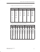
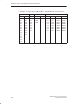
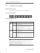
Structure of the Control Byte
Bit 7 Bit 6 Bit 5 Bit 4 Bit 3 Bit 2 Bit 1 Bit 0
PLC_RUN ASI_COM BS5 BS4 BS3 BS2 BS1 BS0
Description of the Bits
Table 2-2
Bit
Value Meaning
BS0..BS5 0 ... 63
dec.
Bank select bits for changing the bank in the analog module
(see Section 2.5).
ASI_COM 0/1 Job bit for the AS-i command interface (see Section 5.1).
PLC_RUN In the STOP mode of the S7-200 CPU, the CP must send defined values to
all AS-i slaves (see Chapter 3). Since the AS-i slave data are transferred
via the analog area and the S7-200 CPU does not set this area to ’0’ when
it changes from RUN to STOP, the CPU mode must be signaled to the
CP 243-2 using the PLC_RUN bit as follows:
0 Signal to the CP 243-2 that the S7-200 CPU is in the STOP
mode.
The CP 243-2 sends ’0’ to all AS-i binary slaves. The analog
value transfer to analog output slaves is interrupted. The
S7-200 CPU sets the bit automatically to “0” at a change from
RUN to STOP.
1 Signals to the CP 243-2 that the S7-200 CPU is in the RUN
mode.
The CP 243-2 sends the content of output bank 0 to all AS-i
slaves (see Section 2.4). The user program must set this bit to
“1” during startup (first scan).
Do not set the PLC_RUN bit permanently to “1” with the
S7-200 operating system functions such as “CPU
configuration/setting the outputs” or “force outputs”.