
Technical data
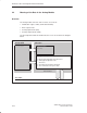

Interface to the User Program in the S7-200 CPU
2-14
SIMATIC NET CP 243-2 AS-i Master
C79000-G8976-C142/02
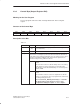
2.4.2 Error Register in the Analog Module
Meaning for the User Program
With this register, the CP 243-2 signals errors to the user program.
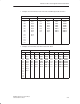
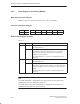
Structure of the Error Register
Bit 7 Bit 6 Bit 5 Bit 4 Bit 3 Bit 2 Bit 1 Bit 0
0 0 0 0 0 APF 0 CER
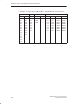
Bit Description/Range of Values
Table 2-3
Bit
Value Meaning
CER 0 AS-i configuration correct (only in the protected mode)
The “CER” LED is off
1 AS-i configuration error (only in the protected mode)
This indicates a difference between the slave configuration
detected on the AS-i cable and the desired configuration
configured on the CP 243-2.
The “CER” LED is lit (see Section 1.8.1 Status Display of the
CP 243-2).
APF 0 AS-i voltage correct
The “APF” LED is off.
1 AS-i Power Fail.
This indicates that the voltage supplied on the AS-i cable by the
AS-i power supply unit is too low or there is a complete power
outage.
The “APF” LED is lit (see Section 1.8.1 Status Display of the
CP 243-2).
Note
The “CER” bit indicates configuration errors only in the protected mode. In the
configuration mode, the “CER” bit is always “0”.
The “CER” LED, on the other hand, indicates configuration errors both in the
configuration mode and in the protected mode.