47HPreface SIMATIC Industrial Software Engineering Tools TSdapterI Properties of the TS Adapter II 1 ______________ SIMATIC Industrial Software Engineering Tools TS Adapter II Manual 2 Scope of delivery ______________ 3 Requirements for operation ______________ Hardware configuration of the TS Adapter II 4 ______________ Working with the TS Adapter II 5 ______________ TS Adapter II on the MPI/DP/PPI network 6 ______________ 7 Firmware update ______________ 8 Error diagnostics ______________ A Appendi
Safety Guidelines Safety Guidelines This manual contains notices you have to observe in order to ensure your personal safety, as well as to prevent damage to property. The notices referring to your personal safety are highlighted in the manual by a safety alert symbol, notices referring only to property damage have no safety alert symbol. These notices shown below are graded according to the degree of danger.
Preface Purpose of this manual This manual provides a complete overview of the TS Adapter II and supports you in the installation and commissioning of the software and hardware. It explains the requirements for operation and hardware installation, and how to connect the adapter to MPI/DP/PPI networks. It is intended for programmers and persons involved in configuring, commissioning, and servicing of automation systems.
Preface Additional support If you have any questions relating to the products described in this manual, and do not find the answers in this documentation, please contact your Siemens partner at our local offices. You will find information on who to contact at: http://www.siemens.com/automation/partner A signpost to the documentation of the various SIMATIC products and systems is available at: http://www.siemens.de/simatic-tech-doku-portal You will find the online catalog and order system at: http://mall.
Table of contents Preface ...................................................................................................................................................... 3 1 Properties of the TS Adapter II .................................................................................................................. 7 1.1 Properties.......................................................................................................................................7 1.2 Function ..............
Table of contents 6.3 6.3.1 6.3.2 Use on networked system........................................................................................................... 42 Connection to networked S7 systems......................................................................................... 42 Connection in the ring ................................................................................................................. 42 7 Firmware update........................................................
Properties of the TS Adapter II 1.1 1 Properties Overview The USB connection of the TS Adapter II is compatible with USB V1.1 and complies with the specifications for a "Low-Powered" USB device. The TS Adapter II supports hibernate mode. When used in an S7-300 system, the TS Adapter II does not loop through the I/O bus. Therefore, the TS Adapter II should preferably be mounted in the last position on the rack. 1.
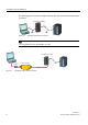
Properties of the TS Adapter II 1.2 Function The following figures show the TS Adapter II-Modem with direct connection and with modem connection: 76 $GDSWHU ,, 0RGHP 86% Figure 1-1 03, TS Adapter II with direct connection Note You can operate only one TS Adapter II on a PC.
Properties of the TS Adapter II 1.3 Performance features 1.3 Performance features You can operate the TS Adapter II on MPI networks, PROFIBUS networks, and homogeneous PPI networks. The TS Adapter II corresponds basically to a PC Adapter USB. Baud rates and bus profiles The following table shows the baud rates supported by the TS Adapter II on various network types.
Properties of the TS Adapter II 1.
2 Scope of delivery Overview The scope of delivery of both SIMATIC TS Adapter II variants includes: ● "SIMATIC TeleService Edition" CD with software and documentation ● USB cable (5 m) ● 24 V power plug ● MPI cable (0.8 m) ● Slide for DIN rail mounting You can use the MPI cable to connect the TS Adapter II to MPI networks, homogeneous PPI networks, or PROFIBUS (DP) networks.
Scope of delivery 12 TS Adapter II Manual, 06/2008, A5E00272728-03
Requirements for operation 3.1 3 Software requirements Overview For working with the TS Adapter II, you need a PC with an MS Windows operating system and the software (device driver) for the TS Adapter II. The list of supported operating systems is included in the latest Readme file for the TS Adapter II software. To assign parameters and to establish a remote connection, you will need: ● SIMATIC TeleService TeleService V6.0 or higher is required for parameter assignment of the TS Adapter II.
Requirements for operation 3.3 Installation 3.3 Installation Types of installation You can install the TS Adapter II as follows: ● On the mounting rail of the S7-300 (see section "Installation on mounting rail"). Make sure that you use the lost slot of the mounting rail since the TS Adapter II does not loop through the signals of the I/O bus, or ● On the DIN rail (see section "Installation on DIN rail"). WARNING The mounting rail or DIN rail on which the TS Adapter II is installed must be grounded.
Requirements for operation 3.3 Installation 3.3.1 Installation on mounting rail Procedure The various module installation steps are explained below. 1. Place the TS Adapter II at the of the profile rail. Unlike S7-300 modules, the TS Adapter II does not require a bus connector. Hook the TS Adapter II onto the rail (1), slide it over until it reaches the module on the left (2), and swing it down into place (3). 2. Hand-tighten the screws on the TS Adapter II.
Requirements for operation 3.3 Installation 3.3.2 Installation on a DIN rail Requirement The DIN rail is mounted. Tools required: 3-mm screwdriver The enclosed slide must be inserted into the rear panel of the TS Adapter II from below. Figure 3-2 Slide for installing the TS Adapter II on a DIN rail Installing TS Adapter II 1. Hook the TS Adapter II onto the DIN rail. 2. Swivel the TS Adapter II back until the slide engages audibly.
Requirements for operation 3.3 Installation Uninstalling TS Adapter II 1. You can see the bottom end of the slide on the underside of the TS Adapter II. Using a screwdriver, press against the slide in the direction of the DIN rail and pull the slide downward, thus loosening the engagement mechanism. 2. Swivel the TS Adapter II forward out of the DIN rail.
Requirements for operation 3.
Hardware configuration of the TS Adapter II 4.1 4 Connections Below are two figures showing the different adapters and their respective connections.
Hardware configuration of the TS Adapter II 4.
Hardware configuration of the TS Adapter II 4.2 LEDs on the TS Adapter II 4.2 LEDs on the TS Adapter II Overview The TS Adapter II is equipped with the following LEDs: ● 3V operating voltage ● Bus fault ● USB ● DCD ● RX/TX 76$ ,, 02'(0 6) 6,(0(16 %86) '& 9 5; 7; '&' 86% Figure 4-3 LEDs of the TS Adapter II SF Group error BUSF Bus fault DC3V 3V operating voltage RX/TX RX/TX DCD DCD USB USB Startup characteristics All LEDs are switched on when power is restored.
Hardware configuration of the TS Adapter II 4.2 LEDs on the TS Adapter II The LEDs on the TS Adapter II have the following meaning: Designation Color Meaning SF Red Group error: Lights up when the TS Adapter II detects an error situation on the modem interface or the MPI/DP interface. This LED also is also lit during a firmware download operation. BUSF Red Bus fault: This LED is switched off when the TSP Adapter II has been incorporated in the MPI/DP network without errors.
Hardware configuration of the TS Adapter II 4.3 Power supply 4.3 Power supply The automation system supplies power to the TS Adapter II via the supplied MPI cable or the power socket for an external power supply. The TS Adapter II requires only 24 V voltage (see appendix "General technical specifications"). No current is drawn from the USB interface. DANGER Only connect the TS Adapter II to devices with power supplies with limited power (SELV). The MPI/DP interface is electrically isolated.
Hardware configuration of the TS Adapter II 4.4 MPI/DP interface 4.4 MPI/DP interface Connector assignment The MPI/DP socket has the following pinout: Signal description Pin. No. Short description Meaning Input/ output 1 NC Not connected - 2 M24V For 0 V line of the 24 V supply; supplies the adapter electronics via a DC/DC converter (PC potential area) Input 3 LTG_B Data line B Input/output 4 RTS_AS RTS_AS, control signal for receive data stream.
Hardware configuration of the TS Adapter II 4.4 MPI/DP interface MPI cable UL cable, AWM 2464, 80°C, 300V, 28 AWG, VW-1 Figure 4-4 MPI cable, 0.8 m with 9-pin sub D connectors Signal assignment 6KLHOG 1& 1& 1& 3 9 /7*B$ 6KLHOG 6XE ' SLQ Figure 4-5 TS Adapter II Manual, 06/2008, A5E00272728-03 0 9 1& 576$6 0 9 /7*B% 1& 1& 6XE ' SLQ MPI cable (0.
Hardware configuration of the TS Adapter II 4.5 USB interface 4.5 USB interface Interface assignment Top view of the USB socket: Signal description Pin no. Signal 1 +5V 2 -Data - Differential signal 3 +Data + Differential signal 4 Ground Ground Power supply CAUTION If multiple USB devices are operating on your PC, this can affect the data transmission times.
Hardware configuration of the TS Adapter II 4.6 RS232 interface 4.6 RS232 interface The TS Adapter II has a COM interface configured as an RS232C interface, which is used solely for connecting external modems. Standard modems, ISDN terminal adapters, or GSM radio modems can be connected to and operated on the COM interface. Note The firmware detects the insertion of an external modem and switches automatically from internal to external modem operation.
Hardware configuration of the TS Adapter II 4.7 Power plug for power supply 4.7 Power plug for power supply Supply system connection The 24 V supply voltage can be delivered via the MPI/DP interface cable or the power cord for the power supply. The 24 V infeed socket is located at the bottom of the module front panel.
Hardware configuration of the TS Adapter II 4.7 Power plug for power supply Note For information on how to connect the power supply, refer to section "Connecting the TS Adapter II".
Hardware configuration of the TS Adapter II 4.8 Modem interfaces 4.8 Modem interfaces 4.8.1 TS Adapter II-Modem variant The TS Adapter II-Modem variant has an analog modem interface with a 6-pin RJ12 connector. The supplied analog phone cable is connected to this interface. This allows the modem to be connected to a phone socket. The length of the cable is 3 m.
Hardware configuration of the TS Adapter II 4.8 Modem interfaces 4.8.2 Technical specifications of the analog modem Modem modules of the SIM family are used on the TS Adapter II. These modules are small, highly integrated, state-of-the-art data communication units. Properties / technical specifications ● ITU Transmission Standards: V.21, V.22, V.22 to, V.23, V.32, V.32 to, V.34, V.34x, K56flex, V.90, V.92 ● Error correction and data compression ● Supply voltage 3.3 V ● Serial interface V.
Hardware configuration of the TS Adapter II 4.8 Modem interfaces 4.8.3 TS Adapter II-ISDN variant The TS Adapter II-ISDN variant provides an S0 interface at the 8-pin RJ45 socket. Using the supplied ISDN phone cable, you can connect the TS Adapter II to an ISDN S0 socket. The length of the cable is 3 m. ISDN phone cable 5- 5- Note When inserting, grasp the cable just below the RJ45 connector. Make sure the RJ45 connector engages audibly.
Hardware configuration of the TS Adapter II 4.8 Modem interfaces Connector assignment and signal description RJ-45 Western plug Signal name Pin no.
Hardware configuration of the TS Adapter II 4.8 Modem interfaces 4.8.4 Technical specifications of the ISDN terminal adapter The TS Adapter II is equipped with a modular active ISDN terminal adapter, which is controlled with TTL signal levels via a serial interface.
Working with the TS Adapter II 5.1 5 Safety notices Qualified personnel The device may only be serviced by qualified personnel. Qualified persons are defined as persons who are authorized to commission, to ground and to tag circuits, equipment, and systems in accordance with established safety practices and standards.
Working with the TS Adapter II 5.3 Setting the PG/PC Interface 5.3 Setting the PG/PC Interface Procedure During installation of the software you are prompted to set the PG/PC interface. 1. In the "Set PG/PC Interface" dialog, check whether the following interface parameter has been assigned. The selection list must contain the entry: – TS Adapter If this is not the case, – click "Select..." to add/remove an interface. The "Install/Remove Interface" dialog box opens.
Working with the TS Adapter II 5.4 Connecting the TS Adapter II 5.4 Connecting the TS Adapter II Connecting to the PC 1. When prompted to do so, insert the supplied USB cable onto a USB interface of your PC. 2. Insert the other end of the USB cable onto the USB interface of the TS Adapter II. Connecting to the automation system 1. Insert the supplied MPI cable onto the TS Adapter II and tighten the screws. 2.
Working with the TS Adapter II 5.4 Connecting the TS Adapter II Connecting to the analog phone socket 1. Insert the supplied analog phone cable onto the TS Adapter II. 2. Plug the other end of the phone cable into your phone socket. Use the TAE plug adapter if necessary. Note You can operate the TS Adapter II-Modem on internal and public analog telecommunications networks (TNV-3 system). The insulating voltage between the phone side and the remaining electronics is rated for 250 V AC.
Working with the TS Adapter II 5.4 Connecting the TS Adapter II Reset button The TS Adapter II is equipped with a Reset button that you can use to reset the adapter parameter assignment to the default parameter assignment. This may be necessary if the adapter parameters in a remote system have been modified such that the TS Adapter II can no longer be reached via the phone connection. In this case, the operator of the remote system must hold the reset button down for approximately 2 seconds.
Working with the TS Adapter II 5.
TS Adapter II on the MPI/DP/PPI network 6.1 6 General information A maximum of 32 nodes can be connected to an MPI/DP/PPI network segment. The total cable length must not exceed 50 m. Multiple network segments can be combined using RS485 repeaters to form an overall network with a maximum of 127 nodes. The maximum data transmission rate in the MPI/DP network is 12 Mbps. The TS Adapter II supports transmission rates up to a maximum of 12 Mbps.
TS Adapter II on the MPI/DP/PPI network 6.3 Use on networked system 6.3 Use on networked system 6.3.1 Connection to networked S7 systems The following figure shows the connection to networked S7 systems (MPI network with 2 or more nodes). You use the supplied MPI cable to connect the TS Adapter II. 6 [ 6 \ 6 [ 76 $GDSWHU ,, 6XSSOLHG 03, FDEOH 6.3.
Firmware update 7 The TS Adapter II firmware can be updated as required, for example, after new features have been added. To update the firmware, proceed as follows: ● You will find the latest firmware and the firmware update tool on the Internet at: http://www.siemens.com/automation/simatic-cs ● Search for "TS Adapter II" under Product Support. ● Download the self-extracting exe file containing the available firmware and the firmware update tool to your PC. ● Extract the files to a local drive.
Firmware update 44 TS Adapter II Manual, 06/2008, A5E00272728-03
8 Error diagnostics To check the functioning of the LEDs, switch the operating voltage of the TS Adapter II off and back on. All LEDs are switched on when power is restored. After a few seconds, the LEDs are set according to the current operating state. Simple malfunctions that you can diagnose and correct in some cases are explained below. Error/cause Remedy SF and BUSF LEDs are lit • • • The assigned network parameters of the TS Adapter II are incorrect.
Error diagnostics 46 TS Adapter II Manual, 06/2008, A5E00272728-03
A Appendix A.1 Standards, Approvals, Certificates, Guidelines, Labels, and Declarations Note The currently valid approvals are to be found on the product rating plate. Safety requirements ● The TS Adapter II meets the requirements and criteria of the IEC 61131-2 standard. ● The IT interface is subject to the IEC 60950 standard. CE mark Our products conform to the requirements and safety objectives of the EC Directives listed below.
Appendix A.1 Standards, Approvals, Certificates, Guidelines, Labels, and Declarations EMC directive SIMATIC products are designed for industrial applications. Area of application Requirements Interference emission Industry EN 61000-6-4: 2007 Interference immunity EN 61000-6-2: 2005 Explosion protection directive Conforming to EN 60079-15:2005 and EN 60079-0:2006 (Electrical apparatus for potentially explosive atmospheres; Type of protection "n") II 3 G Ex nA II T3 ...
Appendix A.1 Standards, Approvals, Certificates, Guidelines, Labels, and Declarations cULus approval, Hazardous Location cULus Listed 7RA9 INT. CONT. EQ. FOR HAZ. LOC. Underwriters Laboratories Inc., to +$= /2& ● UL 508 (Industrial Control Equipment) ● CSA C22.2 No. 142 (Process Control Equipment) ● UL 1604 (Hazardous Location) ● CSA-213 (Hazardous Location) APPROVED for Use in ● Cl. 1, Div. 2, GP. A, B, C, D T4A ● Cl. 1, Zone 2, GP.
Appendix A.1 Standards, Approvals, Certificates, Guidelines, Labels, and Declarations FM approval Factory Mutual Approval Standard Class Number 3611, Class I, Division 2, Group A, B, C, D, T4A. Class I, Zone 2, Group II C, T4. WARNING Personal injury and property damage can occur. In potentially explosive atmospheres there is a risk of injury to persons or damage to property if you connect or disconnect a live electrical circuit, such as connectors, fuses, switches, when a TS Adapter II is in operation.
Appendix A.1 Standards, Approvals, Certificates, Guidelines, Labels, and Declarations Approval regulations The TS Adapter II modem is designed for connection to the analog public telecommunications network. In Germany, the device is connected by means of the supplied standard cable with TAE connector and N-coding. The TS Adapter II ISDN is designed for connection to the digital public ISDN network. Use the supplied standard ISDN cable for connection.
Appendix A.2 Customer Information for ACTA A.2 Customer Information for ACTA Customer Information for ACTA This equipment is compliant with Part 68 of the FCC regulations and requirements adopted by ACTA. The label on the right sideof this equipment also contains the product ID (US: CO4DT10B022B3V3 for the TS Adapter II-Modem respectively US:EVIDENANTSA2ISDN for the TS Adapter II-ISDN). This ID must be submitted to the telephone company on request.
Appendix A.3 General technical specifications A.3 General technical specifications What are the general technical specifications? The general technical specifications include: ● The standards and test values to which the TS Adapter II complies. ● The criteria by which the TS Adapter II was tested. TS Adapter II Order number TSA-II ISDN 6ES7 972-0CC35-0XA0 Order number TSA-II Modem 6ES7 972-0CB35-0XA0 Dimensions Approx. 125 x 110 x 40 mm Weight Approx.
Appendix A.3 General technical specifications Horizontal and vertical installation Comply with the general installation guidelines for SIMATIC. Cabinet installation is stipulated. You can install the TS Adapter II vertically or horizontally. The following ambient air temperatures are permitted: Vertical installation: 0 to 40 °C Horizontal installation: 0 to 60 °C Always install the TS Adapter II at the top or on the right.
Appendix A.3 General technical specifications A.3.1 Electromagnetic compatibility Definition of "EMC" Electromagnetic compatibility (EMC) is the capacity of an electrical installation to function satisfactorily in its electromagnetic environment without affecting that environment. WARNING Personal injury and damage to property may occur. Any installation of expansion units which are not approved for TS Adapter II may violate requirements and standards relating to safety and electromagnetic compatibility.
Appendix A.3 General technical specifications Sinusoidal Interference The table below shows the electromagnetic compatibility of the TS Adapter II in relation to sinusoidal interference. Table A-2 Sinusoidal Interference Sinusoidal interference Test values Degree of severity HF irradiation (electromagnetic fields) according to IEC 61000-4-3 10 V/m with 80% amplitude modulation of 1 kHz in the range from 80 MHz to 1000 MHz and 1.
Appendix A.3 General technical specifications A.3.2 Shipping and storage conditions Shipping and storage of modules The TS Adapter II surpasses the requirements of IEC 61131-2 with respect to transportation and storage conditions. The following specifications apply to TS Adapter II units that are transported and stored in their original packaging. Climatic conditions correspond to IEC 60721-3-3, Class 3K7 for storage and IEC 60721-3-2, Class 2K4 for transportation.
Appendix A.3 General technical specifications Mechanical environmental conditions The table below sets out the mechanical environmental conditions for the TS Adapter II in the form of sinusoidal vibrations. Table A-4 Mechanical environmental conditions Frequency range in Hz Test values 10 ≤ f < 58 0.075 mm amplitude 58 ≤ f < 500 9.
Appendix A.3 General technical specifications Climatic environmental conditions The TS Adaptor II may be used under the following climatic environmental conditions: Table A-6 Climatic environmental conditions Environmental conditions Permissible range Comments 0 to +60 °C Horizontal installation 0 to +40 °C Vertical installation Temperature Temperature change Max. 10 °C/h Relative humidity Max.
Appendix A.
Index A Adapter connections, 7, 19 Analog phone socket Connecting the adapter, 38 Approval regulations, 51 Automation system Connecting the adapter, 37 B Baud rates, 9 Bus profiles, 9 C CE mark, 47 Certifications and approvals, 47 Climatic environmental conditions, 59 Compatibility, 7 Connecting in the ring, 42 to a networked S7 system, 42 to a standalone system, 41 to the analog phone socket, 38 to the automation system, 37 to the external modem, 38 to the ISDN phone socket, 38 to the MPI/DP network, 41
Index O Operating conditions, 57 P PC Connecting the adapter, 37 Performance features, 9 Power supply, 23 Protection class, 59 R Requirements Hardware, 13 Software, 13 RTTE directive, 48 S Safety notices, 35 Safety requirements, 50 Scope of delivery, 11 Signal description, 25 Software, 35 Software requirements, 13 Stand-alone system Connecting the adapter, 41 T Technical specifications, 53 Test voltages, 59 Transmission rates, 41 TS Adapter II, 53 U Uninstalling, 17 Updating Firmware update, 43 USB c