Preface, Contents SIMATIC PC Panel PC 670 Panel PC 870 Start-Up Instructions Unpacking and Installing the Panel PC 670/870 1 Connecting and Switching On the Panel PC 670/870 2 Operating the Panel PC 670/870 3 Electromagnetic Compatibility 4 General information 5 Appendix This Start-Up Instructions manual is valid for the following units: Panel PC 670: Order Number 6AV77xx-... Panel PC 870: Order Number 6AV77xx-xC... and 6AV77xx-xD...
Safety Guidelines This manual contains notices which you should observe to ensure your own personal safety, as well as to protect the product and connected equipment. These notices are marked as follows according to the level of danger: Danger indicates an imminently hazardous situation which, if not avoided, will result in death or serious injury. Warning indicates a potentially hazardous situation which, if not avoided, could result in death or serious injury.
1Preface Purpose This Start-Up Instructions manual is a component part of the documentation for the SIMATIC Panel PC 670 and SIMATIC Panel PC 870 (subsequently referred to as Panel PC 670/870). This Start-Up Instructions manual contains the information for installation engineers and system operators necessary for the mechanical and electrical installation of the Panel PC 670/870 and starting it up.
Preface Release 11/02 Notation Different font formats simplify orientation within the text: The text on the screen of the operating unit is displayed in typewriter font. Inputs and outputs on the screen of the operating unit are displayed in italic typewriter font. Menu items, dialog names, tab controls and buttons of the operating system and the application are displayed in italic font. In context with menu items the complete path is always described.
Release11/02 Preface Customer and Technical Support Available worldwide: Nuremberg Johnson City Singapore SIMATIC Hotline Worldwide (Nuremberg) Worldwide (Nuremberg) Technical Support Technical Support (FreeContact) (fee-based, only with SIMATIC Card) Local time: Mon.–Fri. 8:00 to 17:00 Local time: Mon.–Fri. 0:00 to 24:00 Telephone: +49 (180) 5050-222 Telephone: +49 (911) 895-7777 Fax: +49 (180) 5050-223 Fax: +49 (911) 895-7001 E-Mail: techsupport@ ad.siemens.
Preface Release 11/02 SIMATIC Customer Support Online Services The SIMATIC Customer Support team offers you substantial additional information about SIMATIC products via its online services: • General current information can be obtained – In the Internet under http://www.siemens.com/simatic • Current Product Information leaflets, FAQs (Frequently Asked Questions), Downloads, Tips and Tricks can be obtained – In the Internet under http://www.siemens.
Contents 1 Unpacking and Installing the Panel PC 670/870 .............................. 1–1 1.1 1.2 1.3 2 3 Unpacking and Checking the Delivery Contents ............................................. 1–1 Installation of the Panel PC 670/870................................................................ 1–3 Installation of the Computer Unit.................................................................... 1–11 Connecting and Switching On the Panel PC 670/870 ..................... 2–1 2.1 2.2 2.3 2.
Contents Release 11/02 4 Electromagnetic Compatibility.......................................................... 4–1 5 General Information ........................................................................... 5–1 Appendix ...........................................................................................................
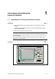
1 Unpacking and Installing the Panel PC 670/870 1.1 1 Unpacking and Checking the Delivery Contents Unpacking Step 1 • Check the packaging of the Panel PC 670/870 for visible signs of transport damage. If signs of transport damage are apparent, contact the transporting company responsible immediately. • Open the packing and unpack the contents. Note Do not dispose of the original packaging – save it for a future transportation of the Panel PC 670/870.
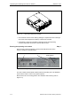
Unpacking and Installing the Panel PC 670/870 Figure 1–2 Release 11/02 View of the Panel PC 670 computer • Check that the content of the delivery package is complete and free of damage. Check the content against the "delivery contents" list enclosed. • If the delivery content is incomplete or damage, inform the transporting company responsible and set the contents aside unused.
Release 11/02 Unpacking and Installing the Panel PC 670/870 Also enter the Microsoft Windows "Product Key" of the "Certificate of Authenticity" (COA) in the table. The Product Key can be found on the unit on the power supply cover. The Windows Product Key is necessary should the operating system need to be reinstalled. SVP number MLFB number Microsoft Windows Product Key 1.
Unpacking and Installing the Panel PC 670/870 Release 11/02 Installation angle Step 4 Warning If the Panel PC 670/870 is installed in a position which is not permissible, all approvals complying with UL 1950 and EN 60950 are annulled. The Panel PC 670/870 is available in two different designs: • Panel PC 670/870 in a centralized design – computer and operating unit from one unit. • Panel PC 670/870 in a decentralized design – computer and operating unit are assembled spatially separated.
Release 11/02 Unpacking and Installing the Panel PC 670/870 2. Panel PC 670/870 in a decentralized design Only applies to the operating unit: +70° Figure 1–5 –20° Permissible installation angles for the Panel PC 670/870 in a decentralized design Vertical installation as well as deviations up to +70° to –20° in the indicated directions are permitted. The installation position for the computer is described in Chapter 1.3.
Unpacking and Installing the Panel PC 670/870 Release 11/02 Select installation cut-out Step 6 Apples to the computer in a decentralized design: No installation cut-out is required for the computer. Skip this working step. Applies to both centralized and decentralized designs: Select an appropriate installation area taking the installation notes and selected installation angle into account. Note Ensure sufficient air volume for heat transportation within the switching cabinet/panel.
Release 11/02 Unpacking and Installing the Panel PC 670/870 A1 ±1 L3 ±1 S1 ±1 S2 ±1 112 ±0.5 Clamp with grub screws L3 ±1 A2 ± 1 112 ±0.5 L2 +1 Drill hole for screw fixings 112 ± 0.5 56 ± 1 L5 ± 0.2 Pressure points for clamps L1 +1 S1 ±1 Rz 120 (in gasket area) *) *) S1 ±1 M6/∅ ∅7 Gasket area L4 ±0.2 min. 1.5 – max. 6 Operating units L1 (a) with key-based front panels: 10.4"-TFT / 12.1"-TFT 15.1"-TFT (b) with touchscreen front panels: 12.1"-TFT 15.
Unpacking and Installing the Panel PC 670/870 Release 11/02 Making the installation cut-out Step 7 Applies to both centralized and decentralized designs: Figure 1–7 below contains the dimensions for the installation cut-out for the Panel PC 670/870 or the operating unit in a decentralized design. 2 to 6 2 H+1 B+1 T+1 All specifications in mm.
Release 11/02 Unpacking and Installing the Panel PC 670/870 Fixation Step 8 Fixation using clamping saddles Applies to both centralized and decentralized designs: Skip this working step if screw mounting fixation has been decided upon. The clamping saddles and threaded pins required for the installation are part of the material supplied in the delivery content. Proceed as follows: 1. Insert the Panel PC 670/870 or operating unit in the installation cut-out from the front. 2.
Unpacking and Installing the Panel PC 670/870 Release 11/02 3. Install the assembled operating and computer units or operating unit in the prepared installation cut-out from the front. 4. Fasten the operating unit with suitable nuts and bolts through the drill holes. The installation with screw mountings meets the IP54 degree of protection. In the case of a decentralized design, secure the computer as described in Step 11. Otherwise, installation is complete. Refer to Chapters 2.1 to 2.
Release 11/02 1.3 Unpacking and Installing the Panel PC 670/870 Installation of the Computer Unit Skip this chapter if the centralized design has been chosen. Only applies to the computer unit: Permissible installation positions for the computer unit complying with UL1950/EN60950/CSA22.2 No. 950 An angle of ± 20° is allowed in every permissible installation position.
Unpacking and Installing the Panel PC 670/870 Release 11/02 Additional permissible installation position for the computer unit complying with UL508/CSA 22.2 No. 142 An installation angle of ±15° is permitted in this position. Position 5 (interfaces at bottom) Figure 1–10 Additionally permissible installation positions for the computer unit in a decentralized design Select an appropriate installation location taking the installation notes and selected installation angle into account.
Release 11/02 Unpacking and Installing the Panel PC 670/870 Step 9 5 286 Installation 26 Figure 1–11 232 Dimensions for installation of the computer unit Install the computer unit. Installation is complete. Refer to Chapters 2.1 to 2.3 for information concerning the position of the interfaces, the operating panel and the operating system. Then continue with Step 11.
Unpacking and Installing the Panel PC 670/870 1–14 Release 11/02 SIMATIC Panel PC 670/870 Start-Up Instructions
2 2 Connecting and Switching On the Panel PC 670/870 2.
Connecting and Switching On the Panel PC 670/870 1 Release 11/02 Mouse PS/2 socket for connecting a PS/2 mouse. 2 COM 1/Modem/Programmable Logic Controller (PLC) The COM 1 (TTY) interface can be used to connect e.g. S5 PLCs. By implementing the adapter supplied, the interface can also be used as a 25pin V.24 standard interface to connect devices with a serial interface, such as modem, mouse or printer. 3 COM 2 Serial interface 2 (V.
Release 11/02 Connecting and Switching On the Panel PC 670/870 13 LPT1 The parallel interface serves to connect devices with a parallel interface, e.g. a printer. 14 Keyboard Connection for a PS/2 keyboard.
Connecting and Switching On the Panel PC 670/870 2.2 Release 11/02 Operating Units with Keypad Fronts The front side of the Panel PC 670/870 is equipped with a membrane keyboard and mouse. The integrated USB mouse with two mouse buttons is a "piezo mouse", i.e. the direction of the mouse pointer movement is controlled by the position of pressure on the pressure surface, while the speed of the mouse pointer movement is controlled by the force of pressure applied.
Release 11/02 Connecting and Switching On the Panel PC 670/870 Keyboard: The layout of the membrane keyboard is USA International. Please ensure that the layout of any other keyboard that may be connected also complies with this character set. Only those characters inscribed on the external keyboard match those displayed on the screen. Danger Simultaneously pressing more than one function key can trigger malfunctions on the Panel PC 670/870.
Connecting and Switching On the Panel PC 670/870 Release 11/02 Operation The operating unit is operated by touching the touch-sensitive screen which contains application-specific functions, e.g. touching a button displayed. Continue with Step 11. 2.4 Power Supply Connection Step 11 The Panel PC 670/870 can be operated on AC-120/230 V power supplies. The voltage selection is performed automatically.
Release 11/02 2.
Connecting and Switching On the Panel PC 670/870 Release 11/02 License number Step 14 After connection to the mains, the Panel PC 670/870 performs a self-test. During the self-test, the message Press to enter SETUP appears briefly. After the self-test has been completed, the operating system is loaded. The "Welcome" page will be displayed. Follow the on-screen prompts. 1. Go to the next page. 2. Accept the license agreement and continue to the next page. 3.
Release 11/02 Connecting and Switching On the Panel PC 670/870 Screen resolution and panel type selection Step 15 After the system settings have been updated, the following dialog appears in which to select the screen resolution: Figure 2–6 Selecting the screen resolution Select the screen resolution corresponding to your device and confirm the selection with OK. Then select the panel type for the device: Figure 2–7 Selecting the panel type Select the panel type corresponding to your device.
Connecting and Switching On the Panel PC 670/870 2.6 Release 11/02 Operating System The Panel PC 670/870 is approved for the following operating systems: Panel PC 670 • Windows 98 SE, German/English • Windows NT 4.
Release 11/02 Connecting and Switching On the Panel PC 670/870 2.6.1 Windows 98 (only applies to Panel PC 670) When the Panel PC 670 is started up for the first time, the system requests entry of the appropriate OEM license number during the operating system boot routine. Please refer to the label supplied for this information. After entering the license number, enter a name for the computer so that it can be identified within a network.
Connecting and Switching On the Panel PC 670/870 Release 11/02 2.6.2 Windows NT 4.0 TM When a Panel PC 670/870 is started up for the first time, the system may request entry of the appropriate OEM license number during the operating system boot routine. Please refer to the label supplied for this information. After entering the license number, enter a name for the computer so that it can be identified within a network. It is advisable to enter an administrator password when using Microsoft Windows NT 4.0.
Release 11/02 Connecting and Switching On the Panel PC 670/870 BIOS settings The Panel PC 670/870 is shipped with BIOS setting LEGACY SUPPORT DISABLED. That means the full functional range of a USB keyboard is not available during the initial boot sequence (before Windows is started). There are no restrictions for using a USB keyboard to make changes in the BIOS Setup.
Connecting and Switching On the Panel PC 670/870 Release 11/02 2.6.3 Windows 2000 When a Panel PC 670/870 is started up for the first time, the system may request entry of the appropriate license number during the operating system boot routine. After entering the license number, enter a name for the computer so that it can be identified within a network. It is advisable to enter an administrator password under Microsoft Windows 2000.
Release 11/02 Connecting and Switching On the Panel PC 670/870 2.6.4 Windows XP When a Panel PC 670/870 is started up for the first time, the system may request entry of the appropriate license number during the operating system boot routine. After entering the license number, enter a name for the computer so that it can be identified within a network. When using Microsoft Windows XP, it is advisable to enter an administrator password.
Connecting and Switching On the Panel PC 670/870 Release 11/02 2.6.5 Operating system not installed Information on installing the operating systems is available for: • Windows NT • Windows 98 (Panel PC 670 only) • Windows ME (Panel PC 870 only) • Windows 2000 in Internet under http://www.siemens.com/simatichmi. Note The Panel PC 670/870 is optionally available without an operating system. During the installation of a third party operating system, the user must integrate all software components (e. g.
Release 11/02 2.7 Connecting and Switching On the Panel PC 670/870 Installing Additional User Software After the initial start-up has been completed, the required additional software can be installed on the Panel PC. When the installation is completed, it is recommended to defragment the hard disk drive.
Connecting and Switching On the Panel PC 670/870 2.8 Release 11/02 Use of USB Peripheral Devices USB interfaces Panel PC 670 operating system With membrane keyboard With touchscreen Windows 98 SE, German/English yes yes Windows NT 4.0 with USB driver extension, German/English With restrictions Windows 2000 Professional MultiLanguage yes yes Windows XP Professional Multi-Language yes yes Panel PC 870 operating system With membrane keyboard With touchscreen Windows NT 4.
Release 11/02 Connecting and Switching On the Panel PC 670/870 Note When using standard USB peripheral devices, note that their electromagnetic interference immunity is often only sufficient for office environments. For startup and maintenance purposes, such devices are adequate. However, components suitable for the industrial environment must be used for the process operation. The USB peripheral devices (e.g. keyboard, printer) are developed and marketed by individual vendors.
Connecting and Switching On the Panel PC 670/870 Release 11/02 Panel PC 670/870 – Windows NT 4.0 with USB Stack The operating system manufacturer does not support USB in the case of Windows NT 4.0. In order to use the integrated mouse and the membrane keyboard with operating system Windows NT 4.0, the Panel PC 670/870 has been extended by the introduction of USB driver software. This extension makes the internal keyboard and mouse operational.
Release 11/02 Connecting and Switching On the Panel PC 670/870 Note Register an intelligent USB device with the operating system before removing the device using the Unplug or eject hardware dialog. More information on this is provided in the documentation to your operating system. Panel PC 670 – Windows XP The Panel PC 670/870, in centralized design, is equipped with a front side USB interface on the operating unit and two more on the rear side integrated in the computer unit.
Connecting and Switching On the Panel PC 670/870 Release 11/02 Notice When installing a USB device for the first time, please note that the device driver required must be available during installation if it is necessary for operation.
3 Operating the Panel PC 670/870 3.1 3 Normal Operation The operating system and additional user software is installed on the hard disk. Note After all the necessary applications have been installed, it is recommended to create a mirror image of the hard disk contents. This should then be saved on a CD-ROM, for example. Activation After switching on the power supply, the Panel PC 670/870 performs a selftest. During the self-test, the message Press to enter SETUP appears briefly.
Operating the Panel PC 670/870 3.2 Release 11/02 Data Backup and Restoring the Operating System Backup copy of the hard disk drive The Panel PC 670/870 hard disk drive is partitioned into two sections – namely drives C and D. Drive C contains the operating system, drive D is available for user data. It is recommended to make a backup copy of the entire hard disk drive at regular intervals.
Release 11/02 Operating the Panel PC 670/870 Notice Check whether the active Partition C still exists. Use the MS-DOS tool fdisk, for example, to do this. If the active partition is no longer available, recreate it, observing the following: If the active Partition C is no longer available and the EasyRestore program is started, data is lost on Partition D. Observe the following procedures during the restore process to reset the initial state of drive C.
Operating the Panel PC 670/870 Release 11/02 After calling in the Setup, the drivers are copied in one of the following directories on the hard disk, depending on the operating system: • c:\drivers.w98 • c:\drivers.nt4 • c:\drivers.w2k • c:\drivers.wxp To install the individual drivers, open the respective directory and activate the setup.exe file.
Release 11/02 3.3 Operating the Panel PC 670/870 Additional Drivers and Applications 3.3.1 Documentation & Drivers CD The Documentation & Drivers CD supplies contains the specific driver and Panel PC applications for the operating systems supported. Note These drivers and programs supplied have been system tested and approved for this Panel PC. All the other drivers and programs are excluded from the terms of warranty. 3.3.
Operating the Panel PC 670/870 Release 11/02 2. Select the tab control Touch Settings. The following window appears: Figure 3–1 Touch Settings tab control 3. Select the Touch Settings tab control and then Drawing. Use the mouse to click on Right-click to activate the Right-Click Tool. Note It is recommended to alter the setting as described above in order to simplify operation using Windows. Repeat calibration If necessary, select 2-point calibration style.
Release 11/02 Operating the Panel PC 670/870 2. Select the tab control Touch Settings. The following window appears: Figure 3–2 MicroTouch touchscreen properties Note Explanatory text concerning the buttons provided in the following windows can be called in by pressing the Help button. 3. Define the Touch Settings. 4. Select the tab control Tools, and press the button Options. The MicroTouch Touchscreen Options window opens.
Operating the Panel PC 670/870 Release 11/02 5. Select the Advanced button. The following window appears: Figure 3–3 Advanced Touchscreen Settings 6. Select the option 2 Point for Calibration Style. 7. Activate the checkboxes as depicted in Figure 3–3. 8. Confirm the input twice using Close. 9. Select the tab control Calibrate.
Release 11/02 Operating the Panel PC 670/870 10. Select the Calibrate button. A window for touch calibration appears. 11. Touch the touchscreen at the cross-hairs. During calibration, two cross-hairs are displayed which must be pressed for a minimum of 3 sec. to a maximum of 10 sec. Finally, the Calibration Complete window appears. 12. Press the Done button to terminate the calibration process.
Operating the Panel PC 670/870 Release 11/02 3.3.3 Keypad Call in Select one of the following files according to the keypad front: Keypad front File 10" c:\drivers.xxx\keypad\keypads10.exe 12" c:\drivers.xxx\keypad\keypads12.exe 15" c:\drivers.xxx\keypad\keypads15.
Release 11/02 Operating the Panel PC 670/870 3.3.4 SIMATIC SOM (safecard on motherboard) Call in SIMATIC SOM is active after starting the Panel PC 670/870. An icon is present in the message field. Double-click o the icon to open the following screen. Figure 3–6 SIMATIC SOM Function This window can be used to view information, for example, on the current temperature of the CPU, the desktop and input/output components and, if necessary, to set limit values.
Operating the Panel PC 670/870 Release 11/02 3.3.5 TouchInputPC Call in Using the TouchInputPC icon on the desktop. Function Using the TouchInputPC screen keyboard, it is possible to enter characters using the touchscreen or the mouse. Figure 3–7 Keyboard TouchInputPC 3.3.6 Setdisplay Call in c:\drivers.xxx\setdisplay\setdisplay.
Release 11/02 Figure 3–8 Operating the Panel PC 670/870 Setdisplay Press the button corresponding to the display and confirm it with OK. 3.3.7 Setbrightness Call in Use the Setbrightness icon on the desktop. Function The intensity of the back-lighting can be adjusted by using the Setbrightness software tool.
Operating the Panel PC 670/870 Release 11/02 3.3.8 KeyHook Only applies to Panel PC 670/870 with keypad front panels. Danger This program may not be deinstalled for safety-related reasons. Call in Start → Settings → Control Panel→ Keyboard – and KeyHook tab control. Function KeyHook has the following two functions: 1. KeyHook prevents the impermissible, simultaneous activation of two function keys. Also refer to Chapter 2.2. 2.
Release 11/02 Operating the Panel PC 670/870 3.3.9 CheckLanguageID Only applies for Windows 2000 Multi-Language and Windows XP MultiLanguage. Call in c:\drivers.w2k\checklang\checklangid.exe or c:\drivers.wxp\checklang\checklangid.exe Function Serves to display the language currently set.
Operating the Panel PC 670/870 Release 11/02 3.3.10 Language settings Only applies for the Panel PC 670/870 with Windows 2000 Multi-Language and Windows XP Multi-Language. Changing user interface languages The user interface language can be changed using the Multilanguage User Interface desktop button. Figure 3–12 Changing user interface languages The languages installed are listed in the above dialog. The bottom field indicates the language currently set.
Release 11/02 Operating the Panel PC 670/870 Note If the user interface language should be changed, select Start → Settings → Control Panel → Regional Options. The following window appears. Figure 3–13 Language setting In order to define a standard language, select the Set default button. Select the language required in the window which subsequently opens. Confirm the selection by clicking OK twice.
Operating the Panel PC 670/870 Release 11/02 Changing the standard language If a different standard language needs to be activated, select Start → Settings → Control Panel → Regional Options and select the Input Locales tab. Figure 3–14 Standard language In order to install another standard language, select the Add button. The languages available for selection correspond to those defined in Figure 3–13 under Language settings for the system.
4 4 Electromagnetic Compatibility The Panel PC 670/870 meets the requirements of German EMC laws as well as European Directives concerning EMC. The following includes information on interference immunity of the Panel PC 670/870 and on interference suppression. The Panel PC 670/870s have been conceived as installation devices with Protection Class IP65 on the front side. Their installation in grounded metal cabinets (e.g.
Electromagnetic Compatibility Release 11/02 Sinusoidal wave interference RF Radiation complying with EN 61000-4-3 • Electromagnetic RF field, amplitude-modulated from 80–1000 MHz 10 V/m 80 % AM (1 kHz) • Electromagnetic RF field, pulse-modulated 900 ± 5 MHz 10 V/m 50 % ED 200 Hz pulse repetition frequency • RF interference on signal lines, data lines, etc. complying with EN 61000-4-6, radio frequency, asymmetric, amplitude-modulated from 0.
5 5 General Information Faulty pixels in display A minimum number of faulty pixels in the display cannot be avoided. The following is permissible: Pixel number Permanently light and permanently dark pixels ≤ 12 Permanently light green pixels ≤5 The production process for modern flat screens (LCD) does not currently guarantee that all pixels in the screen are error free. As long as it is not a case of an accumulation of locally erroneous pixels, there are no relevant functional restrictions.
General Information Release 11/02 FM approval Note Not all unit configurations have an FM approval. If the unit has been awarded the FM approval, the following symbol appears on the rating plate: Complying with Factory Mutual Approval Standard Class Number 3611 Hazardous (classified) Locations Class I, Division 2, Group A, B, C, D and Class I, Zone 2, Group II C. Warning Personal injury and equipment damage can occur.
6 Appendix Abbreviations ANSI American National Standards Institute ASCII American Standard Code for Information Interchange BIOS Basic Input Output System CD-ROM Compact Disk – Read Only Memory CPU Central Processing Unit DC Direct Current DHCP Dynamic Host Configuration Protocol DNS Domain Name Service DP Decentralized Periphery DSN Data Source Name ESD Electrostatically Sensitive Device EMC Electromagnetic Compatibility H Height HF High Frequency HMI Human Machine Interface
Appendix b Release 11/02 PS/2 Personal System 2 PLC Programmable Logic Controller T Device depth TCP/IP Transmission Control Protocol/Internet Protocol USB Universal Serial Bus VGA Video Graphics Array W Width SIMATIC Panel PC 670/870 Start-Up Instructions