Preface, Table of Contents SIMATIC PC Panel PC 670 / 870 Operating Unit Product Overview 1 Description of Device 2 Mounting 3 Maintenance 4 Remote Mount Form Factor 5 Equipment Manual Appendices Technical Data, Keyboard Table A ESD Guidelines B Index Edition 07/02
Safety information This manual contains information which you must observe for your personal safety and to prevent material damage. The information is denoted by a warning triangle and is differentiated as follows, depending on the degree of danger: ! ! ! Danger indicates an imminently hazardous situation which, if not avoided, will result in death or serious injury. Warning indicates a potentially hazardous situation which, if not avoided, could result in death or serious injury.
Trademarks You will find the registered trademarks of Siemens AG in the preface. The remaining marks used in this publication (or on the CD) may be trademarks, the use of which by third parties for their own purposes could violate the rights of the owner.
Preface Purpose of the manual This manual contains information which you require when using the operating unit of the SIMATIC Panel PC 670 or PC 870. With this information you can: S become acquainted with the functions and components of the operating unit, S separate the operating unit from the computing unit, S install the Panel PC 1. Centrally (installed with operating unit and computing unit integrated), or 2.
Preface Documentation S Commissioning Instructions The Commissioning Instructions are supplied as a paper document. The document is intended for commissioning engineers and system administrators. The Commissioning Instructions describe briefly the most important steps for commissioning the hardware and software. S SIMATIC Panel PC 670/PC 870 Operating Unit Equipment Manual The manual is supplied on CD together with the SIMATIC Panel PC 670 or PC 870 as an electronic document in PDF-format.
Preface History Edition Comments 03/00 Initial release of the equipment manual SIMATIC Panel PC 670 – Operating Unit. 07/01 Initial release of the equipment manual SIMATIC Panel PC 670/870 – Operating Unit. 12/01 Extension to include the ”remote mount form factor” option of the SIMATIC Panel PC 670/870 – operating Unit equipment manual. 07/02 Technical update of the SIMATIC Panel PC 670/870 – Operating unit equipment manual.
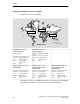
Preface Automation and Drives, Service & Support Available round the clock, worldwide: Nuremberg Johnson City Singapore SIMATIC Hotline Worldwide (Nuremberg) Worldwide (Nuremberg) Technical Support Technical Support (FreeContact) (fee-based, only with SIMATIC Card) Local time: Mon.-Fri. 8:00 to 17:00 Local time: Mon.-Fri. 0:00 to 24:00 Telephone: +49 (180) 5050-222 Telephone: +49 (911) 895-7777 Fax: +49 (180) 5050-223 Fax: +49 (911) 895-7001 E-Mail: techsupport@ ad.siemens.
Preface SIMATIC Customer Support Online Services The SIMATIC Customer Support team offers you substantial additional information about SIMATIC products via its online services: S General current information can be obtained – in the Internet unter http://www.siemens.com/simatic S Current Product Information leaflets, FAQs (Frequently Asked Questions), Downloads, Tips and Tricks can be obtained – in the Internet under http://www.siemens.
Preface x SIMATIC Panel PC 670 / 870 Operating Unit, Equipment Manual Edition 07/02
Table of Contents Table of Contents 1 2 3 4 Preface . . . . . . . . . . . . . . . . . . . . . . . . . . . . . . . . . . . . . . . . . . . . . . . . . . . . . . . . . . . . . . . . i Product Overview . . . . . . . . . . . . . . . . . . . . . . . . . . . . . . . . . . . . . . . . . . . . . . . . . . . . . . 1-1 1.1 Panel PC 670: Computing and operating units . . . . . . . . . . . . . . . . . . . . . . . 1-2 1.2 Panel PC 870: Computing and operating units . . . . . . . . . . . . . . . . . . . . .
Table of Contents 4.3 5 A B Replacing soft key labeling (operating units with key-based front panels only) . . . . . . . . . . . . . . . . . . . . 4-6 Remote Mount Form Factor . . . . . . . . . . . . . . . . . . . . . . . . . . . . . . . . . . . . . . . . . . . . . 5-1 5.1 5.1.1 5.1.2 Overview . . . . . . . . . . . . . . . . . . . . . . . . . . . . . . . . . . . . . . . . . . . . . . . . . . . . . . . Configuration . . . . . . . . . . . . . . . . . . . . . . . . . . . . . . . . . . . . . . . . . .
Product Overview Usage 1 The SIMATIC Panel PC 670/870 is an industry-standard PC platform for demanding tasks in the field of PC-based automation. The Panel PC is designed for on-site use on the machine, installed for example in S 19” cabinets/racks, S Control cabinets and consoles, S Swivel arms (booms).
Product Overview 1.1 Panel PC 670: Computing and operating units The computing unit is screwed to the rear of the operating unit with two mounting rails and can be separated from the latter. Figure 1-1 shows an example of the complete device and indicates the connection between the computing unit and the operating unit (2 of the 4 screw joints are marked with circles). Details on how to separate the two components are contained in Section 4.2.1. Computing unit Fig.
Product Overview S Membrane keyboard with alpha, numeric, cursor and control keypad S Function keys/soft keys – 2 x 8 vertical rows of keys with soft-key and optional direct–key functions – 2 x 10 horizontal rows of keys with soft-key functions – labeling strips for the rows of soft keys S Shift key for switching to the second level of key functions S Integrated piezo mouse S Status LEDs for power supply and temperature S USB interface on front side for connecting external peripheral devices S
Product Overview 1.2 Panel PC 870: Computing and operating units The computing unit is screwed to the rear of the operating unit with two mounting rails and can be separated from the latter (see Section 4.2.2). Figure 1-2 shows an example of the complete device: Operating unit Fig.
Product Overview S Function keys/soft keys – 2 x 8 vertical rows of keys with soft-key and optional direct-key functions – 2 x 10 horizontal rows of keys with soft-key functions – labeling strips for the rows of soft keys S Shift key for switching to the second level of key functions S Integrated piezo mouse S Status LEDs for power supply and temperature S USB interface on front side for connecting external peripheral devices S Degree of protection up to IP 65 1) depending on version S Mountin
Product Overview 1-6 SIMATIC Panel PC 670 / 870 Operating Unit, Equipment Manual Edition 07/02
2 Description of Device Table 2-1 indicates which combinations of operating units and computing units can be delivered.
Description of Device 2.1 Operating units with key-based front panels The number of keys, their labeling and their functionality are identical on all operating units featuring key-based front panels. The various types of front panel differ only in the arrangement the keys and the size and type of display. Figure 2-1 shows the front view of the 12” version as an example to illustrate the status indicators, the different keypads, the USB interface, display and mouse.
Description of Device 2.1.2 Keyboard The keyboard is subdivided into different functional groups of keys: S function keys, soft keys S control keys S alpha keys S numeric keys S cursor keys Function keys, soft keys The function keys arranged on the left and right of the display and in two rows at the bottom of the display possess LEDs and can be assigned freely. ... Fig.
Description of Device Alpha keys The alpha keys are used to enter letters, special characters, spaces and underscores: Underscore Space Fig. 2-4 Switching between upper-case and lower-case letters Alpha keys In their basic assignment, the alpha keys are used to enter lower-case letters. To enter upper-case letters, press and hold down SHIFT (see Figure 2-3). The LED on the SHIFT key lights and you can then enter upper-case letters with the corresponding alpha keys.
Description of Device Entering special characters, arithmetic characters and signs Most of the numeric keys have also been assigned special characters, arithmetic characters or the plus sign. The special characters are identified in white, in the top left corner of the keys concerned. To enter the plus sign, the special character or the arithmetic character you require, press the FN control key (see Figure 2-3) and, in addition, the appropriate numeric key.
Description of Device 2.2 Operating units with touchscreen front panels The 12.1” version and the 15.1” version of the touchscreen front panels differ in their dimensions and the size of their displays. The 12.1” version does not have drill holes (covers) at the sides. Figure 2-7 shows the 15.1” version as an example to illustrate the status indicators, the USB interface and the display.
Description of Device 2.3 Interfaces The operating unit has interfaces on the front and rear sides. 2.3.1 Front-side USB interface On the front side of the panel (see Figures 2-1 and 2-7) there is a USB interface *) protected by a rubber cover. This can be used, for example, to connect an external keyboard or an external mouse.
Description of Device 2.3.3 Interface assignment Front-side USB interface Table 2-2 Pin assignment of front-side USB interface Pin Name Type USB_GND V Chassis ground for external USB interface 3 USB_D0P B Data+, USB channel 0 2 USB_D0M B Data–, USB channel 0 1 USB_P5V_fused V + 5V (fused) for external USB interface; 4 3 2 Remark 4 max.
Description of Device 2.4 Device dimensions The following pages specify the unit dimensions for the Panel PC 670/870 in a central installation position.
Description of Device Dimensions of Panel PC 670 in standard mount form factor Computing unit in final position T2 ± 0.5 10 ± 0.5 T +3 10 Operating units Operating Unit A± 2 297 ± 0.5 Ü L ± 0.3 L H T T2 A B Ü (a) with key–based front panels: 10.4” TFT / 12.1” TFT 15.1” TFT 483 310 100 20 68 21 38 483 355 130 42 80 29 28 (b) with touchscreen front panels: 12.1” TFT 15.1” TFT 400 310 125 36 58 483 310 130 42 87 Fig. 2-9 H ± 0.5 Computing unit swung away by 90_ 267 ± 0.5 B± 1 2.4.
Description of Device Dimensions of Panel PC 870 in standard mount form factor Computing unit swung away by 90_ 2.4.2 150 ÏÏÏÏ ÏÏÏÏÏÏÏÏÏÏÏ ÏÏÏÏ ÏÏÏÏÏÏÏÏÏÏÏ ÏÏÏÏ ÏÏÏÏÏÏÏÏÏÏÏ ÏÏÏÏ ÏÏÏÏÏÏÏÏÏÏÏ ÏÏÏÏ ÏÏÏÏÏÏÏÏÏÏÏ Computing unit Computing unit swung away by 90_ Space for cables and ventilation Operating unit Operating units L H T T2 A B Ü (a) with key-based front panels: 12.1” TFT 15.1” TFT 483 310 187 20 50 12 143 483 355 212 42 50 20 143 (b) with touchscreen front panel: 15.
Description of Device 2-12 SIMATIC Panel PC 670 / 870 Operating Unit, Equipment Manual Edition 07/02
3 Mounting Note The Panel PC 670/870 is permitted for indoor use only. The display should not be exposed to direct sun light or other strong light sources. High frequency radiation, e.g. by mobile telephone equipment, may cause abnormal operational situations.
Mounting 3.1 Mounting cut-out 3.1.1 Panel PC 670 A mounting cut-out is required as shown in the figure below: 0.5 24 0.5 186 0.5 135 0.5 24 0.5 1) 5 1) H+1 W +1 Rz 120 D +1 H D 2) Operating units W (a) with key-based front panels: 10.” TFT / 12.1” TFT 15.1” TFT 450 290 100 450 321 130 min. 1.5 to max. 6 D 3) 69 91 1) cut–outs only for 15” TFT (keyboard version) 2) (b) with touchscreen front panels: 12.1” TFT 15.1” TFT Fig.
Mounting 3.1.2 Panel PC 870 A mounting cut-out is required as shown in the figure and explanatory table below: 5 0.5 24 0.5 186 0.5 135 0.5 24 0.5 1) *) H+1 W +1 Rz 120 D +1 H D 2) Operating units W (a) with key-based front panels: 10.” TFT / 12.1” TFT 15.1” TFT 450 290 100 450 321 130 D 3) 69 91 min. 1.5 to max. 6 1) cut–outs only for 15” TFT (keyboard version) 2) (b) with touchscreen front panels: 12.1” TFT 15.1” TFT Fig.
Mounting 3.2 Installation 3.2.1 Panel PC 670 The operating unit can be fitted in the mounting cut-out with either clamps or screws. Screwed joints are not possible with the 12.1” touchscreen version! Protection class IP 65 is possible when the operating unit is secured with clamps (in conjunction with a continuous gasket). Protection class IP 54 is achieved with screw fixings. Mounting location and dimensions The permissible mounting locations will depend on the attached computing unit.
Mounting Installation with clamp fixing The clamps and grub screws required for installation are supplied with the device. Proceed as follows: 1. Insert the complete operating unit and computing unit into the mounting cut-out prepared as described in Section 3.1, working from the front. 2. From the rear, fix the operating unit in position in the mounting cut-out using the six clamps (see Figure 3-3) by tightening the grub screws (torque 0.4 - 0.5 Nm). Installation with screw fixing The 12.
Mounting 3.2.2 Panel PC 870 The operating unit can be fitted in the mounting cut-out with either clamps or screws. S Protection class IP 65 is possible when the operating unit is secured with clamps (in conjunction with a continuous gasket). S Protection class IP 54 is achieved with screw fixings. A1 ±1 L3 ± 1 112 ± 0.5 112 ±0.5 56 ±1 Drill hole for screw fixings L2 +1 L5 ± 0.2 Pressure points for clamps Clamp with grub screws L3 ± 1 A2 ±1 112 ± 0.
Mounting Installation with clamp fixing The clamps and grub screws required for installation are supplied with the device. Proceed as follows: 1. Insert the complete operating unit and computing unit into the mounting cut-out prepared as described in Section 3.1, working from the front. 2. From the rear, fix the operating unit in position in the mounting cut-out using the six clamps (see Figure 3-3) by tightening the grub screws (torque 0.4 - 0.5 Nm). 3.
Mounting Installation with screw fixing Proceed as follows (Figure 3-6): Drill hole covers Fig. 3-6 Installation with screw fixing 1. Drill suitable holes around the prepared mounting cut-out (see Section 3.1) as specified for L4 and L5 in Figure 3-3. 2. Carefully knock out the drill hole covers on the front side of the opera- ting unit. 3. Fix the operating unit at the drill holes using suitable screws and nuts. 4. Continue as from step 3 for clamp fixing.
4 Maintenance 4.1 Spare parts and accessories 4.1.1 Spare parts The following are available as spare parts: S For the Panel PC in standard and remote mount form factor: the complete operating unit. It is not possible to quote a generally valid order number for the operating unit, since it depends on the current equipment configuration (operating unit plus computing unit) and its order number. You can obtain it from your Siemens office.
Maintenance 4.2 Detaching the operating unit in standard mount form factor from the computing unit It may at some stage become necessary to separate the operating unit from the computing unit, e.g. to replace the operating unit. 4.2.1 Panel PC 670 Swinging open the computing unit To swing the computing unit away from the operating unit, proceed as follows: 1. Undo the knurled screws which secure the computing unit to the rear side of the operating unit. 2.
Maintenance Removing the computing unit completely To remove the computing unit completely, continue as follows: 3. Remove the cable connectors K1 and K2 of the operating unit (see Fi- gure 4-2) from their corresponding counterparts on the computing unit. Two mounting rails are screwed to the computing unit. The two ends of these rails are formed as clips (see Figure 4-1). 4.
Maintenance 4.2.2 Panel PC 870 Removing the computing unit Proceed as follows: 1. Disconnect the power supply. 2. Swing open the mounting panel to obtain access to the rear of the PC 870. 3. Loosen the four (retained) knurled screws which secure the computing unit to the rear side of the operating unit (see also Figure 3–3). 4. Swing the computing unit away to the left, whereby the two left clips act as hinges and thus prevent an unintentional releasing of the computing unit.
Maintenance 1) 2) 1) 2) Display cable K2 3) I/O USB cable K1 3) 1) 3) 2) 1) Slits for mounting rails Cable folded: 200 mm longer than illustrated Fig. 4-4 1) 2) 2) Slits for soft-key labeling strips Rear side of operating panel with positions of interfaces Securing the computing unit Reinstall and swing the computing unit back into place in the reverse order to that described above (see also Section 3.2).
Maintenance 4.3 Replacing soft key labeling (operating units with key-based front panels only) The two horizontal and two vertical rows of soft keys of the operating units with key-based front panels can be assigned user-specific functions. You can use two printed labeling strips to identify the soft keys. A4 foil sheets are available for you to prepare the strips for insertion. Procedure: 1. Print the foil with a laser printer. 2. Cut the labeling strips along the preprinted lines. 3.
Remote Mount Form Factor 5 This chapter describes the specific features of the Panel PC in a remote mount form factor to the extent that they vary from the standard mount form factor (described in Chapters 2 to 4). The present document centers around the operating unit. The part of the description referring to the remote mount form factor of the computing unit will be found in ”Panel PC 670 Computing Unit” and ”Panel PC 870 Computing Unit” manuals.
Remote Mount Form Factor 5.1 Overview 5.1.1 Configuration Figure 5-1 shows the components in a remote mount form factor: 1. The receiver and (optionally) a direct key module are mounted on a mounting plate that is screwed to the rear panel of the operating unit, instead of the computing unit. 2. The transmitter is fitted between the mounting rails beneath the computing unit. 3. The receiver and transmitter are interconnected by a cable up to 20 m long (refer to Section 5.3).
Remote Mount Form Factor 1. PC 670/870 operating units with receiver: – 12” remote – 12” touch, remote *) – 15” remote – 15” touch, remote *) *) Includes operating units without USB port on front panel 2. Receiver power supplies: – 120 – 240 V AC – 24 V DC 3. Interconnecting cable: – 2m – 5m – 10 m – 20 m 4. Computing unit with transmitter: – Panel PC 670 remote – Panel PC 870 remote The order will be configured before leaving the works.
Remote Mount Form Factor 5.1.2 Block diagram The logical design of the remote mount form factor can be seen in Figure 5-2: S The transmitter is mounted on the computing unit. S The receiver is mounted on the operating unit. S The distance between the transmitter and the receiver (not more than 20 m) is bridged by the interconnecting cable. Computing unit Transmitter Max. 20m USB Operating unit Display LVDS Rec. Interconnecting cable LVDS Receiver ÀÀÀ ÀÀÀ ÀÀÀ Keyboard 12 V DC, 5 V DC, 3.
Remote Mount Form Factor 5.2 Description 5.2.1 Overview Figure 5-3 shows an example of the specific use of a 15” operating unit with mounted receiver and direct key module. The example shows the receiver with the 120 to 240 V AC power supply. The receiver can alternatively be ordered with the 24 V DC power supply. Socket for interconnecting cable to transmitter Power supply 120–240 V AC Fig.
Remote Mount Form Factor 5.2.2 Dimensions The dimensions of the mounting plate for the receiver and direct key module can be seen in Figure 5-4. The included table contains the dimensions depending on the chosen operating unit. D 48,6 ±0,5 A ±0,5 Receiver Direct key module (optional) Power supply Operating unit 319 80 B ±1 269 C±1 E ±2 295 Dimen– sion A 15” 12” 12” Touch 15” Touch 483 400 483 483 B 310 C 21 Fig. 5-4 5-6 310 23 354 310 29 23 Dim.
Remote Mount Form Factor 5.2.3 Mounting The operating unit is supplied as a complete combination: operating unit with mounting plate, on which the receiver is mounted, on the rear panel. The procedure for installation in a cabinet or housing is the same as that described in Chapter 3. The mounting depth has to be taken into account (refer to Figure 5-4). It results from D + 48,6 mm + 10 mm (10 mm additional space for ventilation).
Remote Mount Form Factor 5.3 Cable connection The transmitter (refer to ”Computing Unit” manual) and receiver are interconnected by a cable not longer than 20 m (example shown in Figure 5-5). Male connector for connecting to computing unit Female connector for connecting to operating unit Fig.
A Appendix A: Technical Data A.1 Technical data of operating unit standard mount form factor Table A-1 Panel PC technical data Color display 1) 10.4” TFT 12.1” TFT 15.1” TFT Resolution 640 x 480 800 x 600 1024 x 768 MTBF of back-lighting Keyboard and mouse 15.1 “ TFT Touchscreen 1024 x 768 Typically 60,000 (24 h continuous operation, temperature-dependent) — n n 36 with LEDs — — Touchscreen, analog resistive Membrane keyboard with alpha/numeric block Function keys 12.
Appendix A: Technical Data Interfaces USB standard mount form factor USB remote mount form factor 1 x front panel 1) 1 x front panel 1), 1 x rear panel Safety Protection class Degree of protection Safety regulations Electromagnetic compatibility Certification Power supply Oscillation load in operation tested to Shock load in operation tested to Conforms to VDE 0106 T1: 1982 (IEC 536) a.
Appendix A: Technical Data A.2 Technical specifications for Panel PC operating unit with remote mount form factor This section describes the technical specifications that differ from those of the standard mount form factor. Table A-2 Properties of the operating unit with receiver Electrical data Power input AC power supply DC power supply Max. 0.67 A (120 V) / max. 0.48 A (240 V) Max. 1.7 A (24 V) Max. approx. 70 VA Max. approx. 41 W Power input IEC corresponding to DIN VDE 0805/11.
Appendix A: Technical Data A.4 Keyboard table (operating units with key-based front panels) By using the following table, you can check the standard keyboard assignment and the corresponding key codes.
Appendix A: Technical Data Key number Code Key label/name 20 14 q 20a1 33/AS ° 21 13 p 21a1 31/s ’ 22 12 o 22a1 31 \ 23 11 n 23a1 30/s } 24 10 m 24a1 2f/s { 25 40 F7 26 3e/s F17 (Shift F5) 27 26 9 27a1 22/s % 28 25 8 28a1 22/A 29 24 7 29a1 21/s $ 30 18 u 30a1 33/s : 31 17 t 31a1 33 ; 32 16 s 32a1 36 , 33 3f F6 34 3d/s F16 (Shift F4) 35 23 6 35a1 23/s ^ 36 22 5 36a1 37/s > 37 21 4 37a1 36/s < 38 1b x 39 1a
Appendix A: Technical Data A-6 Key number Code Key label/name 43 20 3 43a1 38 / 44 1f 2 44a1 25/s * 45 1e 1 46 2c (BLANK) 46a1 2d/s _ 47 1d z 48 1c y 48a1 1f/s @ 49 3d F4 50 3b/s F14 (Shift F2) 51 56 - 51a1 57 + 52 27 0 52a1 2e = 53 37 .
Appendix A: Technical Data Key number Code Key label/name 80 2b (TAB) 80A1 2b/s (SHIFT TAB) 81 00/c (CONTROL) 82 00/s (SHIFT) 82A1 39 (CAPS LOCK) 83 00/a (ALT) 89 42/s,1 S1 (Shift F9) 90 43/s,2 S2 (Shift F10) 91 44/s,3 S3 (Shift F11) 92 45/s,4 S4 (Shift F12) 93 3a/c,5 S5 (control F1) 94 3b/c,6 S6 (control F2) 95 3c/c,7 S7 (control F3) 96 3d/c,8 S8 (control F4) 97 3e/c,9 S9 (control F5) 98 3f/c,10 S10 (control F6) 99 40/c,11 S11 (control F7) 100 41/c,12
Appendix A: Technical Data A-8 SIMATIC Panel PC 670 / 870 Operating Unit, Equipment Manual Edition 07/02
Appendix B: ESD Guidelines B What does ESD mean? Virtually all present-day modules incorporate highly integrated MOS devices or components. Due to the technologies used, these electronic components are very sensitive to overvoltages and consequently therefore to electrostatic discharge: These devices are referred to in German as Elektrostatisch Gefährdeten Bauelemente/Baugruppen: EGB. The more frequent international designation is: ESD (Electrostatic Sensitive Device).
Appendix B: ESD Guidelines Handling ESD assemblies A general rule is that assemblies should be touched only when this cannot be avoided in the course of the work that has to performed on them. Under no circumstances should you touch device pins or circuitry when handling printed-circuit boards. You should touch devices only if S you are grounded by permanently wearing an ESD wrist strap or S you are wearing ESD shoes or ESD shoe-grounding protection straps in conjunction with an ESD floor.
Index Index Numbers G 15” control unit, 5-5 grub screws, 3-5, 3-7 guidelines, ESD, B-1 A alpha keys, 2-4 ambient conditions, A-2 approvals, A-3 arithmetic characters, 2-5 H heat dissipation, A-2 I C cabinet installation, 5-7 cable, 5-2 cable connectors, 4-3, 4-4 certification, A-2 clamps, 1-3, 1-5, 3-5, 3-7 control keys, 2-3 cursor keys, 2-5 D degree of protection, 1-3, 1-5 device front panel key–based panels, 2-2 touchscreen panels, 2-6 direct key module, 5-2, 5-5, 5-6 discharges electrostatic, B-1
Index O S operating unit, installation, 3-4 overvoltage, B-1 safety, A-2, A-3 safety regulations, A-2 SHIFT key, 1-3, 1-5 shock load, A-2 signs, 2-5 soft keys, 1-3, 1-5, 2-3 special characters, 2-4, 2-5 static discharges, B-1 status LEDs, 1-3, 1-5 P Panel PC alpha keys, 2-4 control keys, 2-3 cursor keys, 2-5 function keys, 2-3 numeric keys, 2-4 soft keys, 2-3 Panel PC 670: computing and operating units, 1-2 Panel PC 870: computing and operating units, 1-4 peripheral devices, 2-7 power input, A-3 power