Preface, Contents General Technical Specifications Racks SIMATIC S7-400, M7-400 Programmable Controllers Module Specifications Reference Manual Power Supply Modules Digital Modules Analog Modules Interface Modules IM 463-2 PROFIBUS DP Master Interface IM 467/IM 467 FO Cable Duct and Fan Subassemblies RS 485 Repeater CPUs for M7-400 M7-400 Expansions Interface Submodules Appendices Parameter Sets for Signal Modules Diagnostic Data of the Signal Modules This manual is part of the documentation package with
Safety Guidelines This manual contains notices intended to ensure personal safety, as well as to protect the products and connected equipment against damage. These notices are highlighted by the symbols shown below and graded according to severity by the following texts: ! ! ! Danger indicates that death, severe personal injury or substantial property damage will result if proper precautions are not taken.
Preface Purpose of the Manual The manual contains reference information on operator actions, descriptions of functions and technical specifications of the central processing units, power supply modules and interface modules of the S7-400. How to configure, assemble and wire these modules in an S7-400 or M7-400 system is described in the installation manuals for each system. Required Basic Knowledge You will need a general knowledge of automation to understand this manual.
Preface Changes Compared to the Previous Version Since the previous version of the “Module Specifications” reference manual, the following changes have been made: • The descriptions of the CPU and the CPU relevant products and topics have been put together in one manual, “CPU Specifications”.
Preface System S7-400/M7-400 Documentation Package • S7-400, M7-400 Programmable Controllers; Hardware and Installation • S7-400, M7-400 Programmable Controllers; Module Specifications • Automation System S7-400 CPU Data • S7-400 Instruction List Finding Your Way To help you find special information quickly, the manual contains the following access aids: • At the start of the manual you will find a complete table of contents and a list of the diagrams and tables that appear in the manual.
Preface Specific Information for S7-400 You require the following manuals and manual packages in order to program and commission an S7-400: Manual/ Manual Package Standard Software for S7 and M7 Contents • Installing and starting up STEP 7 on a programming device / PC • Working with STEP 7 with the following contents: STEP 7 Basic Information Managing projects and files Configuring and assigning parameters to the S7-400 configuration Assigning symbolic names for user programs Creating and testing a us
Preface Specific Information for M7-400 This documentation package describes the hardware of the M7-400.
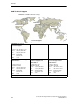
Preface A&D Technical Support Worldwide, available 24 hours a day: Nuernberg Johnson City Beijing Technical Support Worldwide (Nuernberg) Technical Support 24 hours a day, 365 days a year Phone: +49 (180) 5050-222 Fax: +49 (180) 5050-223 E-Mail: adsupport@ siemens.com GMT: +1:00 Europe / Africa (Nuernberg) United States (Johnson City) Asia / Australia (Beijing) Authorization Technical Support and Authorization Technical Support and Authorization Local time: Mon.-Fri.
Preface Service & Support on the Internet In addition to our documentation, we offer our Know-how online on the internet at: http://www.siemens.com/automation/service&support where you will find the following: • The newsletter, which constantly provides you with up–to–date information on your products. • The right documents via our Search function in Service & Support. • A forum, where users and experts from all over the world exchange their experiences.
Preface x S7-400, M7-400 Programmable Controllers Module Specifications A5E00069467-07
Contents 1 General Technical Specifications . . . . . . . . . . . . . . . . . . . . . . . . . . . . . . . . . . . . . . . . . 1-1 1.1 Standards and Approvals . . . . . . . . . . . . . . . . . . . . . . . . . . . . . . . . . . . . . . . . . 1-2 1.2 Electromagnetic Compatibility . . . . . . . . . . . . . . . . . . . . . . . . . . . . . . . . . . . . . 1-9 1.3 Shipping and Storage Conditions for Modules and Backup Batteries . . . . 1-12 1.
Contents 4 3.12 Power Supply Module PS 405 4A; (6ES7405-0DA01-0AA0) . . . . . . . . . . . 3-32 3.13 Power Supply Module PS 405 10A; (6ES7405-0KA00-0AA0) . . . . . . . . . . 3-34 3.14 Power Supply Modules PS 405 10A; (6ES7405-0KA01-0AA0) and PS 405 10A R; (405-0KR00-0AA0) . . . . . . . . . . . . . . . . . . . . . . . . . . . . . . . . . 3-36 3.15 Power Supply Module PS 405 20A; (6ES7405-0RA00-0AA0) . . . . . . . . . . 3-38 3.16 Power Supply Module PS 405 20A; (6ES7405-0RA01-0AA0) . . . . . . .
Contents 4.17 Digital Output Module SM 422; DO 16 24 VDC/2 A; (6ES7422-1BH11-0AA0) . . . . . . . . . . . . . . . . . . . . . 4-62 Digital Output Module SM 422; DO 16 0-125 VDC/1.5 A; (6ES7422-5EH10-0AB0) . . . . . . . . . . . . . . . . . . . . . . . . . . . . . . . . . . . . . . . . . . Assigning Parameters to the SM 422; DO 16 20-125 VDC/1.5 A . . . . 4-65 4-69 Digital Output Module SM 422; DO 32 24 VDC/0.5 A; (6ES7422-1BL00-0AA0) . . . . . . . . . . . . . . . . . . . . . . . . . . . . . . . . . . .
Contents 5.13 Connecting Loads/Actuators to Analog Outputs . . . . . . . . . . . . . . . . . . . . . . 5-58 5.14 Connecting Loads/Actuators to Voltage Outputs . . . . . . . . . . . . . . . . . . . . . . 5-59 5.15 Connecting Loads/Actuators to Current Outputs . . . . . . . . . . . . . . . . . . . . . . 5-61 5.16 Diagnostics of the Analog Modules . . . . . . . . . . . . . . . . . . . . . . . . . . . . . . . . . 5-62 5.17 Analog Module Interrupts . . . . . . . . . . . . . . . . . . . . . . . . .
Contents 6 Interface Modules . . . . . . . . . . . . . . . . . . . . . . . . . . . . . . . . . . . . . . . . . . . . . . . . . . . . . . . 6-1 6.1 Common Features of the Interface Modules . . . . . . . . . . . . . . . . . . . . . . . . . 6-2 6.2 The Interface Modules IM 460-0; (6ES7460-0AA00-0AB0, 6ES7460-0AA01-0AB0) and IM 461-0; (6ES7461-0AA00-0AA0, 6ES7461-0AA01-0AA0) . . . . . . .
Contents 10 11 12 xvi RS 485 Repeater . . . . . . . . . . . . . . . . . . . . . . . . . . . . . . . . . . . . . . . . . . . . . . . . . . . . . . . . . 10-1 10.1 Application and Characteristics (6ES7972-0AA01-0XA0) . . . . . . . . . . . . . . 10-2 10.2 Appearance of the RS 485 Repeater; (6ES7972-0AA01-0XA0) . . . . . . . . 10-3 10.3 RS 485 Repeater in Ungrounded and Grounded Operation . . . . . . . . . . . . 10-4 10.4 Technical Specifications . . . . . . . . . . . . . . . . . . . . . . . .
Contents 13 Interface Submodules . . . . . . . . . . . . . . . . . . . . . . . . . . . . . . . . . . . . . . . . . . . . . . . . . . . 13-1 13.1 Interface Submodules Overview . . . . . . . . . . . . . . . . . . . . . . . . . . . . . . . . . . . 13-2 13.2 Submodule IDs and Insertion Rules . . . . . . . . . . . . . . . . . . . . . . . . . . . . . . . . 13-4 13.3 IF 962-VGA Interface Submodule for M7-300/400; (6ES7962-1BA00-0AC0) . . . . . . . . . . . . . . . . . . . . . . . . . . . . . . . . . . .
Contents 13.9 13.9.1 13.9.2 13.9.3 A B IF 964-DP Interface Submodule for S7-400 and M7-400 . . . . . . . . . . . . . . Pin Assignments . . . . . . . . . . . . . . . . . . . . . . . . . . . . . . . . . . . . . . . . . . . . . . . . . Addressing and Interrupts . . . . . . . . . . . . . . . . . . . . . . . . . . . . . . . . . . . . . . . . . Technical Specifications . . . . . . . . . . . . . . . . . . . . . . . . . . . . . . . . . . . . . . . . . . .
Contents Figures 1-1 2-1 2-2 2-3 2-4 2-5 2-6 3-1 3-2 3-3 3-4 3-5 3-6 3-7 3-8 3-9 3-10 3-11 3-12 4-1 4-2 4-3 4-4 4-5 4-6 4-7 4-8 4-9 4-10 4-11 4-12 4-13 4-14 4-15 4-16 4-17 4-18 Power supply to the backup battery . . . . . . . . . . . . . . . . . . . . . . . . . . . . . . . . . Structure of a Rack with 18 Slots . . . . . . . . . . . . . . . . . . . . . . . . . . . . . . . . . . . Dimensions of the UR1 18-Slot or UR2 9-Slot Rack . . . . . . . . . . . . . . . . . . Rack Dimensions . . . . . . . . . . . . .
Contents 4-19 4-20 4-21 4-22 5-1 5-2 5-3 5-4 5-5 5-6 5-7 5-8 5-9 5-10 5-11 5-12 5-13 5-14 5-15 5-16 5-17 5-18 5-19 5-20 5-21 5-22 5-23 5-24 5-25 5-26 5-27 5-28 5-29 5-30 5-31 5-32 5-33 5-34 5-35 5-36 5-37 xx Terminal Assignment and Block Diagram of the SM 422; DO 8 x 120/230 VAC/5 A . . . . . . . . . . . . . . . . . . . . . . . . . . . . . . . . . . . . . . . . . . Terminal Assignment and Block Diagram of the SM 422; DO 16 x 120/230 VAC/2 A . . . . . . . . . . . . . . . . . . . . . . . . . . . . . . . .
Contents 5-38 5-39 5-40 5-41 5-42 5-43 5-44 5-45 5-46 5-47 5-48 6-1 6-2 6-3 6-4 6-5 7-1 7-2 7-3 8-1 8-2 8-3 8-4 8-5 8-6 8-7 9-1 9-2 9-3 9-4 10-1 10-2 10-3 11-1 11-2 11-3 11-4 11-5 Block Diagram of the SM 431; AI 8 x RTD x 16 Bit . . . . . . . . . . . . . . . . . . . . Terminal Assignment Diagram of the SM 431; AI 8 x RTD x 16 Bit . . . . . . Step Response of the SM 431; AI 8 x RTD x 16 Bit . . . . . . . . . . . . . . . . . . . Block Diagram of the SM 431; AI 8 x 16 Bit . . . . . . . . . . . . . . . . . .
Contents 11-6 11-7 11-8 11-9 11-10 11-11 11-12 11-13 11-14 11-15 11-16 11-17 11-18 11-19 12-1 12-2 12-3 12-4 12-5 12-6 12-7 12-8 12-9 12-10 13-1 13-2 13-3 13-4 13-5 13-6 13-7 13-8 13-9 13-10 13-11 13-12 13-13 13-14 13-15 13-16 13-17 13-18 13-19 xxii POST Window for a CPU 488-3 . . . . . . . . . . . . . . . . . . . . . . . . . . . . . . . . . . . . Warm Restart Window for a CPU . . . . . . . . . . . . . . . . . . . . . . . . . . . . . . . . . . Context-Sensitive Help Window . . . . . . . . . . . . . . . .
Contents 13-20 13-21 13-22 13-23 13-24 13-25 A-1 A-2 A-3 A-4 A-5 B-1 B-2 B-3 B-4 B-5 B-6 B-7 B-8 B-9 B-10 B-11 B-12 B-13 B-14 B-15 B-16 B-17 B-18 B-19 B-20 B-21 B-22 B-23 B-24 B-25 B-26 B-27 D-1 Connecting Loads/Actuators via a Two-Wire Connection to a Current Output . . . . . . . . . . . . . . . . . . . . . . . . . . . . . . . . . . . . . . . . . . . . . . . Connecting Loads/Actuators via a Three-Wire Connection to a Voltage Output . . . . . . . . . . . . . . . . . . . . . . . . . . . . . . . . . . . . .
Contents Tables 1-1 1-2 1-3 1-4 1-5 1-6 1-7 1-8 1-9 1-10 1-11 1-12 1-13 1-14 1-15 1-16 3-1 3-2 3-3 3-4 3-5 3-6 3-7 3-8 3-9 3-10 3-11 4-1 4-2 4-3 4-4 4-5 4-6 4-7 4-8 4-9 4-10 4-11 4-12 4-13 4-14 4-15 4-16 xxiv Use in an Industrial Environment . . . . . . . . . . . . . . . . . . . . . . . . . . . . . . . . . . Products that Fulfill the Requirements of the Low-Voltage Directive . . . . Power Supply Modules . . . . . . . . . . . . . . . . . . . . . . . . . . . . . . . . . . . . . . . . . . .
Contents 4-17 4-18 4-19 4-20 5-1 5-2 5-3 5-4 5-5 5-6 5-7 5-8 5-9 5-10 5-11 5-12 5-13 5-14 5-15 5-16 5-17 5-18 5-19 5-20 5-21 5-22 5-23 5-24 5-25 5-26 5-27 5-28 5-29 5-30 5-31 5-32 5-33 5-34 5-35 5-36 Parameters of the SM 422; DO 16 20-125 VDC/1.5 A . . . . . . . . . . . . . . Parameters of the SM 422; DO 32 24 VDC/0.5 A (6ES7422-7BL00-0AB0) . . . . . . . . . . . . . . . . . . . . . . . . . . . . . . . . . . . . . . . . . .
Contents 5-37 5-38 5-39 5-40 5-41 5-42 5-43 5-44 5-45 5-46 5-47 5-48 5-49 5-50 5-51 5-52 5-53 5-54 5-55 5-56 5-57 5-58 5-59 5-60 5-61 5-62 5-63 5-64 5-65 5-66 5-67 5-68 5-69 5-70 5-71 5-72 5-73 xxvi Analog Value Representation in Output Ranges 0 and 20 mA and 4 to 20 mA . . . . . . . . . . . . . . . . . . . . . . . . . . . . . . . . . . . . . . . . . . . . . . . . . . Dependencies of the Analog Input/Output Values on the Operating Mode of the CPU and the Supply Voltage L+ . . . . . . . .
Contents 5-74 5-75 5-76 5-77 5-78 6-1 6-2 6-3 7-1 7-2 7-3 7-4 7-5 7-6 7-7 8-1 8-2 9-1 10-1 10-2 10-3 11-1 11-2 11-3 11-4 11-5 11-6 11-7 11-8 11-9 12-1 12-2 12-3 12-4 12-5 12-6 12-7 13-1 13-2 13-3 13-4 13-5 13-6 13-7 Parameters of the SM 431; AI 8 x 16 Bit . . . . . . . . . . . . . . . . . . . . . . . . . . . . How Response Times Depend on the Parameterized Interference Frequency Suppression and Smoothing of the SM 431; AI 8 x 16 Bit . . . . . . . . . . . . . . . . . . . . . . . . .
Contents 13-8 13-9 13-10 13-11 13-12 13-13 13-14 13-15 13-16 13-17 13-18 13-19 13-20 13-21 13-22 13-23 13-24 13-25 13-26 13-27 13-28 13-29 13-30 13-31 13-32 13-33 13-34 13-35 13-36 13-37 13-38 13-39 13-40 13-41 13-42 13-43 13-44 13-45 A-1 A-2 A-3 A-4 B-1 xxviii Socket X1, X2 IF 962-COM (9-Pin Sub D Plug Connector) . . . . . . . . . . . . Addressing the COM Ports in the AT-Compatible Address Area . . . . . . . . Offset Address Assignments for the IF 962-COM Interface Submodule . .
General Technical Specifications 1 What are General Technical Specifications? General technical specifications include the following: • The standards and test specifications complied with and met by the modules of the S7-400/M7-400 programmable controllers • The test criteria against which the S7-400/M7-400 modules were tested Chapter Overview Section Description Page 1.1 Standards and Approvals 1-2 1.2 Electromagnetic Compatibility 1-9 1.
General Technical Specifications 1.1 Standards and Approvals Note You will find the current approvals on the identification label of the respective products. IEC 61131-2 The S7-400/M7-400 programmable controller satisfies the requirements and criteria of the IEC 61131-2 standard (programmable controllers, part 2 on equipment requirements and tests).
General Technical Specifications Low Voltage Directive The products listed in the table below fulfill the requirements of EU low-voltage directive (73/23/EEC). Adherence to this EU directive was tested in accordance with IEC 61131-2.
General Technical Specifications Mark for Australia and New Zealand Our products satisfy the requirements of Standard AS/NZS 2064 (Class A). Note You will recognize the approval assigned to your product from the mark on the identification label. The opprovals are listed below UL/CSA or cULus.
General Technical Specifications or cULus Approval, Hazardous Location CULUS Listed 7RA9 INT. CONT. EQ. FOR HAZ. LOC. Underwriters Laboratories Inc. nach HAZ. LOC. UL 508 (Industrial Control Equipment) CSA C22.2 No. 142 (Pocess Control Equipment) UL 1604 (Hazardous Location) CSA-213 (Hazardous Location) APPROVED for Use in Cl. 1, Div. 2, GP. A, B, C, D T4A Cl. 1, Zone 2, GP. IIC T4 Please read the notes below.
General Technical Specifications cuULu requirements on hazardous location on the battery power supply for CPUs The power supply to the backup battery of a CPU must be via a non–incendive plug. The figure below portrays the concept of such connection. CPU with connector “ext. batt.
General Technical Specifications Battery/Power supply CPU iput “Ext. Batt.” incl. cable Ca ≥ Ci + Cc (25nF + Cc) La ≥ Li + Lc (2mH + Lc) The batteries used must have the following properties: • Battery technology: Li/SOCL2 • Model: AA • Voltage: 3.6 V The batteries stipulated by Siemens fulfil requirements that go beyond the ones mentioned above.
General Technical Specifications FM Approval Factory Mutual Approval Standard Class Number 3611, Class I, Division 2, Group A, B, C, D.
General Technical Specifications Safety Requirements for Installation The S7-400/M7-400 programmable controllers are “open type” equipment to the IEC 61131-2 standard and therefore adhere to the EU directive 73/23/EEC “Low-Voltage Directive” and are UL/CSA certified as such.
General Technical Specifications Pulse-Shaped Interference The following table shows the electromagnetic compatibility of modules when there are pulse-shaped disturbance variables. A requirement for this is that the S7-400/M7-400 system complies with the relevant requirements and guidelines on electric design.
General Technical Specifications Emission of Radio Interference Interference emission of electromagnetic fields in accordance with EN 55011: Limit value class A, Group 1. Table 1-6 Interference emission of electromagnet fields Frequency Range Limit Value From 20 to 230 MHz 30 dB ( V/m)Q From 230 to 1000 MHz 37 dB ( V/m)Q Measured at a distance of 30 m (98.4 ft.) Emitted interference via the mains AC power supply in accordance with EN 55011: Limit value class A, group 1.
General Technical Specifications Additional Measures If you want to connect an S7-400 or M7-400 system to the public power system, you must ensure compliance with limit value class B in accordance with EN 55022. Suitable additional measures must be taken, if you need to enhance the noise immunity of the system as a result of high external noise levels. 1.
General Technical Specifications Storing Backup Batteries Backup batteries must be stored in a cool, dry place. The maximum storage time is 10 years. ! Warning Improper handling of backup batteries can cause injury and material damage. If backup batteries are not treated properly, they can explode and cause severe burning.
General Technical Specifications 1.4 Mechanical and Ambient Climatic Conditions for Operating the S7-400/M7-400 Operating Conditions The S7-400/M7-400 is designed for weather-protected use as a permanent installation.
General Technical Specifications Table 1-11 Ambient Mechanical Conditions for the MSM 478 Mass Storage Module in Operation Frequency Range in Hz Test Values 10 ≤ f < 58 58 ≤ f < 500 0.035 mm amplitude 0.5 g constant acceleration Shock Semi-sinusoidal 5 g, 11 ms Reducing Vibrations If the S7-400/M7-400 is subject to high levels of shock or vibration, you must take suitable measures to reduce the acceleration or amplitude.
General Technical Specifications Table 1-13 Ambient Climatic Conditions for the S7-400 Climatic Conditions Permitted Range Remark Relative humidity Max.
General Technical Specifications Ambient Climatic Conditions for the M7-400 The M7-400 may be used under the following ambient climatic conditions: Table 1-15 Ambient Climatic Conditions for the M7-400 Climatic Conditions Temperature Permitted Range Remark 0 to +60 °C When using a CPU 486-3 or 488-3 5 to +55 °C When using an MSM 478 without diskette operation but with ventilation 5 to +40 °C When using an MSM 478 with diskette operation or without ventilation (when using an ATM 478, the permissible
General Technical Specifications 1.
General Technical Specifications 1.6 Using S7-400 in a zone 2 explosion–risk area You will find important information in different languages in the chapters below. Chapter overview Chapter Thema 1.6.1 Einsatz der S7-400 im explosionsgefährdeten Bereich Zone 2 1.6.2 Use of the S7-400 in a Zone 2 Hazardous Area 1.6.3 Utilisation de la S7-400 dans un environnement à risque d’explosion en zone 2 1.6.4 Aplicación del S7-400 en áreas con peligro de explosión, zona 2 1.6.
General Technical Specifications 1.6.1 Einsatz der S7-400 im explosionsgefährdeten Bereich Zone 2 Zone 2 Explosionsgefährdete Bereiche werden in Zonen eingeteilt. Die Zonen werden nach der Wahrscheinlichkeit des Vorhandenseins einer explosionsfähigen Atmosphäre unterschieden.
General Technical Specifications Instandhaltung Für eine Reparatur muss die betroffene Baugruppe an den Fertigungsort geschickt werden. Nur dort darf die Reparatur durchgeführt werden. Besondere Bedingungen 1. Die SIMATIC S7-400 muss in einen Schaltschrank oder ein metallisches Gehäuse eingebaut werden. Diese müssen mindestens die Schutzart IP 54 (nach EN 60529) gewährleisten. Dabei sind die Umgebungsbedingungen zu berücksichtigen, in denen das Gerät installiert wird.
General Technical Specifications 1.6.2 Use of the S7-400 in a Zone 2 Hazardous Area Zone 2 Hazardous areas are divided up into zones. The zones are distinguished according to the probability of the existence of an explosive atmosphere.
General Technical Specifications Maintenance If repair is necessary, the affected module must be sent to the production location. Repairs can only be carried out there. Special Conditions 1. The SIMATIC S7-400 must be installed in a cabinet or metal housing. These must comply with the IP 54 (in accordance with EN 60529) degree of protection as a minimum. The environmental conditions under which the equipment is installed must be taken into account.
General Technical Specifications 1.6.3 Utilisation du S7-400 dans un environnement à risque d'explosion en zone 2 Zone 2 Les environnements à risque d'explosion sont répartis en zones. Les zones se distinguent par la probabilité de présence d'une atmosphère explosive.
General Technical Specifications Entretien Si une réparation est nécessaire, le module concerné doit être expédié au lieu de production. La réparation ne doit être effectuée qu'en ce lieu. Conditions particulières 1. Le SIMATIC S7-400 doit être installé dans une armoire ou un boîtier métallique. Ceux-ci doivent assurer au moins l'indice de protection IP 54. Il faut alors tenir compte des conditions d'environnement dans lesquelles l'appareil est installé.
General Technical Specifications 1.6.4 Aplicación de la S7-400 en áreas con peligro de explosión, zona 2 Zona 2 Las áreas con peligro de explosión se clasifican en zonas. Las zonas se diferencian según la probabilidad de la existencia de una atmósfera capaz de sufrir una explosión.
General Technical Specifications Mantenimiento Para una reparación se ha de remitir el módulo afectado al lugar de fabricación. Sólo allí se puede realizar la reparación. Condiciones especiales 1. El SIMATIC S7-400 se ha de montar en un armario eléctrico de distribución o en una carcasa metálica. Éstos deben garantizar como mínimo el grado de protección IP 54 (conforme a EN 60529). Para ello se han de tener en cuenta las condiciones ambientales, en las cuales se instala el equipo.
General Technical Specifications 1.6.5 Impiego dell'S7-400 nell'area a pericolo di esplosione zona 2 Zona 2 Le aree a pericolo di esplosione vengono suddivise in zone. Le zone vengono distinte secondo la probabilità della presenza di un'atmosfera esplosiva.
General Technical Specifications Manutenzione Per una riparazione, l'unità interessata deve essere inviata al luogo di produzione. La riparazione può essere effettuata solo lì. Condizioni particolari 1. Il SIMATIC S7-400 deve essere montato in un armadio elettrico o in un contenitore metallico. Questi devono assicurare almeno il tipo di protezione IP 54 (secondo EN 60529). In questo caso bisogna tenere conto delle condizioni ambientali nelle quali l'apparecchiatura viene installata.
General Technical Specifications 1.6.6 Gebruik van de S7-400 in het explosief gebied zone 2 Zone 2 Explosieve gebieden worden ingedeeld in zones. Bij de zones wordt onderscheiden volgens de waarschijnlijkheid van de aanwezigheid van een explosieve atmosfeer.
General Technical Specifications Instandhouding Voor een reparatie moet de betreffende module naar de plaats van vervaardiging worden gestuurd. Alleen daar mag de reparatie worden uitgevoerd. Speciale voorwaarden 1. Het SIMATIC S7-400 moet worden ingebouwd in een schakelkast of in een behuizing van metaal. Deze moeten minstens de veiligheidsgraad IP 54 (volgens EN 60529) waarborgen. Hierbij dient rekening te worden gehouden met de omgevingsvoorwaarden waarin het apparaat wordt geïnstalleerd.
General Technical Specifications 1.6.7 Brug af S7-400 i det eksplosionfarlige område zone 2 Zone 2 Eksplosionsfarlige områder inddeles i zoner. Zonerne adskiller sig indbyrdes efter hvor sandsynligt det er, at der er en eksplosiv atmosfære.
General Technical Specifications Vedligeholdelse Skal den pågældende komponent repareres, bedes De sende den til produktionsstedet. Reparation må kun udføres der. Særlige betingelser 1. SIMATIC S7-400 skal monteres i et kontrolskab eller et metalkabinet. Disse skal mindst kunne sikre beskyttelsesklasse IP 54. I denne forbindelse skal der tages højde for de omgivelsestemperaturer, i hvilke udstyret er installeret. Der skal være udarbejdet en erklæring fra fabrikanten for kabinettet for zone 2 (iht.
General Technical Specifications 1.6.8 S7-400:n käyttö räjähdysvaarannetuilla alueilla, vyöhyke 2 Vyöhyke 2 Räjähdysvaarannetut alueet jaetaan vyöhykkeisiin. Vyöhykkeet erotellaan räjähdyskelpoisen ilmakehän olemassa olon todennäköisyyden mukaan.
General Technical Specifications Kunnossapito Korjausta varten täytyy kyseinen rakenneryhmä lähettää valmistuspaikkaan. Korjaus voidaan suorittaa ainoastaan siellä. Erityiset vaatimukset 1. SIMATIC S7-400 täytyy asentaa kytkentäkaappiin tai metalliseen koteloon. Näiden täytyy olla vähintään kotelointiluokan IP 54 mukaisia. Tällöin on huomioitava ympäristöolosuhteet, johon laite asennetaan. Kotelolle täytyy olla valmistajaselvitys vyöhykettä 2 varten (EN 50021 mukaan). 2.
General Technical Specifications 1.6.9 Användning av S7-400 i explosionsriskområde zon 2 Zon 2 Explosionsriskområden delas in i zoner. Zonerna delas in enligt sannolikheten att en atmosfär med explosionsfara föreligger.
General Technical Specifications Underhåll Vid reparation måste den aktuella komponentgruppen insändas till tillverkaren. Reparationer får endast genomföras där. Särskilda villkor 1. SIMATIC S7-400 måste monteras i ett kopplingsskåp eller metallhus. Dessa måste minst vara av skyddsklass IP 54. Därvid ska omgivningsvillkoren där enheten installeras beaktas. För kåpan måste en tillverkardeklaration för zon 2 föreligga (enligt EN 50021). 2.
General Technical Specifications 1.6.10 Uso do S7-400 em área exposta ao perigo de explosão 2 Zona 2 As áreas expostas ao perigo de explosão são divididas em zonas. As zonas são diferenciadas de acordo com a probabilidade da existência de uma atmosfera explosiva.
General Technical Specifications Reparo Os componente em questão deve ser remetido para o local de produção a fim de que seja realizado o reparo. Apenas lá deve ser efetuado o reparo. Condições especiais 1. O SIMATIC S7-400 deve ser montado em um armário de distribuição ou em uma caixa metálica. Estes devem garantir no mínimo o tipo de proteção IP 54. Durante este trabalho deverão ser levadas em consideração as condições locais, nas quais o aparelho será instalado.
General Technical Specifications 1.6.11 Χρήση της συσκευής S7-400 σε επικίνδυνη για έκρηξη περιοχή, ζώνη 2 Ζώνη 2 Οι επικίνδυνες για έκρηξη περιοχές χωρίζονται σε ζώνες. Οι ζώνες διαφέρουν σύµφωνα µε την πιθανότητα ύπαρξης ενός ικανού για έκρηξη περιβάλλοντος.
General Technical Specifications Συντήρηση Για µια επισκευή πρέπει να σταλθεί το αντίστοιχο δοµικό συγκρότηµα στον τόπο κατασκευής. Μόνο εκεί επιτρέπεται να γίνει η επισκευή. Ιδιαίτερες προϋποθέσεις 1. To δοµικό συγκρότηµα SIMATIC S7-400 πρέπει να ενσωµατωθεί σε ένα ερµάριο ζεύξης ή σε ένα µεταλλικό περίβληµα. Αυτά πρέπει να εξασφαλίζουν το λιγότερο το βαθµό προστασίας IP 54. Σε αυτήν την περίπτωση πρέπει να ληφθούν υπόψη οι περιβαλλοντικές συνθήκες, στις οποίες θα εγκατασταθεί η συσκευή.
General Technical Specifications 1-42 S7-400, M7-400 Programmable Controllers Module Specifications A5E00069467-07
Racks 2 Racks Chapter Overview Section Description Page 2.1 Function and Structure of the Racks 2-2 2.2 The Racks UR1; (6ES7400-1TA01-0AA0) and UR2; (6ES7400-1JA01-0AA0) 2-3 2.3 The Rack UR2-H; (6ES7400-2JA00-0AA0) 2-5 2.4 The Rack CR2; (6ES7401-2TA01-0AA0) 2-7 2.5 The Rack CR3; (6ES7401-2TA01-0AA0) 2-8 2.
Racks 2.
Racks 2.2 The Racks UR1; (6ES7400-1TA01-0AA0) and UR2; (6ES7400-1JA01-0AA0) Introduction The UR1 and UR2 racks are used for assembling central racks and expansion racks. The UR1 and UR2 racks have both an I/O bus and a communication bus.
Racks Technical Specifications of the UR1 and UR2 Racks Rack UR1 UR2 18 9 Dimensions W x H x D (in mm) 482.5 x 290 x 27.5 257.5 x 290 x 27.5 Weight (in kg) 3 4.1 as of version 03 1.5 2.
Racks 2.3 The Rack UR2-H; (6ES7400-2JA00-0AA0) Introduction The UR2-H rack is used for assembling two central racks or expansion racks in one rack. The UR2-H rack essentially represents two electrically isolated UR2 racks on the same rack profile. The main area of application of the UR2-H is in the compact structure of redundant S7-400H systems (two subracks or subsystems in one rack).
Racks ! Caution Danger of damage to equipment. If you insert a power supply module in a slot that is not permitted for power supply modules, the module may be damaged. Slots 1 to 4 are permitted, whereby power supply modules starting from slot 1 must be inserted without leaving gaps. Make sure that power supply modules are only inserted in permitted slots. Take particular notice of the option of swapping modules in slot 1 on subrack II and slot 9 on subrack I.
Racks 2.4 The Rack CR2; (6ES7401-2TA01-0AA0) Introduction The CR2 rack is used for assembling segmented central racks. The CR2 has both an I/O bus and a communication bus. The I/O bus is split into two local bus segments with 10 or 8 slots.
Racks 2.5 The Rack CR3; (6ES7401-2TA01-0AA0) Introduction The CR3 rack is used for the assembly of CRs in standard systems (not in fault-tolerant systems). The CR3 has an I/O bus and a communication bus. Suitable Modules for CR 3 You can use the following modules in CR3: • All S7-400 modules with the exception of receive IMs • You can only use the CPU 414-4H and CPU 417-4H in stand-alone operation.
Racks 2.6 The Racks ER1; (6ES7403-1TA01-0AA0) and ER2; (6ES7403-1JA01-0AA0) Introduction The ER1 and ER2 racks are used for assembling expansion racks. The ER1 and ER2 racks have only one I/O bus with the following restrictions: • Interrupts from modules in the ER1 or ER2 have no effect since there are no interrupt lines provided. • Modules in the ER1 or ER2 are not supplied with 24 V. Modules requiring a 24 V supply are not provided for use in the ER1 or ER2.
Racks Structure of ER1 and ER2 1 2 3 4 5 6 7 8 9 10 11 12 13 14 15 16 17 18 1 2 3 4 5 6 7 8 9 1 2 3 4 5 6 7 8 9 10 11 12 13 14 15 16 17 18 1 2 3 4 5 6 7 8 9 I/O bus I/O bus 290 mm 190 mm 40 mm 465 mm 482.5 mm Figure 2-6 240 mm 257.5 mm ER1 Rack with 18 Slots and ER2 Rack with 9 Slots Technical Specifications of the ER1 and ER2 Racks Rack ER1 ER2 18 9 Dimensions W x H x D (in mm) 482.5 x 290 x 27.5 257.5 x 290 x 27.5 Weight (in kg) 2.5 3.
3 Power Supply Modules Chapter Overview Section Description Page 3.1 Common Characteristics of the Power Supply Modules 3-2 3.2 Redundant Power Supply Modules 3-4 3.3 Backup Battery (Option) 3-6 3.4 Controls and Indicators 3-8 3.5 Fault/Error Messages via LEDs 3-13 3.6 Power Supply Module PS 407 4A; (6ES7407-0DA00-0AA0) 3-19 3.7 Power Supply Module PS 407 4A; (6ES7407-0DA01-0AA0) 3-21 3.
Power Supply Modules 3.1 Common Characteristics of the Power Supply Modules Tasks of the Power Supply Modules The power supply modules of the S7-400 supply the other modules in the rack with their operating voltages via the backplane bus. They do not provide load voltages for the signal modules. Common Characteristics of the Power Supply Modules The power supply modules share certain common characteristics in addition to their special technical specifications.
Power Supply Modules Switching the Line Voltage Off/On The power supply modules have a making-current limiter in accordance with NAMUR. Power Supply Module in Invalid Slot If you insert the power supply module of a rack in an invalid slot, it will not power up. In this case, proceed as follows to start up the power supply module correctly: 1. Disconnect the power supply module from the mains (not just the standby switch). 2. Remove the power supply module. 3. Install the power supply module in slot 1. 4.
Power Supply Modules 3.2 Redundant Power Supply Modules Order Numbers and Function Table 3-2 Redundant power supply modules Type Order Number PS 407 10A R 6ES7407-0KR00-0AA0 85 VAC to 264 VAC or 88 VDC to 300 VDC 5 VDC/10 A and 24 VDC/1 A 3.8 PS 405 10A R 6ES7405-0KR00-0AA0 19.2 VDC to 72 VDC 5 VDC/10 A and 24 VDC/1 A 3.
Power Supply Modules Characteristics The redundant power supply of an S7-400 has the following characteristics: • The power supply module delivers a making current in accordance with NAMUR. • Each of the power supply modules can take over the supply of power to the whole rack if the other one fails. There is no loss of operation. • Each of the power supply modules can be exchanged while the system is in operation.
Power Supply Modules 3.3 Backup Battery (Option) Introduction The power supply modules of the S7-400 have a battery compartment for one or two backup batteries. Use of these batteries is optional. Function of the Backup Batteries If backup batteries have been installed, the parameters set and the memory contents (RAM) will be backed up via the backplane bus in CPUs and programmable modules if the supply voltage fails. The battery voltage must be within the tolerance range.
Power Supply Modules Backup Times The maximum backup time is based on the capacity of the backup batteries used and the backup current in the rack. The backup current is the sum of all individual currents of the inserted backed-up modules as well as the requirements of the power supply module when the power is switched off. Example for the Calculation of Backup Times The capacity of the batteries is listed in the technical specifications of the power supply.
Power Supply Modules 3.4 Controls and Indicators Introduction The power supply modules of the S7-400 have essentially the same controls and indicators.The main differences are: • Not all the power supply modules have a voltage selector. • Power supply modules with a backup battery have an LED (BATTF) that indicates an empty, defective, or missing backup battery.
Power Supply Modules Meaning of the LEDs The meaning of the LEDs on the power supply modules is described in the tables below. Section 3.5 contains a list of the faults indicated by these LEDs and notes on how to acknowledge the faults.
Power Supply Modules Battery Voltage on the Backplane Bus The battery voltage is either supplied by the backup battery or externally into the CPU or receive IM. In its normal state, the level of the battery voltage is between 2.7 V and 3.6 V. The battery voltage is monitored for the lower limit. Violation of the lower limit is indicated by the BAF LED and reported to the CPU. BAF lights up if the battery voltage on the backplane bus is too low.
Power Supply Modules Function of the Operator Controls Table 3-6 Function of the operator controls of the power supply modules FMR momentarycontact pushbutton For acknowledging and resetting a fault indicator after correcting the fault Standby switch Switches the output voltages (5 VDC/24 VDC) to 0 V by intervening in the control loop (no mains disconnection).
Power Supply Modules Cover The battery compartment, battery selector switch, voltage selector switch and power connection are housed under one cover. The cover must remain closed during operation in order to protect these operator controls and to prevent static electricity from affecting the battery connections. If you have to carry out measurements on a module, you must discharge your body before you start the measurement by touching grounded metallic parts. Use grounded measuring devices only.
Power Supply Modules 3.5 Fault/Error Messages via LEDs Introduction The power supply modules of the S7-400 indicate module faults and backup battery faults via LEDs on the front plate.
Power Supply Modules Table 3-8 INTF, DC5V, DC24V LEDs, continued LED INTF DC5V DC24V H D* D H D* H/D ** H H D D D B H H B Cause of Fault Remedy Short circuit or overload on 5 V and 24 V Check load on the power supply module. Possibly remove modules Short circuit or overload on 5 V Check load on the power supply module. Possibly remove modules If the standby switch is at the position, illegal external supply on 5 V Remove all modules.
Power Supply Modules The following power supply modules will switch off in the event of a short circuit or overload after 1 s to 3 s. The module will try to restart after no more than 3 s. If the error has been eliminated by then, the module will start up.
Power Supply Modules BAF, BATTF The following table applies to power supply modules with one battery if the BATT INDIC switch is in the BATT position. It shows the faults indicated and lists how to remedy the faults. Table 3-9 BAF, BATTF; BATT INDIC LEDs on BATT LED BAF BATT F Cause of Fault Remedy H H Battery empty or missing No backup voltage available Insert new battery. Press FMR momentary-contact pushbutton D H Battery empty or missing Insert new battery.
Power Supply Modules BAF, BATT1F, BATT2F The following table applies to power supply modules with two batteries if the BATT INDIC switch is in the 1BATT position. It shows the faults indicated and lists how to remedy the faults. Nothing is indicated about the condition of any second battery that may be in use.
Power Supply Modules The following table applies to power supply modules with two batteries if the BATT INDIC switch is in the 2BATT position. It shows the faults indicated and lists how to remedy the faults. Table 3-11 BAF, BATT1F, BATT2F; BATT INDIC LEDs on 2BATT LED BAF Cause of Fault Remedy BATT1F BATT2F H H H Both batteries are empty or missing.
Power Supply Modules 3.6 Power Supply Module PS 407 4A; (6ES7407-0DA00-0AA0) Function The PS 407 4 A power supply module is designed for connecting to an AC line voltage of 120/230 VAC and supplies 5 VDC/4 A and 24 VDC/0.5 A on the secondary side.
Power Supply Modules Technical Specifications of the PS 407 4A Programming Package Associated programming package Output Variables As of STEP7 V 2.0 Output voltages • Dimensions, Weight, and Cable Cross-Sections • Dimensions WxHxD (mm) 25x290x217 Weight g 0.78 kg g Cable cross-section 3x1.5 mm 2 (litz wire with wire end ferrule with insulating collar; use only flexible sheath cable) Cable diameter Rated values 5.1 VDC /24 VDC Output currents Rated values 5 VDC: 4 A 24 VDC: 0.
Power Supply Modules 3.7 Power Supply Module PS 407 4A; (6ES7407-0DA01-0AA0) Function The PS 407 4A power supply module is designed for connecting to either an AC line voltage of 85 to 264 V or a DC line voltage of 88 to 300 V and supplies 5 VDC/4 A and 24 VDC/0.5 A on the secondary side.
Power Supply Modules Polarity Reversal of L+ and LThe polarity reversal of L+ and L- with supply voltages of between 88 VDC and 300 VDC has no effect on the function of the power supply. The connection should be made as described in the instructions in the Installation Manual, Chapter 6. Technical Specifications of the PS 407 4 A Dimensions, Weight, and Cable Cross-Sections Output Rating Dimensions WxHxD (mm) 25x290x217 Output voltages Weight g 0.76 kg g • Cable cross-section 3x1.
Power Supply Modules 3.8 Power Supply Modules PS 407 10A; (6ES7407-0KA01-0AA0) and PS 407 10A R; (6ES7407-0KR00-0AA0) Function The power supply modules PS 407 10A (standard) and PS 407 10A R (redundancy-capable, see Section 3.2) are designed for connection to an AC line voltage of 85 to 264 V or DC line voltage of 88 to 300 V and supply 5 VDC/10 A and 24 VDC/1 A on the secondary side.
Power Supply Modules Power Connection In contrast to the instructions on installing a power supply module described in the “S7-400, M7-400 Programmable Controllers, Hardware and Installation” manual, an AC connector is used for connecting the PS 407 10A and the PS 407 10A R to both an AC and a DC supply. Polarity Reversal of L+ and LThe polarity reversal of L+ and L- with supply voltages of between 88 VDC and 300 VDC has no effect on the function of the power supply.
Power Supply Modules Technical Specifications of the PS 407 10A and the PS 407 10A R Dimensions, Weight, and Cable Cross-Sections Output Variables Dimensions WxHxD (mm) 50x290x217 Output voltages Weight 1.36 kg • Cable cross-section 3 x 1.5 mm2 (litz wire with wire end ferrule with insulating collar; use only flexible sheath cable) Output currents Cable diameter • Rated values 5.1 VDC /24 VDC Rated values 5 VDC: 10 A 24 VDC: 1.0 A Max. residual ripple Input Rating Max.
Power Supply Modules 3.9 Power Supply Module PS 407 20A; (6ES7407-0RA00-0AA0) Function The PS 407 20 A power supply module is designed for connecting to an AC line voltage of 120/230 VAC and supplies 5 VDC/20 A and 24 VDC/1 A on the secondary side.
Power Supply Modules Technical Specifications of the PS 407 20 A Programming Package Associated programming package As of STEP7 V 2.0 Output voltages • Dimensions, Weight, and Cable Cross-Sections Dimensions WxHxD (mm) 75x290x217 Weight 1.93 kg Cable cross-section 3x1.5 mm 2 (litz wire with wire end ferrule with insulating collar; use only flexible sheath cable) Cable diameter Output Rating 3 to 9 mm Rated values 5.1 VDC /24 VDC Output currents • Rated values 5 VDC: 20 A 24 VDC: 1.
Power Supply Modules 3.10 Power Supply Module PS 407 20A; (6ES7407-0RA01-0AA0) Function The PS 407 20 A power supply module is designed for connecting to either an AC line voltage of 85 to 264 VAC or a DC line voltage of 88 to 300 VDC and supplies 5 VDC/20 A and 24 VDC/1 A on the secondary side.
Power Supply Modules Polarity Reversal of L+ and LThe polarity reversal of L+ and L- with supply voltages of between 88 VDC and 300 VDC has no effect on the function of the power supply. The connection should be made as described in the instructions in the Installation Manual, Chapter 6. Technical Specifications of the PS 407 20 A Dimensions, Weight, and Cable Cross-Sections Output Rating Dimensions WxHxD (mm) 75x290x217 Output voltages Weight 2.2 kg • Cable cross-section 3x1.
Power Supply Modules 3.11 Power Supply Module PS 405 4A; (6ES7405-0DA00-0AA0) Function The PS 405 4 A power supply module is designed for connecting to a DC line voltage of 24 VDC and supplies 5 VDC/4 A and 24 VDC/0.5 A on the secondary side.
Power Supply Modules Technical Specifications of the PS 405 4 A Programming Package Associated programming package As of STEP7 V 2.0 Output voltages • Dimensions, Weight, and Cable Cross-Sections Dimensions WxHxD (mm) 25x290x217 Weight g 0.8 kg g Cable cross-section 3 x 1.5 mm2 (litz wire with wire end ferrule, use component conductor or flexible sheath cable) Cable diameter Output Rating 3 to 9 mm Rated values 5.1 VDC /24 VDC Output currents • Rated values 5 VDC: 4 A 24 VDC: 0.5 A Max.
Power Supply Modules 3.12 Power Supply Module PS 405 4A; (6ES7405-0DA01-0AA0) Function The PS 405 4A power supply module is designed for connection to a DC line voltage of 19.2 to 72 VDC and supplies 5 VDC/4 A and 24 VDC/0.5 A on the secondary side.
Power Supply Modules Technical Specifications of the PS 405 4 A Dimensions, Weight, and Cable Cross-Sections Output Rating Dimensions WxHxD (mm) 25x290x217 Output voltages Weight g 0.76 kg g • Cable cross-section 3 x 1.5 mm2 (litz wire with wire end ferrule; use component conductor or flexible sheath cable) Output currents Cable diameter • Rated values 5.1 VDC /24 VDC Rated values 5 VDC: 4 A 24 VDC: 0.5 A Max. residual ripple 3 to 9 mm Input Rating 24 VDC: 200 mVSS Max.
Power Supply Modules 3.13 Power Supply Module PS 405 10A; (6ES7405-0KA00-0AA0) Function The PS 405 10A power supply module is designed for connection to a DC line voltage of 24 VDC and supplies 5 VDC/10 A and 24 VDC/1 A on the secondary side. Controls and Indicators of the PS 405 10 A PS 405 10 A 1 X 2 3 4 • Fixing screw 2 405-0KA00-0AA0 INTF BAF BATTF BATTF • LEDs INTF, BAF, BATT1F, BATT2F, 5 VDC, 24 VDC 5 VDC 24 VDC • FMR pushbutton (Failure Message Reset) FMR • Standby switch BATT.
Power Supply Modules Technical Specifications of the PS 405 10 A Programming Package Associated programming package As of STEP7 V 2.0 Output voltages • Dimensions, Weight, and Cable Cross-Sections Dimensions WxHxD (mm) 50x290x217 Weight 1 4 kg 1.4 Cable cross-section 3x1.5 mm2 ((litz wire with ith wire i end d ferrule; f l p use component conductor d t or flexible fl ibl sheath cable) Cable diameter Output Rating 3 to 9 mm Rated values 5.
Power Supply Modules 3.14 Power Supply Modules PS 405 10A; (6ES7405-0KA01-0AA0) and PS 405 10A R; (405-0KR00-0AA0) Function The power supply modules PS 405 10A (standard) and PS 405 10A R (redundancy-capable, see Section 3.2) are designed for connection to a DC line voltage of 19.2 VDC to 72 VDC and supply 5 VDC/10 A and 24 VDC/1 A on the secondary side.
Power Supply Modules Technical Specifications of the PS 405 10A and the PS 405 10A R Dimensions, Weight, and Cable Cross-Sections Output Rating Dimensions WxHxD (mm) 50x290x217 Output voltages Weight 1 4 kg 1.4 • Cable cross-section 3 x 1.5 mm2 ((litz wire with ith wire i end d ferrule, f l p use component conductor d t or flexible fl ibl sheath cable) Output currents Cable diameter • Rated values 5.1 VDC/24 VDC Rated values 5 VDC: 10 A 24 VDC: 1.0 A Max.
Power Supply Modules 3.15 Power Supply Module PS 405 20A; (6ES7405-0RA00-0AA0) Function The PS 405 20 A power supply module is designed for connecting to a DC line voltage of 24 VDC and supplies 5 VDC/20 A and 24 VDC/1 A on the secondary side. Controls and Indicators of the PS 405 20 A PS 405 20A X 1 2 3 2 3 4 • Fixing screws 405-0RA00-0AA0 INTF • LEDs INTF, BAF BATTF BATTF BAF, BATT1F, BATT2F, 5 VDC, 24 VDC 5 VDC 24 VDC • FMR pushbutton (Failure Message Reset) FMR • Standby switch BATT.
Power Supply Modules Technical Specifications of the PS 405 20 A Programming Package Associated programming package As of STEP7 V 2.0 Output voltages • Dimensions, Weight, and Cable Cross-Sections Dimensions WxHxD (mm) 75x290x217 Weight 2 2 kg 2.2 Cable cross-section 3x1.5 mm2 ((litz wire with ith wire i end d ferrule; f l p use component conductor d t or flexible fl ibl sheath cable) Cable diameter Output Rating 3 to 9 mm Rated values 5.
Power Supply Modules 3.16 Power Supply Module PS 405 20A; (6ES7405-0RA01-0AA0) Function The PS 405 20A power supply module is designed for connection to a DC line voltage of 19.2 VDC to 72 VDC and supplies 5 VDC/20 A and 24 VDC/1 A on the secondary side.
Power Supply Modules Technical Specifications of the PS 405 20 A Dimensions, Weight, and Cable Cross-Sections Output Rating Dimensions WxHxD (mm) 75x290x217 Output voltages Weight 2 2 kg 2.2 • Cable cross-section 3x1.5 mm2 ((litz wire with ith wire i end d ferrule; f l p use component conductor d t or flexible fl ibl sheath cable) Output currents Cable diameter • Rated values 5.1 VDC/24 VDC Rated values 5 VDC: 20 A 24 VDC: 1.0 A Max.
Power Supply Modules 3-42 S7-400, M7-400 Programmable Controllers Module Specifications A5E00069467-07
Digital Modules 4 Structure of the Chapter The present chapter is subdivided into the following subjects: 1. Overview containing the modules that are available here and a description 2. Information that is generally valid – in other words, relating to all digital modules (for example, parameter assignment and diagnostics) 3.
Digital Modules Chapter Overview Section 4-2 Description Page 4.1 Module Overview 4-3 4.2 Sequence of Steps from Choosing to Commissioning the Digital Module 4-5 4.3 Digital Module Parameter Assignment 4-6 4.4 Diagnostics of the Digital Modules 4-9 4.5 Interrupts of the Digital Modules 4-13 4.6 Input Characteristic Curve for Digital Inputs 4-15 4.7 Digital Input Module SM 421; DI 32 (6ES7421-1BL00-0AA0) 24 VDC; 4-17 4.
Digital Modules 4.1 Module Overview Introduction The following tables summarize the most important characteristics of the digital modules. This overview is intended to make it easy to choose the suitable module for your task.
Digital Modules Table 4-2 Digital Output Modules: Characteristics at a Glance Module SM 422; DO 16 24 VDC/2 A (-1BH1x) SM 422; DO 16 20-125 VDC/1.5 A (-5EH10) SM 422; DO 32 24 VDC/ 0.5 A (-1BL00) SM 422; DO 32 24 VDC/0.
Digital Modules 4.2 Sequence of Steps from Choosing to Commissioning the Digital Module Introduction The following table contains the tasks that you have to perform one after the other to commission digital modules successfully. The sequence of steps is a suggestion, but you can perform individual steps either earlier or later (for example, assign parameters to the module) or install other modules or install, commission etc. other modules in between times.
Digital Modules 4.3 Digital Module Parameter Assignment Introduction Digital modules can have different characteristics. You can set the characteristics of dome modules by means of parameter assignment. Tools for Parameter Assignment You assign parameters to digital modules in STEP 7. You must perform parameter assignment in STOP mode of the CPU. When you have set all the parameters, download the parameters from the programming device to the CPU.
Digital Modules 4.3.1 Parameters of the Digital Input Modules The parameterized digital input modules use a subset of the parameters and ranges of values listed in the table below, depending on functionality. Refer to the section on a particular digital module, starting from Section 4.7, to find out which subset it is capable of using. Don’t forget that some digital modules have different time delays after parameter assignment.
Digital Modules 4.3.2 Parameters of the Digital Output Modules The parameterized digital output modules use a subset of the parameters and ranges of values listed in the table below, depending on the functionality. Refer to the section on the relevant digital module, starting from Section 4.16, to find out which subset it is capable of using. The default settings apply if you have not performed parameter assignment in STEP 7.
Digital Modules 4.4 Diagnostics of the Digital Modules Programmable and Non-Programmable Diagnostic Messages In diagnostics, we make a distinction between programmable and non-programmable diagnostic messages. You obtain programmable diagnostic messages only if you have enabled diagnostics by parameter assignment. You perform parameter assignment in the ”Diagnostics” parameter block in STEP 7 (refer to Section 5.7).
Digital Modules Diagnostic Messages of the Digital Modules The table below gives an overview of the diagnostic messages for the digital modules with diagnostics capability. You can find out which diagnostic message each module is capable of in the Appendix entitled “Diagnostic Data of the Signal Modules”.
Digital Modules Causes of Errors and Remedial Measures for Digital Modules Table 4-9 Diagnostic Messages of the Digital Modules, Causes of Errors and Remedial Measures Diagnostic Message Possible Error Cause Remedy Module malfunction An error detected by the module has occurred - Internal malfunction The module has detected an error within the programmable controller - External malfunction The module has detected an error outside the programmable controller - There is a channel error Indicat
Digital Modules Table 4-9 Diagnostic Messages of the Digital Modules, Causes of Errors and Remedial Measures, continued Diagnostic Message Wire break Possible Error Cause Remedy Lines interrupted Close circuit No external sensor supply Wire sensors with 10 to 18 k Channel not connected (open) Disable the “Diagnostics – Wire Break” parameter for the channel in STEP 7 Connect channel Fuse blown One or more fuses on the module has blown and caused this fault.
Digital Modules 4.5 Interrupts of the Digital Modules Introduction This section describes the interrupt behavior of the digital modules. The following interrupts exist: • Diagnostic Interrupt • Hardware interrupt Note that not all digital modules have interrupt capability or they are only capable of a subset of the interrupts described here. Refer to the technical specifications of the modules, starting at Section 4.7, to find out which digital modules have interrupt capability.
Digital Modules Hardware Interrupt A digital input module can trigger a hardware interrupt for each channel at a rising or falling edge, or both, of a signal status change. You perform parameter assignment for each channel separately. It can be modified at any time (in RUN mode using the user program). Pending hardware interrupts trigger hardware interrupt processing in the CPU (OB 40 to OB 47). The CPU interrupts the execution of the user program or of the priority classes with low priority.
Digital Modules 4.6 Input Characteristic Curve for Digital Inputs IEC 61131, Type 1 and Type 2 The IEC 61131 standard requires the following for the input current: • In the case of type 2, an input current of y 2 mA already at + 5 V • In the case of type 1, an input current of y 0.5 mA already at + 5 V EN 60947-5-2, Two-Wire BEROs The standard for BEROs (EN 60947-5-2) specifies that there can be a current of v 1.5 mA for BEROs in the “0” signal state.
Digital Modules Input Characteristic Curve for Digital Inputs As long as the current flowing into the module remains v 1.5 mA, the module recognizes this as a “0” signal. Typ. switching threshold (9.5 V) I E (mA) Resistance characteristic curve 7 I min to IEC 61131; type 2 6 BERO standard I v 1.5 mA I min to IEC 61131; type 1 2 1.5 0.5 – 30 V 0 5 11 13 15 24 “0” 30 L+ (V) “1” L+ 1 2-Wire BERO 0 I v 1.
Digital Modules 4.7 Digital Input Module SM 421; DI 32 (6ES7421-1BL00-0AA0) 24 VDC Characteristics The SM 421;DI 32 x 24 VDC is a digital input module with the following features: • 32 inputs, isolated in a group of 32. In other words, all inputs share the same chassis ground. • Rated load voltage: 24 VDC • Suitable for switches and 2-wire proximity switches (BEROs, IEC 61131; type 2). The status LEDs indicate the process status.
Digital Modules Terminal Assignment and Block Diagram of the Digital Input Module SM 421; DI 32 x 24 VDC Process M Figure 4-2 4-18 1 2 3 4 5 6 7 8 9 10 11 12 13 14 15 16 17 18 19 20 21 22 23 24 25 26 27 28 29 30 31 32 33 34 35 36 37 38 39 40 41 42 43 44 45 46 47 48 L+ 0 1 2 3 4 5 6 7 t t Data register and bus control L+ Module 0 1 2 3 4 5 6 7 0 1 2 3 4 5 6 7 t t 0 1 2 3 4 5 6 7 M Terminal Assignment and Block Diagram of the SM 421; DI 32 24 VDC S7-400, M7-400 Programmable Controllers Mod
Digital Modules Technical Specifications of the SM 421; DI 32 x 24 VDC Programming package Associated programming package Status, Interrupts, Diagnostics As of STEP 7 V 2.0 Dimensions and Weight Dimensions W (in millimeters) H D Weight 25 290 210 Green LED per channel Interrupts None Diagnostic functions None Substitute value can be applied No Approx. 600 g Data for Specific Module Number of inputs 32 Length of cable • • Status display Unshielded Max. 600 m Shielded Max.
Digital Modules 4.8 Digital Input Module SM 421; DI 32 (6ES7421-1BL01-0AA0) 24 VDC; Characteristics The digital input module SM 421; DI 32 24 VDC has the following features: • 32 inputs, isolated in a group of 32 • 24 VDC rated input voltage • Suitable for switches and two/three/four-wire proximity switches (BEROs, IEC 61131; type 1) The status LEDs indicate the process status.
Digital Modules Terminal Assignment and Block Diagram of the SM 421; DI 32 Process M Figure 4-3 Module 1 2 3 4 5 6 7 8 9 10 11 12 13 14 15 16 17 18 19 20 21 22 23 24 25 26 27 28 29 30 31 32 33 34 35 36 37 38 39 40 41 42 43 44 45 46 47 48 0 1 2 3 4 5 6 7 M 0 1 2 3 4 5 6 7 Data register and bus control L+ 24 VDC 0 1 2 3 4 5 6 7 0 1 2 3 4 5 6 7 M Terminal Assignment and Block Diagram of the SM 421; DI 32 S7-400, M7-400 Programmable Controllers Module Specifications A5E00069467-07 24 VDC 4-21
Digital Modules Technical Specifications of the SM 421; DI 32 x 24 VDC Dimensions and Weight Dimensions W (in millimeters) H D Status display Green LED per channel Interrupts None Diagnostic functions None 32 Substitute value can be applied No Unshielded Max. 600 m Input voltage Shielded Max. 1000 m • • • Weight 25 290 Status, Interrupts, Diagnostics 210 Approx.
Digital Modules 4.9 Digital Input Module SM 421; DI 16 (6ES7421-7BH00-0AB0) 24 VDC; Characteristics The digital input module SM 421; DI 16 24 VDC has the following features: • 16 inputs, isolated in 2 groups of 8 • 24 VDC rated input voltage • Suitable for switches and two/three/four-wire proximity switches (BEROs, IEC 61131; type 2) • 2 short-circuit-proof sensor supplies for 8 channels each • External redundant power supply possible to supply sensors • “Sensor supply (Vs) O.K.
Digital Modules Terminal Assignment and Block Diagram of the SM 421; DI 16 2L+ 24 V 2M L+ 24 V Figure 4-4 4-24 INT F EXTF 1L+ 0 Front connector monitoring Monitoring of external auxiliary supply 1L+ Monitoring of internal voltage 1L+ 1 2 3 1M 1Vs 5 1L+ Short-circuit protection 4 Backplane bus interface 24 V 1 2 1L+ 3 4 5 6 7 8 9 10 11 12 13 14 15 16 17 18 19 20 21 22 1M 23 24 25 26 27 28 29 30 31 32 33 34 35 36 37 38 39 40 41 42 43 44 45 46 47 48 24 VDC Monitoring of sensor supply 1Vs 6
Digital Modules Terminal Assignment Diagram for Redundant Supply of Sensors The figure below shows how sensors can additionally be supplied by means of Vs with a redundant voltage source – for example, via another module).
Digital Modules Status, Interrupts, Diagnostics Status display Data for Selecting a Sensor Green LED per channel Input voltage • • • Interrupts • Hardware interrupt Parameters can be assigned • Diagnostic Interrupt Parameters can be assigned • • • Monitoring of the power supply voltage of the electronics Yes • • Load voltage monitor Green LED per group At signal “1” 6 mA to 12 mA At signal “0” < 6 mA To IEC 61131; type 2 Connection of two-wire BEROs Possible • Max.
Digital Modules 4.9.1 Assigning Parameters to the SM 421; DI 16 24 VDC Parameter Assignment You will find a description of the general procedure for assigning parameters to digital modules in Section 5.7. Parameters of the SM 421; DI 16 24 VDC You will find an overview of the parameters you can set and their default settings for the SM 421; DI 16 24 VDC in the table below.
Digital Modules Ensuring a Wire Break Check Is Carried Out To ensure that a wire break check is carried out, you require an external sensor circuit using a resistor of 10 to 18 k The resistor should be connected parallel to the contact and should be arranged as closely as possible to the sensor.
Digital Modules 4.9.2 Behavior of the SM 421; DI 16 24 VDC Effect of Operating Mode and Supply Voltage on the Input Values The input values of the SM 421; DI 16 24 DC depend on the operating mode of the CPU and on the supply voltage of the module.
Digital Modules Effect of Errors and Parameter Assignment on the Input Values The input values of the SM 421; DI 16 24 DC are affected by certain errors and the parameter assignment of the module. The following table lists the effects on the input values. You will find more diagnostic messages of the module in the Appendix entitled “Diagnostic Data of the Signal Modules”.
Digital Modules Behavior when the Input Delay Equals 0.1 ms and an Error Occurs If you have parameterized the following: • An input delay of 0.
Digital Modules 4.10 Digital Input Module SM 421; DI 16 (6ES7421-7BH01-0AB0) 24 VDC; Characteristics The digital input module SM 421; DI 16 24 VDC has the following features: • 16 inputs, isolated in 2 groups of 8 • 24 VDC rated input voltage • Suitable for switches and two/three/four-wire proximity switches (BEROs, IEC 61131; type 2) • 2 short-circuit-proof sensor supplies for 8 channels each • External redundant power supply possible to supply sensors • “Sensor supply (Vs) O.K.
Digital Modules Terminal Assignment and Block Diagram of the SM 421; DI 16 2L+ 24 V 2M L+ 24 V Figure 4-6 INT F EXTF 1L+ 0 Front connector monitoring Monitoring of external auxiliary supply 1L+ Monitoring of internal voltage 1L+ 1 2 3 1M 1Vs 5 1L+ Short-circuit protection 4 Backplane bus interface 24 V 1 2 1L+ 3 4 5 6 7 8 9 10 11 12 13 14 15 16 17 18 19 20 21 22 1M 23 24 25 26 27 28 29 30 31 32 33 34 35 36 37 38 39 40 41 42 43 44 45 46 47 48 24 VDC Monitoring of sensor supply 1Vs 6 7 1M
Digital Modules Terminal Assignment Diagram for Redundant Supply of Sensors The figure below shows how sensors can additionally be supplied by means of Vs with a redundant voltage source – for example, via another module).
Digital Modules Status, Interrupts, Diagnostics Status display Green LED per channel Time, Frequency Internal preparation time 1) for • Interrupts • Hardware interrupt Parameters can be assigned • Diagnostic Interrupt Parameters can be assigned only status recognition – Input delay of the channel groups 0.05 ms/0.05 ms – Input delay of the channel groups 0.05 ms/0.1 ms or 0.1 ms/0.
Digital Modules 4.10.1 Assigning Parameters to the SM 421; DI 16 24 VDC Parameter Assignment You will find a description of the general procedure for assigning parameters to digital modules in Section 5.7. Parameters of the SM 421; DI 16 24 VDC You will find an overview of the parameters you can set and their default settings for the SM 421; DI 16 24 VDC in the table below.
Digital Modules Ensuring a Wire Break Check Is Carried Out To ensure that a wire break check is carried out, you require an external sensor circuit using a resistor of 10 to 18 k The resistor should be connected parallel to the contact and should be arranged as closely as possible to the sensor.
Digital Modules 4.10.2 Behavior of the SM 421; DI 16 24 VDC Effect of Operating Mode and Supply Voltage on the Input Values The input values of the SM 421; DI 16 24 DC depend on the operating mode of the CPU and on the supply voltage of the module.
Digital Modules Effect of Errors and Parameter Assignment on the Input Values The input values of the SM 421; DI 16 24 DC are affected by certain errors and the parameter assignment of the module. The following table lists the effects on the input values. You will find more diagnostic messages of the module in the Appendix entitled “Diagnostic Data of the Signal Modules”.
Digital Modules Behavior when the Input Delay Equals 0.1 ms and an Error Occurs If you have parameterized the following: • An input delay of 0.1 ms or 0.
Digital Modules 4.
Digital Modules Terminal Assignment Diagram of the SM 421; DI 16 120 VAC Process Module Byte 1 0 Adaptation 1 Adaptation 2 Adaptation 3 Adaptation 4 Adaptation 5 Adaptation 6 Adaptation 7 Adaptation 0 Adaptation 1 Adaptation 2 Adaptation 3 Adaptation 4 Adaptation 5 Adaptation 6 Adaptation 7 Adaptation 1N 2N 3N 4N 5N 6N 7N 8N 9N 10N 11N 12N 13N 14N 15N 16N Figure 4-8 Terminal Assignment Diagram of the SM 421; DI 16 4-42 Data register and bus control Byte 0 1 2 3
Digital Modules Technical Specifications of the SM 421; DI 16 120 VAC Dimensions and Weight Dimensions W (in millimeters) H D Weight 25 290 Sensor Selection Data 210 Approx.
Digital Modules 4.
Digital Modules Terminal Assignment and Block Diagram of the SM 421; DI 16 Process L N L N L N L N L N L N L N L N L N L N L N L N L N L N L N L N Figure 4-9 Module 1 2 3 4 5 6 7 8 9 10 11 12 13 14 15 16 17 18 19 20 21 22 23 24 25 26 27 28 29 30 31 32 33 34 35 36 37 38 39 40 41 42 43 44 45 46 47 48 INTF EXTF 0 1N 1 2N 2 3N 3 4N 4 5N 5 6N 6 7N 7 8N 0 9N 1 10 N 2 11 N 3 12 N 4 13 N 5 14 N 6 15 N 7 16 N Adaptation Adaptation Adaptation Adaptation Adaptation Adaptation Adaptation Adaptation Adapta
Digital Modules Technical Specifications of the SM 421; DI 16 Programming package Associated programming package As of STEP 7 V 2.0 Dimensions and Weight Dimensions W H (in millimeters) D Weight 25 290 Length of cable • Unshielded input delay – 0.5 ms – 3 ms – 10 / 20 ms I > 0.7 mA 16 Max. 100 m Max. 600 m Max.
Digital Modules 4.12.1 Assigning Parameters to the SM 421; DI 16 24/60 VUC Parameter Assignment You will find a description of the general procedure for assigning parameters to digital modules in Section 4.3. Parameters of the SM 421; DI 16 24/60 VUC The following table contains an overview of the parameters you can set and their default settings for the SM 421; DI 16 24/60 VUC.
Digital Modules Setting the Input Delay for Channel Groups You can only set the input delay for each group of channels. In other words, the setting for channel 0 applies to inputs 0 to 7 and the setting for channel 8 applies to inputs 8 to 15. Note The parameters that are entered for the remaining channels (1 to 7 and 9 to 15) must be equal to the value 0 or 8, otherwise those channels will be reported as being incorrectly parameterized.
Digital Modules Circuit as for active high or active low input DI_x Channel x of the DI_xN DI 421 16 x 24/60 VUC U_s Active low Active high L+ L+ ”1” U_s U_s 0V U_s – L+ ”0” ”0” 0V ”1” ”1” – L+ Input threshold Figure 4-10 Circuit as for Active High or Active Low Input S7-400, M7-400 Programmable Controllers Module Specifications A5E00069467-07 4-49
Digital Modules 4.
Digital Modules Terminal Assignment and Block Diagram of the SM 421; DI 16 Figure 4-11 1 2 3 4 5 6 7 8 9 10 11 12 13 14 15 16 17 18 19 20 21 22 23 24 25 26 27 28 29 30 31 32 33 34 35 36 37 38 39 40 41 42 43 44 45 46 47 48 Module 0 1 2 3 1N 4 5 6 Data register and bus control Process 120/230 VUC 7 2N 0 1 2 3 3N 4 5 6 7 4N Terminal Assignment and Block Diagram of the SM 421; DI 16 S7-400, M7-400 Programmable Controllers Module Specifications A5E00069467-07 120/230 VUC 4-51
Digital Modules Technical Specifications of the SM 421; DI 16 120/230 VUC Programming package Associated programming package Data for Selecting a Sensor As of STEP 7 V 2.0 Dimensions and Weight Dimensions W (in millimeters) H D Weight 25 290 Data for Specific Module 16 Length of cable • • • • Rated value 120/230 VUC For signal “1” 79 to 264 VAC • • For signal “0” 0 VUC to 40 VUC Frequency range 47 to 63 Hz 80 to 264 VDC 210 Approx.
Digital Modules 4.14 Digital Input Module SM 421; DI 16 (6ES7421-1FH20-0AA0) 120/230 VUC; Characteristics The SM 421; DI 16 120/230 VUC is characterized by the following features: • 16 inputs, isolated in groups of 4 • Rated input voltage 120/230 VUC • Input characteristic curve to IEC 61131; type 2 • Suitable for switches and two-wire proximity switches (BEROs) The status LEDs indicate the process status.
Digital Modules Terminal Assignment and Block Diagram of the SM 421; DI 16 Figure 4-12 4-54 1 2 3 4 5 6 7 8 9 10 11 12 13 14 15 16 17 18 19 20 21 22 23 24 25 26 27 28 29 30 31 32 33 34 35 36 37 38 39 40 41 42 43 44 45 46 47 48 Module 0 1 2 Data register and bus control Process 120/230 VUC 3 1N 4 5 6 7 2N 0 1 2 3 3N 4 5 6 7 4N Terminal Assignment and Block Diagram of the SM 421; DI 16 120/230 VUC S7-400, M7-400 Programmable Controllers Module Specifications A5E00069467-07
Digital Modules Technical Specifications of the SM 421; DI 16 x 120/230 VUC Dimensions and Weight Dimensions W (in millimeters) H D 25 290 Data for Selecting a Sensor 210 Input voltage • • Rated value 120/230 VUC For signal “1” 74 to 264 VAC 80 to 264 VDC –80 to –264 VDC 16 • For signal “0” 0 to 40 VAC –40 to +40 VDC Unshielded 600 m Frequency range Shielded 1000 m Weight Approx.
Digital Modules 4.
Digital Modules Terminal Assignment and Block Diagram of the SM 421; DI 32 Process Module 0 1 2 3 4 5 6 7 1N 0 1 2 3 4 5 6 7 2N Data register and bus control 1 2 3 4 5 6 7 8 9 10 11 12 13 14 15 16 17 18 19 20 21 22 23 24 25 26 27 28 29 30 31 32 33 34 35 36 37 38 39 40 41 42 43 44 45 46 47 48 Figure 4-13 120 VUC 0 1 2 3 4 5 6 7 3N 0 1 2 3 4 5 6 7 4N Terminal Assignment and Block Diagram of the SM 421; DI 32 S7-400, M7-400 Programmable Controllers Module Specifications A5E00069467-07 120 VUC 4-5
Digital Modules Technical Specifications of the SM 421; DI 32 120 VUC Dimensions and Weight Dimensions W H D (mm) Weight 25 290 Data for Selecting a Sensor 210 Approx.
Digital Modules 4.16 Digital Output Module SM 422; DO 16 24 VDC/2 A; (6ES7422-1BH10-0AA0) Characteristics The digital output module SM 422; DO 16 features. 24 VDC/2 A has the following • 16 outputs, isolated in two groups of 8 • 2 A output current • 24 VDC rated load voltage The status LEDs also indicate the system status even when the front connector is not inserted. ! Caution To commission the module, the rated load voltage must be applied at least once to each group of 8 outputs (e.g.
Digital Modules Terminal Assignment and Block Diagram of the SM 422; DO 16 Process 2nd supply group Module 1 2 3 4 5 6 7 8 9 1L+ 0 1 2 Data register and bus control 1st supply group 24 VDC/2 A 3 4th supply group 5th supply group 6th supply group 7th supply group 8th supply group Figure 4-14 4-60 2L+ 2L+ 4 5 6 7 1M 3L+ 3L+ 0 1 2 3 4L+ 4L+ 4 5 LED control 3rd supply group 11 12 13 14 15 16 17 18 19 20 21 22 23 24 25 26 27 28 29 30 31 32 33 34 35 36 37 38 39 40 41 42 43 44 45 46 47 48 6 7
Digital Modules Technical Specifications of the SM 422; DO 16 Programming package Associated programming package As of STEP 7 V 2.0 H D Weight 25 290 Data for Specific Module Diagnostic functions None • At signal “1” Unshielded 600 m Shielded 1000 m Voltages, Currents, Potentials Power rated voltage of the electronics L+ 24 VDC Rated load voltage L+ 24 VDC Aggregate current of the outputs (two outputs per supply group) Min.
Digital Modules 4.17 Digital Output Module SM 422; DO 16 24 VDC/2 A; (6ES7422-1BH11-0AA0) Characteristics The digital output module SM 422; DO 16 features. 24 VDC/2 A has the following • 16 outputs, isolated in two groups of 8 • 2 A output current • 24 VDC rated load voltage The status LEDs also indicate the system status even when the front connector is not inserted.
Digital Modules Terminal Assignment and Block Diagram of the SM 422; DO 16 Process 2nd supply group Module 1 2 3 4 5 6 7 8 9 1L+ 0 1 2 Data register and bus control 1st supply group 24 VDC/2 A 3 4th supply group 5th supply group 6th supply group 7th supply group 8th supply group Figure 4-15 2L+ 2L+ 4 5 6 7 1M 3L+ 3L+ 0 1 2 3 4L+ 4L+ 4 5 6 7 2M 2M Terminal Assignment and Block Diagram of the SM 422; DO 16 S7-400, M7-400 Programmable Controllers Module Specifications A5E00069467-07 LED cont
Digital Modules Technical Specifications of the SM 422; DO 16 24 VDC/2 A Dimensions and Weight Dimensions W (in millimeters) H D 25 290 Data for Selecting an Actuator 210 Output voltage • Weight Approx.
Digital Modules 4.18 Digital Output Module SM 422; DO 16 20-125 VDC/1.5 A; (6ES7422-5EH10-0AB0) Characteristics The SM 422; DO 16 20-125 VDC/1.5 A has the following features: • 16 outputs, each channel is fused; reverse polarity protection and isolated in groups of 8 • 1.
Digital Modules Terminal Assignment Diagram of the SM 422; DO 16 Process Byte 1 –+ Figure 4-16 4-66 0 1 2 Data register and bus control –+ Module 1 2 3 4 5 6 7 8 9 10 11 12 13 14 15 16 17 18 19 20 21 22 23 24 25 26 27 28 29 30 31 32 33 34 35 36 37 38 39 40 41 42 43 44 45 46 47 48 3 L1+ L1+ 4 5 6 7 M1 0 1 2 3 L2+ L2+ 4 5 LED control Byte 0 20-125 VDC/1.5 A 6 7 M2 M2 Terminal Assignment Diagram of the SM 422; DO 16 20-125 VDC/1.
Digital Modules Technical Specifications of the SM 422; DO 16 20-125 VDC/1.5 A Dimensions and Weight Dimensions W (in millimeters) H D 25 Data for Selecting an Actuator 290 210 Output voltage • Weight Approx. 800 g • Data for Specific Module Number of outputs 16 Length of cable • • Unshielded Max. 600 m Shielded Max.
Digital Modules Note If the power supply is switched on by means of a mechanical contact, a voltage pulse may occur at the outputs. The transient pulse lasts a maximum of 0.5 ms. Changing Fuses ! Warning This can result in injury. If you change a fuse without removing the front connector of the module, you could be injured by an electric shock. Consequently, always remove the front connector before you change the fuse.
Digital Modules 4.18.1 Assigning Parameters to the SM 422; DO 16 20-125 VDC/1.5 A Parameter Assignment You will find a description of the general procedure for assigning parameters to digital modules in Section 5.7. Parameters of the SM 421; DO 16 20-125 VDC/1.5 A You will find an overview of the parameters you can set and their default settings for the SM 422; DO 16 20-125 VDC/1.5 A in the following table.
Digital Modules 4.19 Digital Output Module SM 422; DO 32 (6ES7422-1BL00-0AA0) 24 VDC/0.5 A; Characteristics The SM 422; DO 32 x 24 VDC/0.5 A has the following features: • 32 outputs, isolated in a group of 32 • Power is supplied to 8 channels in groups. • A supply group always consists of eight adjacent channels starting with channel 0.
Digital Modules Terminal Assignment and Block Diagram of the SM 422; DO 32 Module 1L+ 11 12 13 14 15 16 17 18 19 20 21 22 23 24 25 26 27 28 29 30 31 32 33 34 35 36 37 38 39 40 41 42 43 44 45 46 47 48 2L+ 3L+ 4L+ L+ Figure 4-17 1L+ 0 1 2 3 4 5 6 7 2L+ 2L+ 0 1 2 3 4 5 6 7 3L+ 3L+ 0 1 2 3 4 5 6 7 4L+ 4L+ 0 1 2 3 4 5 6 7 LED control 1 2 3 4 5 6 7 8 9 Data register and bus control Process 24 VDC/0.
Digital Modules Technical Specifications of the SM 422; DO 32 24 VDC/0.5 A Programming package Associated programming package Status, Interrupts, Diagnostics As of STEP 7 V 2.0 Dimensions and Weight Dimensions W (in millimeters) H D Weight 25 290 Data for Specific Module 32 Length of cable • • Unshielded 600 m Shielded 1000 m Green LED per channel Interrupts None Diagnostic functions None 210 Approx.
Digital Modules 4.20 Digital Output Module SM 422; DO 32 (6ES7422-7BL00-0AB0) 24 VDC/0.5 A; Characteristics The digital output module SM 422; DO 32 features: 24 VDC/0.5 A has the following • 32 outputs, fused and isolated in groups of 8 • 0.
Digital Modules Terminal Assignment and Block Diagram of the SM 422; DO 32 Module Process 1L+ – monitoring 1L+ Monitoring of internal voltage Control INTF EXTF 1L+ Control 0 Channel 1 status LED 2 Diagnostics 3 4 Output status 5 6 1M 2L+ Backplane bus interface 24 VDC/0.
Digital Modules Technical Specifications of the SM 422; DO 32 Dimensions and Weight Dimensions W (in millimeters) H D Weight 25 290 Diagnostic functions 210 Approx.
Digital Modules Time, Frequency Internal preparation time between backplane bus and input of the output driver1) Up to hardware release 03 • independent of enable diagnostics/diagnostic interrupt/ substitute value max. 100 s Up to hardware release 04 • without enable diagnostics/ diagnostic interrupt/ substitute value • with enable diagnostics/ diagnostic interrupt/ substitute value max. 60 s max.
Digital Modules 4.20.1 Assigning Parameters to the SM 422; DO 32 24 VDC/0.5 A Parameter Assignment You will find a description of the general procedure for assigning parameters to digital modules in Section 5.7. Parameters of the SM 422; DO 32 24 VDC/0.5 A You will find an overview of the parameters that you can set and their default settings for the SM 422; DO 32 24 VDC/0.5 A in the table below.
Digital Modules 4.20.2 Behavior of the SM 422; DO 32 24 VDC/0.5 A Effect of Operating Mode and Supply Voltage on the Output Values The output values of the SM 422; DO 32 24 VDC/0.5 A depend on the operating mode of the CPU and on the supply voltage of the module. Table 4-19 Dependence of the Output Values on the Operating Mode of the CPU and on the Supply Voltage L+ of the SM 422; DO 32 24 VDC/0.
Digital Modules 4.21 Digital Output Module SM 422; DO 8 120/230 VAC/5 A; (6ES7422-1FF00-0AA0) Characteristics The SM 422; DO 8 120/230 VAC/5 A has the following features: • 8 outputs, isolated in groups of 1 • Output current 5 A • 120/230 VAC rated load voltage The status LEDs also indicate the system status even when the front connector is not inserted.
Digital Modules Terminal Assignment and Block Diagram of the SM 422; DO 8 120/230 VAC/5 A Process Module Figure 4-19 4-80 INFT EXTF t 0 1L F100 1N 1 2L F200 2 3L F300 3N 3 4L F400 4N 4 5L Data register and bus control 2N F500 5N 5 6L F600 6N 6 7L F700 7N 7 8L F800 8N Terminal Assignment and Block Diagram of the SM 422; DO 8 LED control 1 2 3 4 5 6 7 8 9 10 11 12 13 14 15 16 17 18 19 20 21 22 23 24 25 26 27 28 29 30 31 32 33 34 35 36 37 38 39 40 41 42 43 44 45 46 47 48 120/230 VAC/5 A S
Digital Modules Technical Specifications of the SM 422; DO 8 Programming package Associated programming package – H D Weight Data for Selecting an Actuator 25 290 210 • At signal “1” Output current 8 • Length of cable Unshielded 600 m Shielded 1000 m Voltages, Currents, Potentials Rated load voltage L1 79 to 264 VAC Permitted frequency range 47 to 63 Hz Total current of the outputs • At signal “1” Rated value 5A Permitted range 10 mA to 5 A Permitted surge current (per group) M
Digital Modules Changing Fuses ! Warning This can result in injury. If you change a fuse without removing the front connector of the module, you could be injured by an electric shock. Consequently, always remove the front connector before you change the fuse.
Digital Modules 4.22 Digital Output Module SM 422; DO 16 (6ES7422-1FH00-0AA0) 120/230 VAC/2 A; Characteristics The SM 422; DO 16 120/230 VAC/2 A has the following features: • 16 outputs, isolated in groups of 4 • 2 A output current • 120/230 VAC rated load voltage The status LEDs also indicate the system status even when the front connector is not inserted.
Digital Modules Terminal Assignment and Block Diagram of the SM 422; DO 16 120/230 VAC/2 A Process Byte 1 Figure 4-20 4-84 INTF EXTF 0 1 2 3 1L F1 1N 4 5 6 7 2L Data register and bus control Byte 0 1 2 3 4 5 6 7 8 9 10 11 12 13 14 15 16 17 18 19 20 21 22 23 24 25 26 27 28 29 30 31 32 33 34 35 36 37 38 39 40 41 42 43 44 45 46 47 48 F2 2N 0 1 2 3 3L F3 3N LED control 16 digital outputs (4 chassis grounds) Module 4 5 6 7 4L F4 4N Terminal Assignment and Block Diagram of the SM 422; DO 16 120/23
Digital Modules Technical Specifications of the SM 422; DO 16 120/230 VAC/2 A Programming package Associated programming package Data for Selecting an Actuator As of STEP 7 V 2.0 Output voltage • At signal “1” Dimensions and Weight DimensionsW (in millimeters) H D Weight 25 290 At minimum current min. L1 (–18.1 Vrms) 210 Output current Approx.
Digital Modules Changing Fuses ! Warning This can result in injury. If you change a fuse without removing the front connector of the module, you could be injured by an electric shock. Consequently, always remove the front connector before you change the fuse.
Digital Modules 4.
Digital Modules Terminal Assignment Diagram of the SM 422; DO 16 Process INTF EXTF 0 1L1 1 2L1 2 3L1 3 4L1 4 5L1 5 6L1 6 7L1 7 8L1 0 9L1 1 10L1 2 11L1 3 12L1 4 13L1 5 14L1 6 15L1 7 16L1 Figure 4-21 Terminal Assignment Diagram of the SM 422; DO 16 4-88 t Data register and bus control Byte 1 Module 1 2 3 4 5 6 7 8 9 10 11 12 13 14 15 16 17 18 19 20 21 22 23 24 25 26 27 28 29 30 31 32 33 34 35 36 37 38 39 40 41 42 43 44 45 46 47 48 LED control Byte 0 20-120 VAC/2 A 20-120 VAC/2 A S7-400, M7-400
Digital Modules Technical Specifications of the SM 422; DO 16 • Dimensions and Weight Dimensions W (in millimeters) H D 25 290 210 Diagnostic information readable Substitute value can be applied Weight Approx. 800 g Number of outputs Yes, programmable Output voltage • 16 At signal “1” L1 (–1.5 Vrms) Output current Length of cable Unshielded Max. 600 m Shielded Max.
Digital Modules Changing Fuses Warning ! This can result in injury. If you change a fuse without removing the front connector of the module, you could be injured by an electric shock. Consequently, always remove the front connector before you change the fuse. 4.23.1 Assigning Parameters to the SM 422; DO 16 20-120 VAC/2 A Parameter Assignment You will find a description of the general procedure for assigning parameters to digital modules in Section 5.7.
Digital Modules 4.24 Relay Output Module SM 422; DO 16 30/230 VUC/Rel. 5 A; (6ES7422-1HH00-0AA0) Characteristics The SM 422; DO 16 30/230 VUC/Rel. 5 A has the following features: • 16 outputs, isolated in 8 groups of 2 • Output current 5 A • Rated load voltage 230 VAC/ 125 VDC The status LEDs also indicate the system status even when the front connector is not inserted.
Digital Modules Terminal Assignment and Block Diagram of the SM 422; DO 16 30/230 VUC/Rel. 5 A Module Process Figure 4-22 4-92 2 3 2L 4 5 3L 6 7 4L Data register and bus control 0 1 1L 0 1 5L 2 3 6L 4 5 7L LED control 1 2 3 4 5 6 7 8 9 10 11 12 13 14 15 16 17 18 19 20 21 22 23 24 25 26 27 28 29 30 31 32 33 34 35 36 37 38 39 40 41 42 43 44 45 46 47 48 6 7 8L Terminal Assignment and Block Diagram of the SM 422; DO 16 30/230 VUC/Rel.
Digital Modules Technical Specifications of the SM 422; DO 16 30/230 VUC/Rel. 5 A Programming package Associated programming package Data for Selecting an Actuator As of STEP 7 V 2.0 Dimensions and Weight Dimensions W (in millimeters) H D Weight 25 290 210 Continuous thermal current Max. 5 A Minimum load current 10 mA External fuse for relay outputs Fuse, 6 A, quick-acting Switching capacity and lifetime of the contacts • Approx.
Digital Modules Note Use a suppressor circuit in environments with high humidity and where sparks might occur at the relay contacts. This will increase the life of the relay contacts. To do this, connect an RC element or a varistor parallel to the relay contacts or to the load. The dimensions depend on the size of the load (see Chapter 4 of the installation manual).
Analog Modules 5 Structure of the Chapter The present chapter is broken down into the following subjects: 1. Overview containing the modules that are available here and a description 2. Information that is generally available – in other words, affects all analog modules (such as parameter assignment and diagnostics) 3.
Analog Modules Chapter Overview Section 5-2 Description Page 5.1 Module Overview 5-3 5.2 Sequence of Steps from Choosing to Commissioning the Analog Modules 5-6 5.3 Analog Value Representation 5-7 5.4 Setting the Measuring Method and Measuring Ranges of the Analog Input Channels 5-28 5.5 Behavior of the Analog Modules 5-31 5.6 Conversion, Cycle, Setting and Response Time of Analog Modules 5-35 5.7 Analog Module Parameter Assignment 5-39 5.
Analog Modules 5.1 Module Overview Introduction The following tables summarize the most important characteristics of the analog modules. This overview is intended to make it easy to choose the suitable module for your task.
Analog Modules Table 5-1 Analog Input Modules: Characteristics at a Glance, continued SM 431; AI 8 13 Bit (-1KF00-) SM 431; AI 8 14 Bit (-1KF10-) SM 431; AI 8 14 Bit (-1KF20-) SM 431; AI 13 16 Bit (-0HH0-) SM 431; AI 16 16 Bit (-7QH00-) SM 431; AI 8 RTD 16 Bit (-7KF10-) SM 431; AI 8 16 Bit (-7KF00-) Max.
Analog Modules Table 5-2 Analog Output Modules: Characteristics at a Glance SM 432; AO 8 13 Bit (-1HF00-) Module Characteristics Max.
Analog Modules 5.2 Sequence of Steps from Choosing to Commissioning the Analog Modules Introduction The following table contains the tasks that you have to perform one after the other to commission analog modules successfully. The sequence of steps is a suggestion, but you can perform individual steps either earlier or later (for example, assign parameters to the module) or install other modules or install, commission etc. other modules in between times.
Analog Modules 5.3 Analog Value Representation Introduction This section describes the analog values for all the measuring ranges and output ranges which you can use with the analog modules. Converting Analog Values Analog input modules convert the analog process signal into digital form. Analog output modules convert the digital output value into an analog signal.
Analog Modules Example In the following example you can see how the positions not padded with “0” are written for low resolution. Table 5-4 Example: Bit Pattern of a 16-Bit and a 13-Bit Analog Value Resolution Analog Value Bit 15 14 13 12 11 10 9 8 7 6 5 4 3 2 1 0 16-bit analog value 0 1 0 0 0 1 1 0 0 1 1 1 0 0 1 1 13-bit analog value 0 1 0 0 0 1 1 0 0 1 1 1 0 0 0 0 5.3.
Analog Modules Table 5-5 Possible Resolutions of the Analog Values Resolution in Bits Units Analog Value Decimal Hexadecimal High-Order Byte Low-Order Byte 9 128 80H 00000000 1xxxxxxx 10 64 40H 00000000 01xxxxxx 11 32 20H 00000000 001xxxxx 12 16 10H 00000000 0001xxxx 13 8 8H 00000000 00001xxx 14 4 4H 00000000 000001xx 15 2 2H 00000000 0000001x 16 1 1H 00000000 00000001 S7-400, M7-400 Programmable Controllers Module Specifications A5E00069467-07 5-9
Analog Modules Binary Representation of the Input Ranges The input ranges shown in Tables 5-6 to 5-8 are defined in two’s complement representation: Table 5-6 Units Bipolar Input Ranges Measured Value in % Range Data Word 215 214 213 212 211 210 29 28 27 26 25 24 23 22 21 20 32767 u118.515 0 1 1 1 1 1 1 1 1 1 1 1 1 1 1 1 Overflow 32511 117.589 0 1 1 1 1 1 1 0 1 1 1 1 1 1 1 1 27649 uw100.
Analog Modules Table 5-8 Units Life-Zero Input Ranges Measured Value in % Range Data Word 215 214 213 212 211 210 29 28 27 26 25 24 23 22 21 20 w32767 w118.515 0 1 1 1 1 1 1 1 1 1 1 1 1 1 1 1 Overflow 32511 117.589 0 1 1 1 1 1 1 0 1 1 1 1 1 1 1 1 Over- 27649 w100.004 0 1 1 0 1 1 0 0 0 0 0 0 0 0 0 1 27648 100.000 0 1 1 0 1 1 0 0 0 0 0 0 0 0 0 0 1 0.003617 0 0 0 0 0 0 0 0 0 0 0 0 0 0 0 1 0 0.
Analog Modules Table 5-10 Analog Value Representation in the Voltage Measuring Ranges ± 500 mV to ± 25 mV System Voltage Measuring Range Dec. Hex. ± 500 mV ± 250 mV ± 80 mV ± 50 mV ± 25 mV 592.6 mV 296.3 mV 94.8 mV 59.3 mV 29.6 mV Overflow 587.9 mV 294.0 mV 94.1 mV 58.8 mV 29.4 mV Overrange 118.515% 32767 7FFF 117.593% 32512 7F00 117.589% 32511 7EFF 27649 6C01 100.000% 27648 6C00 500 mV 250 mV 80 mV 50 mV 25 mV 75% 20736 5100 375 mV 187.54 mV 60 mV 37.5 mV 18.
Analog Modules Analog Value Representation in Current Measuring Ranges Table 5-12 Analog Value Representation in the Current Measuring Ranges ± 20 mA to ± 3.2 mA System Current Measuring Range Dec. Hex. ± 20 mA ± 10 mA ± 5 mA ± 3.2 mA 118.515% 32767 7FFF 23.70 mA 11.85 mA 5.93 mA 3.79 mA Overflow 117.593% 32512 7F00 117.589% 32511 7EFF 23.52 mA 11.76 mA 5.88 mA 3.76 mA Overrange 27649 6C01 100.000% 27648 6C00 20 mA 10 mA 5 mA 3.2 mA 75% 20736 5100 15 mA 7.5 mA 3.
Analog Modules Table 5-14 Analog Value Representation in Current Measuring Ranges 4 to 20 mA System Current Measuring Range Dec. Hex. 118.515% 32767 7FFF 117.593% 32512 7F00 117.589% 32511 7EFF 27649 6C01 100.000% 27648 6C00 20 mA 75% 20736 5100 16 mA 0.003617% 1 1 4 mA + 578.7 nA 0% 0 0 4 mA –1 – 17.593% – 4864 4 to 20 mA 22.96 mA Overflow 22.81 mA Overrange Rated range FFFF ED00 Underrange 1.185 mA Underflow v – 17.
Analog Modules Analog Value Representation for Resistance Thermometers Pt x00 Standard Table 5-16 Analog Value Representation for Resistance Thermometers Pt 100, 200, 500,1000 Pt x00 Standard in 5C (1 Digit = 0.15C) Pt x00 Standard in 5F (1 Digit = 0.1 5F) Units Decimal Hexadecimal > 1000.0 32767 7FFFH 1000.0 10000 : : 850.1 Pt x00 Standard in K (1 Digit = 0.1 K) Units Decimal Hexadecimal > 1832.0 32767 7FFFH 2710H 1832.0 18320 : : : 8501 2135H 1562.1 850.
Analog Modules Analog Value Representation for Resistance Thermometers Ni x00 Standard Table 5-18 Analog Value Representation for Resistance Thermometers Ni100, 120, 200, 500, 1000 Ni x00 Standard in 5C (1 Digit = 0.15C) Ni x00 Standard in 5F (1 Digit = 0.1 5F) Units Decimal Hexadecimal > 295.0 32767 7FFFH 295.0 2950 : Ni x00 Standard in K (1 Digit = 0.1 K) Units Decimal Hexadecimal > 563.0 32767 7FFFH B86H 563.0 5630 : : : 250.1 2501 9C5H 250.0 2500 : : –60.
Analog Modules Analog Value Representation for Resistance Thermometers Cu 10 Standard Table 5-20 Analog Value Representation for Resistance Thermometers Cu 10 Cu 10 Standard in 5C (1 Digit = 0.015C) Cu 10 Standard in 5F (1 Digit = 0.01 5F) Units Decimal Hexadecimal > 312.0 32767 7FFFH 312.0 3120 : : 260.1 Cu 10 Standard in K (1 Digit = 0.01 K) Units Decimal Hexadecimal > 593.6 32767 7FFFH C30H 593.6 5936 : : : 2601 A29H 500.1 260.0 2600 A28H : : : –200.0 –2000 –200.
Analog Modules Analog Value Representation for Themocouple Type B Table 5-22 Analog Value Representation for Thermocouple Type B Units Type B in 5C Decimal Hexadecimal > 2070.0 32767 7FFFH 2070.0 20700 : : 1821.0 Units Type B in 5F Units Decimal Hexadecimal > 3276.6 32767 7FFFH 50DCH 3276.6 32766 : : : 18210 4722H 2786.6 1820.0 18200 4718H : : : 0,0 0 : Type B in K Decimal Hexadecimal > 2343.2 32767 7FFFH 7FFEH 2343.2 23432 5B88H : : : : 27866 6CDAH 2094.
Analog Modules Analog Value Representation for Thermocouple Type J Table 5-24 Analog Value Representation for Thermocouple Type J Units Type J in 5C Decimal Units Type J in 5F Hexadecimal Decimal Hexadecimal Units Type J in K Decimal Hexadecimal > 1450.0 32767 7FFFH > 2642.0 32767 7FFFH > 1723.2 32767 7FFFH 1450.0 14500 38A4H 2642.0 26420 6734H 1723.2 17232 4350H : : : : : : : : : 1201.0 12010 2EEAH 2193.8 21938 55B2H 1474.2 14742 3996H 1200.
Analog Modules Analog Value Representation for Thermocouple Type L Table 5-26 Analog Value Representation for Thermocouple Type L Units Type L in 5C Decimal Hexadecimal > 1150.0 32767 7FFFH 1150.0 11500 : : 901.0 Units Type L in 5F Units Type L in K Decimal Hexadecimal Decimal Hexadecimal > 2102.0 32767 7FFFH > 1423.2 32767 7FFFH 2CECH 2102.0 21020 521CH 1423.2 14232 3798H : : : : : : : 9010 2332H 1653.8 16538 409AH 1174.2 11742 2DDEH 900.0 9000 2328H 1652.
Analog Modules Analog Value Representation for Thermocouple Types R, S Table 5-28 Analog Value Representation for Thermocouple Types R, S Units Types R R, S in 5C Decimal Hexadecimal > 2019.0 32767 7FFFH 2019.0 20190 : : 1770.0 Units Types R, R S in 5F Decimal Hexadecimal > 3276.6 32767 7FFFH 4EDEH 3276.6 32766 : : : 17770 4524H 3218.0 1769.0 17690 451AH : : : –50.0 –500 –51.0 –510 : Units Types R, R S in K Decimal Hexadecimal > 2292.2 32767 7FFFH 7FFEH 2292.
Analog Modules Analog Value Representation for Thermocouple Type U Table 5-30 Analog Value Representation for Thermocouple Type U Units Type U in 5C Decimal Hexadecimal > 850.0 32767 7FFFH 850.0 8500 : : 601.0 6010 Units Type U in 5F Units Type U in K Decimal Hexadecimal Decimal Hexadecimal > 1562.0 32767 7FFFH > 1123.2 32767 7FFFH 2134H 1562.0 15620 2738.0 1123.2 11232 2BE0H : : : H : : : 177AH 1113.8 11138 : 874.
Analog Modules 5.3.2 Analog Value Representation for Analog Output Channels Introduction The tables in this chapter contain the analog value representation for output channels of the analog output modules. The values in the tables apply to all modules with the corresponding output ranges. Notes on How to Read the Tables Tables 5-31 to 5-33 contain the binary representation of the output values.
Analog Modules Table 5-32 Unipolar Output Ranges Units Output Value Val e in % Range Data Word 21 5 21 4 21 3 21 2 211 21 0 29 28 27 26 25 24 23 22 21 20 0 1 1 1 1 1 1 1 x x x x x x x x Overflow 32511 117.589 0 1 1 1 1 1 1 0 1 1 1 1 1 1 1 1 Overrange 27649 w100.004 0 1 1 0 1 1 0 0 0 0 0 0 0 0 0 1 27648 100.000 0 1 1 0 1 1 0 0 0 0 0 0 0 0 0 0 1 0.003617 0 0 0 0 0 0 0 0 0 0 0 0 0 0 0 1 0 0.
Analog Modules Table 5-33 Life-Zero Output Ranges Units Output Value Val e in % Range Data Word 21 5 21 4 21 3 21 2 211 21 0 29 28 27 26 25 24 23 22 21 20 0 1 1 1 1 1 1 1 x x x x x x x x Overflow 32511 117.589 0 1 1 1 1 1 1 0 1 1 1 1 1 1 1 1 27649 w100.004 0 1 1 0 1 1 0 0 0 0 0 0 0 0 0 1 Overrange 27648 100.000 0 1 1 0 1 1 0 0 0 0 0 0 0 0 0 0 1 0.003617 0 0 0 0 0 0 0 0 0 0 0 0 0 0 0 1 0 0.
Analog Modules Analog Value Representation in Voltage Output Ranges Table 5-34 Analog Value Representation in Output Range ±(10 V System Voltage Output Range Hex. ±(10 V 118.5149% 32767 7FFF 0.00 V Overflow, off circuit and deenergized g 32512 7F00 117.589% 32511 7EFF 11.76 V Overrange 27649 6C01 100% 27648 6C00 10 V 75% 20736 5100 7.5 V 0.003617% 1 1 361.7 µV 0% 0 0 0V FFFF – 361.7 µV Dec. –1 – 75% – 20736 AF00 – 7.5 V – 100% –27648 9400 – 10 V –27649 93FF –117.
Analog Modules Analog Value Representation in Current Output Ranges Table 5-36 Analog Value Representation in Output Range ±(20 mA System Current Output Range Hex. ±(20 mA 118.5149% 32767 7FFF 0.00 mA Overflow, off circuit and deenergized 32512 7F00 117.589% 32511 7EFF 23.52 mA Overrange 27649 6C01 100% 27648 6C00 20 mA 75% 20736 5100 15 mA 0.003617% 1 1 723.4 nA 0% 0 0 0 mA FFFF – 723.4 mA – 75% – 20736 AF00 – 15 mA – 100% –27648 9400 – 20 mA –27649 93FF –117.
Analog Modules 5.4 Setting the Measuring Method and Measuring Ranges of the Analog Input Channels Two Procedures There are two procedures for setting the measuring method and the measuring ranges of the analog input channels of the analog modules: • With a measuring range module and STEP 7 • By wiring the analog input channel and STEP 7 Which of these two methods is used for the individual analog modules depends on the module and is described in detail in the specific module sections.
Analog Modules Replugging Measuring Range Modules If you want to replug a measuring range module, perform the following steps: 1. Use a screwdriver to ease the measuring range module out of the analog input module.
Analog Modules 2. Insert the measuring range module (correctly positioned (1)) into the analog input module. The measuring range selected is the one that points to marker point on module (2). 1 2 Figure 5-2 Inserting the Measuring Range Module into the Analog Input Module Perform the same steps for all other measuring range modules. The next step is to install the module. ! Caution This can result in damage. If you have not set the measuring range modules correctly, the module may be destroyed.
Analog Modules 5.
Analog Modules Behavior on Failure of the Supply Voltage Failure of the load power supply L+ of the diagnostics-capable analog module is indicated in the case of parameterized two-wire transmitters by the EXTF LED on the module. Furthermore, this information is made available on the module (entry in diagnostic buffer). Triggering of a diagnostic interrupt depends on the parameter assignment (see Section 5.7). 5.5.
Analog Modules Effect of Range of Values on the Analog Output Module The behavior of the analog modules depends on where the output values lie within the value range. Table 5-40 Behavior of the Analog Output Modules as a Function of the Position of the Analog Value Within the Range of Values Process Value Lies Within 5.5.
Analog Modules Example of Determination of the Output Error of a Module An analog output module SM 432; AO 8 13 Bit is being used for voltage output. The output range “"10 V” is used. The module is operating at an ambient temperature of 30°C. The operational limit thus applies. The technical specifications of the module state: • Operational limit for voltage output: "0.5% An output error, therefore, of "0.05 V ("0.5% of 10 V) over the whole rated range of the module must be expected.
Analog Modules 5.6 Conversion, Cycle, Setting and Response Time of Analog Modules Conversion Time of Analog Input Channels The conversion time consists of a basic conversion time and additional processing times of the module for: • Resistance test • Wire-break monitoring The basic conversion time depends directly on the conversion method of the analog input channel (integrating method, instantaneous value conversion).
Analog Modules Basic Execution Time of the Analog Input Channels The basic execution time corresponds to the cycle time for all the enabled channels. Setting the Smoothing of Analog Values You can set the smoothing of the analog values in STEP 7 for some analog input modules. Using Smoothing Smoothing of analog values ensures a stable analog signal for further processing. It makes sense to smooth the analog values with slow variations of measured values – for example, with temperature measurements.
Analog Modules Example The following figure shows the number of module cycles for a step response after which the smoothed analog value is approximately 100% applied, as a function of the smoothing that has been set. The figure applies to every change of signal at the analog input.
Analog Modules Basic Execution Time of the Analog Output Channels The basic execution time corresponds to the cycle time for all the enabled channels. Tip You should disable any analog channels that are not being used to reduce the scan time in STEP 7.
Analog Modules 5.7 Analog Module Parameter Assignment Introduction Analog modules can have different characteristics. You can set the characteristics of the modules by means of parameter assignment. Tools for Parameter Assignment You assign parameters to analog modules with STEP 7. You must perform parameter assignment in STOP mode of the CPU. When you have set all the parameters, download the parameters from the programming device to the CPU.
Analog Modules 5.7.1 Parameters of the Analog Input Modules The analog input modules use a subset of the parameters and ranges of values listed in the table below, depending on the functionality. Refer to the section on the module concerned, starting from Section 5.18, to find out which subset the module is capable of using. The default settings apply if you have not performed parameter assignment in STEP 7.
Analog Modules Table 5-42 Parameters of the Analog Input Modules, continued Parameter Measurement • Measuring type Value Range Default2) Disabled U Voltage 4DMU Current (four-wire transmitter) 2DMU Current (two-wire transmitter) R-4L Resistance (four-conductor connection) R-3L Resistance three-conductor connection RTD-4L Thermal resistor (linear, four-conductor connection) RTD-3L Thermal resistor (linear, three-conductor connection) TC-L Thermocouple (linear) U • Measuring range For the settable meas
Analog Modules 5.7.2 Parameters of the Analog Output Modules The analog output modules use a subset of the parameters and ranges of values listed in the table below, depending on the functionality. Refer to the section on the module concerned, starting from Section 5.25, to find out which subset the module is capable of using. The default settings apply if you have not performed parameter assignment in STEP 7.
Analog Modules 5.8 Connecting Sensors to Analog Inputs Introduction You can connect different sensors to the analog input modules depending on the measuring method; voltage and current sensors, and resistors. This section contains general information that is generally applicable to all the connection options for sensors described in the sections that follow. Cables for Analog Signals To reduce electrical interference, you should use twisted-pair shielded cables for the analog signals.
Analog Modules Abbreviations and Mnemonics Used in the Figures Below The abbreviations and mnemonics used in the figures below have the following meanings: M +: Measuring line (positive) M –: Measuring line (negative) MANA: Reference potential of the analog measuring circuit UCM: Potential difference between inputs and reference potential of the MANA measuring circuit UISO: Potential difference between MANA and chassis ground Connection of Isolated Measuring Sensors The isolated sensors are not c
Analog Modules Non-Isolated Sensors The non-isolated sensors are connected with the local ground potential (local ground). When using non-isolated sensors, you must connect MANA to chassis ground. Connecting Non-Isolated Sensors Caused by local conditions or interference, potential differences UCM (static or dynamic) can occur between the locally distributed individual measuring points.
Analog Modules 5.9 Connecting Voltage Sensors Note The necessary connecting cables, which result from the potential connection of the analog input module and the sensors, are not drawn in the figures shown below. In other words, you must continue to take note of and implement Section 5.8 with its generally applicable information on connecting sensors.
Analog Modules 5.10 Connecting Current Sensors Note The necessary connecting cables, which result from the potential connection of the analog input module and the sensors, are not drawn in the figures shown below. In other words, you must continue to take note of and implement Section 5.8 with its generally applicable information for connecting sensors.
Analog Modules Connecting Two-Wire Transmitters +24 V Sensor, for example, pressure gauge Two-wire P transmitter P Two-wire transmitter L+ M+ MM+ M- + – + – * M MANA M * Connection required in the case of modules with MANA Figure 5-10 Connecting Two-Wire Transmitters to an Isolated AI SM 431; 8 x 13 Bit: Connecting Two-Wire Transmitters Because the supply voltage for the two-wire transmitters is not fed by the SM 431; 8 x 13 Bit, you must supply the sensors separately with 24 V.
Analog Modules Connecting Four-Wire Transmitters Sensor, for example, pressure gauge P P Four-wire transmitter M+ M– M+ M– + – + – UH * * MANA * Connection required in the case of modules with MANA Figure 5-12 Connecting Four-Wire Transmitters to an AI SM 431; 8 x 13 Bit: Connecting Four-Wire Transmitters To ensure that the permissible value for UCM is not exceeded, you must connect the M– cables to MANA.
Analog Modules 5.11 Connecting Resistance Thermometers and Resistors Note The necessary connecting cables, which result from the potential connection of the analog input module and the sensors, are not drawn in the figures shown below. In other words, you must continue to take note of and implement Section 5.8 with its generally applicable information for connecting sensors.
Analog Modules Four-Conductor Connection of a Resistance Thermometer The voltage generated at the resistance thermometer is measured via the M+ and M– terminals. When you connect, watch out for the polarity of the connected cable (connect IC + and M+ as well as IC – and M– to the resistance thermometer). Make sure that the connected cables IC + and M+ and SO and SE+ and cables IC – and M– and AGND and SE– are connected directly on the resistance thermometer.
Analog Modules Three-Conductor Connection of a Resistance Thermometer During three-conductor connection to modules with 4 terminals per resistance thermometer, you must set up a jumper between M– and IC– and SE– and AGND (see Figure 5-15). The module compensates in this circuit for the effect of the line resistance between the module and the resistance thermometer/resistor. Make sure that the connected cables IC + and M+ and the cables SO and SE+ are directly connected to the resistance thermometer.
Analog Modules 5.12 Connecting Thermocouples Design of Thermocouples A thermocouple consists of a pair of sensors and the necessary installation and connecting parts. The thermocouple consists of two wires of dissimilar metals or metal alloys soldered or welded together at the ends. There are different types of thermocouple, depending on the composition of the material used – for example, K, J, N thermocouples. The measuring principle of all thermocouples is the same, irrespective of their type.
Analog Modules Compensation of the Reference Junction Temperature There are several options for you to choose from for acquiring the reference junction temperature in order to obtain an absolute temperature value from the difference in temperature between the reference junction and measuring point. You can use internal or external compensation, depending on where you want the reference junction to be.
Analog Modules Theory of Operation of Internal Compensation With internal compensation, you can establish the reference point across the terminals of the analog input modules. In this case, you must run the compensating lines right up to the analog module. The internal temperature sensor acquires the temperature of the module and supplies a compensation voltage. Note that internal compensation is not as accurate as external compensation.
Analog Modules Connection of Thermocouples without Compensation or Using the Reference Temperature Value Connect the thermocouples to the inputs of the module, either directly or by means of compensating lines. Each channel can use a thermocouple type supported by the analog module independently of the other channels.
Analog Modules Recommended Compensating Box We recommend you to use a comparison point (with integrated power supply unit) from Siemens as a compensating box. You will find the necessary ordering data in the table below.
Analog Modules Connecting Thermocouples and Resistance Thermometers Connect the resistance thermometer to channel 0 of the module. Make sure that you parameterize the “RTD on Channel 0“ reference junction in STEP 7 for each channel that has a thermocouple connected to it.
Analog Modules 5.13 Connecting Loads/Actuators to Analog Outputs Introduction You can use the analog output modules to supply loads and actuators with current and voltage. This section contains general information that is generally applicable to all the connection options for loads and actuators described in the sections that follow. Cables for Analog Signals For the analog signals, you should use shielded and twisted pair cables.
Analog Modules 5.14 Connecting Loads/Actuators to Voltage Outputs Connecting Loads to a Voltage Output Connecting loads to a voltage output is possible both in a four-conductor and a two-conductor connection. Note The necessary connecting cables, which result from the potential connection of the analog output module, are not drawn in the figures shown below. In other words, you must continue to take note of and implement Section 5.
Analog Modules +24 V L+ QV S+ S– RL MANA UISO M 0V Chassis ground Figure 5-21 Connecting Loads to a Voltage Output of an Isolated AO over a Four-Conductor Connection Two-Conductor Connection of Loads to a Voltage Output In the case of a two-conductor connection, connect QV to S+ and MANA to S– on the front connector. However, this will not produce the accuracy of a four-conductor connection. Connect the load to terminals QV and to the reference point of the measuring circuit MANA of the module.
Analog Modules 5.15 Connecting Loads/Actuators to Current Outputs Note The necessary connecting cables, which result from the potential connection of the analog output module, are not drawn in the figures shown below. In other words, you must continue to take note of and implement Section 5.13 with its generally applicable information for connecting loads/actuators.
Analog Modules 5.16 Diagnostics of the Analog Modules Programmable and Non-Programmable Diagnostic Messages In diagnostics, we make a distinction between programmable and non-programmable diagnostic messages. You obtain programmable diagnostic messages only if you have enabled diagnostics by parameter assignment. You perform parameter assignment in the “Diagnostics” parameter block in STEP 7 (refer to Section 5.7).
Analog Modules Diagnostic Messages of the Analog Input Modules The table below gives an overview of the diagnostic messages for the analog input modules with diagnostics capability. You can find out which diagnostic messages are possible with which modules in the Appendix entitled “Diagnostic Data of the Signal Modules”.
Analog Modules Note A prerequisite for detecting the errors indicated by programmable diagnostic messages is that you must have assigned parameters to the analog module accordingly in STEP 7.
Analog Modules Table 5-47 Diagnostics Messages of the Analog Input Modules, Causes of Errors and Remedial Measures, continued Diagnostics Message EPROM error Possible Error Cause The module is defective Remedy Replace module RAM error ADC/DAC error Hardware interrupt lost The module cannot send an interrupt, since the previous interrupt was not acknowledged; configuration error possible Change interrupt handling in the CPU (change priority for interrupt OB; shorten interrupt program) Configuring/param
Analog Modules 5.17 Analog Module Interrupts Introduction In this Section, the interrupt behavior of the analog modules is described. The following interrupts exist: • Diagnostic Interrupt • Hardware interrupt Note that not all analog modules have interrupt capability or they are only capable of a subset of the interrupts described here Refer to the technical specifications of the modules, starting at Section 5.18, to find out which analog modules have interrupt capability.
Analog Modules Hardware Interrupt with Trigger “Upper or Lower Limit Exceeded” Define a working range by setting parameters for an upper and lower limit value. If the process signal (for example, the temperature) leaves this working range, the module triggers a hardware interrupt, provided the interrupt is enabled. The CPU interrupts execution of the user program and processes the hardware interrupt block (OB 40).
Analog Modules Hardware Interrupt on Trigger “Reached End of Scan Cycle” By parameterizing the hardware interrupt a the end of the scan cycle, you have the option of synchronizing a process with the scan cycle of the analog input module. A scan cycle includes the conversion of the measured values of all enabled channels of the analog input module. The module processes the channels one after the other.
Analog Modules 5.
Analog Modules Block Diagram of the SM 431; AI 8 13 Bit CH0 CH1 CH7 F_CON CH1 D Bus S7-400 A Bus control M0– Suppressor circuit, current jumpering MV0+ MI0+ MI0+ CH7 Front connector monitoring M ANA +5V +5V 0V Bus S7-400 0V Bus S7-400 –5V Figure 5-25 ! Block Diagram of the SM 431; AI 8 x 13 Bit Warning The module can be damaged. The shunt resistor of an input channel can be destroyed if you inadvertently connect a voltage sensor to the M–/MI+ terminals of a channel.
Analog Modules Terminal Assignment Diagram of the SM 431; AI 8 Voltage measurement 1 2 3 4 5 6 7 8 9 10 11 12 13 14 15 16 17 18 19 20 21 22 23 24 25 26 27 28 29 30 31 32 33 34 35 36 37 38 39 40 41 42 43 44 45 46 47 48 Figure 5-26 5-72 Current measurement MV0+ V CH0 Word 0 M0– MV1+ CH1 A Word 2 M1– MV2+ CH2 Word 4 M2– MV3+ CH3 Word 6 M3– MANA 13 Bit MV0+ MI0+ CH0 MI0+ M0– Resistance measurement M0+ M0– MV1+ MI1+ CH1 MI1+ M1– IC0+ MV2+ MI2+ CH2 MI2+ M2– M1+ MV3+ MI3+ CH3 MI3+ M3– IC1+
Analog Modules Technical Specifications of the SM 431; AI 8 Programming package Associated programming package As of STEP 7 V 2.0 Basic execution time of the module, in ms (all channels enabled) H D Weight 25 290 210 Approx. 500 g Interference voltage suppression for f = nx (f1 "1%), (f1 = interference frequency) n = 1, 2, ...
Analog Modules Status, Interrupts, Diagnostics Interrupts None Diagnostic functions None Substitute value can be applied Connection of the signal sensors • • No Data for Selecting a Sensor Input range (rated values)/input resistance • " 1 V/200 k Voltage • " 10 V/200 k 1 V to 5 V/200 k • " 20 mA/80 Current 4 mA to 20 mA/80 • 0 to 600 ; of use up to 500 Resistors Maximum input current for current input (destruction limit) 5.18.
Analog Modules 5.18.2 Measuring Methods and Measuring Ranges of the SM 431; AI 8 13 Bit Measuring Methods You can set the following measuring methods for the input channels: • Voltage measurement • Current measurement • Resistance test You perform the setting with the “Measuring Type” parameter in STEP 7.
Analog Modules Measuring Ranges You set the measuring ranges by means of the “Measuring Range” parameter in STEP 7. Table 5-50 Measuring Ranges of the SM 431; AI 8 x 13 Bit Method Selected U: Voltage Measuring Range ±(1 V 1 to 5 V ±(10 V Description You will find the digitized analog values in Section 5.3.1 in the voltage measuring range 2DMU: Current (two-wire 4 to 20 mA transmitter) You will find the digitized analog values in Section 5.3.
Analog Modules 5.
Analog Modules Terminal Assignment Diagram of the SM 431; AI 8 1 2 3 4 5 6 7 8 9 10 11 12 13 14 15 16 17 18 19 20 21 22 23 24 25 26 27 28 29 30 31 32 33 34 35 36 37 38 39 40 41 42 43 44 45 46 47 48 Figure 5-28 5-78 14 Bit Thermocouples Voltage measurement Current measurement L+ L+ M0+ M0– V V V Tr Tr M Resistance measurement Resistance thermometer CH0 Word 0 M0+ M0– M1+ M1– CH1 Word 2 IC0+ IC0– M2+ M2– CH2 Word 4 M1+ M1– M3+ M3– CH3 Word 6 IC1+ IC1– M4+ M4– CH4 Word 8 M2+ M
Analog Modules Technical Specifications of the SM 431; AI 8 Programming package Associated programming package Dimensions W (in millimeters) Weight Current consumption As of STEP 7 V 2.0 Dimensions and Weight H D 25 290 14 Bit • • From the backplane bus From the backplane bus L+ 210 Approx. 500 g Data for Specific Module Power dissipation of the module Max. 600 mA Max. 200 mA (with 8 connected, fully controlled two-wire transmitters) Typ. 3.
Analog Modules Suppression of Interference, Limits of Error Interference voltage suppression for f = nx (f1 "1%), (f1 = interference frequency) n = 1, 2, ... • • Common-mode interference (UCM < 120 Vss) > 100 dB Series-mode interference (peak value of interference < rated value of input range) > 40 dB Crosstalk between the inputs >70 dB Operational limit (in the entire temperature range, with reference to the input range) • Voltage input – " 80 mV • " 0.35% – " 500 mV " 0.35% – "1V " 0.
Analog Modules Basic error (operational limit at 25 °C, referred to input range) • • – Pt 100 " 2.0 K " 80 mV " 0.17% – Pt 200 " 2.5 K – " 250 mV " 0.15% – Pt 500 " 2.0 K – " 500 mV " 0.15% – Pt 1000 " 1.6 K – "1V " 0.15% – Ni 100 " 0.4 K – " 2.5 V " 0.15% – Ni 1000 " 0.4 K – "5V " 0.15% – 1 V to 5 V " 0.15% Climatic measuring range – Pt 100 " 0.2 K – " 10 V " 0.15% – Pt 200 " 0.2 K – Pt 500 " 0.2 K " 0.15% – Pt 1000 " 0.2 K " 0.15% – Ni 100 " 0.
Analog Modules Status, Interrupts, Diagnostics Interrupts Diagnostic functions Connection of the sensor • • None None Substitute value can be applied No Data for Selecting a Sensor Input range (rated values)/Input resistance • • • • Voltage Current Resistors Thermocouples • " 80 mV/1 M " 250 mV/1 M " 500 mV/1 M " 1 V/1 M " 2.
Analog Modules 5.19.1 Commissioning the SM 431; AI 8 14 Bit You set the mode of operation of the SM 431; AI 8 14 Bit by means of measuring range modules on the module and in STEP 7. Measuring Range Module A measuring range module of the module matches two channels and one resistance channel to each type of sensor. If necessary, the measuring range modules must be replugged to change the measuring method and the measuring range.
Analog Modules Table 5-51 Parameters of the SM 431; AI 8 Parameter 14 Bit, continued Default1 Value Range • Interference 60 Hz; 50 Hz 50 Hz None Low Average High None None RTD on Channel 0 Reference temperature value dynamic None suppression • Smoothing • Ref. junction 1 Parameter Type Scope Static Channel Static Channel Only in the CC (central controller) is it possible to start up the analog modules with the default settings.
Analog Modules 5.19.2 Measuring Methods and Measuring Ranges of the SM 431; AI 8 14 Bit Measuring Methods You can set the following measuring methods for the input channels: • Voltage measurement • Current measurement • Resistance test • Temperature measurement You specify the setting by means of the measuring range modules on the module and by means of the “Measuring Type” parameter in STEP 7. Circuit Variants for the Channels Two channels are set in each case with the measuring range module.
Analog Modules Wiring for Resistance and Temperature Measurement The following conditions apply when measuring the resistance and temperature with the SM 431; AI 8 x 14 Bit: Table 5-53 Channels for Resistance and Temperature Measurement with the SM 431; AI 8 Measuring Type Parameter Permissible for Channel n 14 Bit Condition Resistor (four-conductor terminal) 0, 2, 4 or 6 You must disable the(“Measuring Type” parameter for ( , 3,, 5,, 7).
Analog Modules Measuring Ranges You set the measuring ranges by means of the measuring range modules on the module and the “Measuring Type” parameter in STEP 7. Table 5-55 Measuring Ranges of the SM 431; AI 8 x 14 Bit Method Selected U: Voltage Measuring Range (Type of Sensor) Measuring Range Module Setting " 80 mV Description A You will find the digitized analog values in Section 5.3.
Analog Modules Table 5-55 Measuring Ranges of the SM 431; AI 8 x 14 Bit, continued Method Selected TC-L: Thermocouple (linear) (temperature measurement) Measuring Range (Type of Sensor) Type B Measuring Range Module Setting A Type N Type E Description You will find the digitized analog values in Section 5.3.
Analog Modules Wire Break Check for Temperature or Resistance Measurement The wire break check is intended primarily for temperature measurements (TC, RTD) or resistance measurements. Always parameterize the wire break check in these cases as this ensures that, in the event of a wire break, the measured value provided by the module accepts the data for overrun 7FFFH.
Analog Modules 5.
Analog Modules Terminal Assignment Diagram of the SM 431; AI 8 14 Bit Voltage measurement Current measurement 1 2 3 4 5 6 7 8 9 10 11 12 13 14 15 16 17 18 19 20 21 22 23 24 25 26 27 28 29 30 31 32 33 34 35 36 37 38 39 40 41 42 43 44 45 46 47 48 Figure 5-31 L+ V V Resistance measurement L+ M0+ M0– CH0 Word 0 M0+ M0– M1+ M1– CH1 Word 2 IC0+ IC0– M2+ M2– CH2 Word 4 M1+ M1– M3+ M3– CH3 Word 6 IC1+ IC1– CH4 Word 8 M2+ M2– CH0 Word 0 CH2 Word 4 CH4 Word 8 CH6 Word 12 MANA A A
Analog Modules Technical Specifications of the SM 431; AI 8 Programming package Associated programming package 14 Bit Current consumption • • As of STEP 7 V 2.0 From the backplane bus Max. 1000 mA From the backplane bus L+ Max. 200 mA (with 8 connected, fully controlled 2-wire transmitters) Dimensions and Weight Dimensions W (in millimeters) H D Weight 25 290 210 Power dissipation of the module Approx.
Analog Modules Suppression of interference, Limits of Error Interference voltage suppression parameterized for f = nx (f1 "1%), (f1 = interference frequency) n = 1, 2 , ... filter 400/60/50 Hz • • Common-mode interference (UCM < 11 Vss) > 80 db Series-mode interference (peak value of interference < rated value of input range) > 40 dB Crosstalk between the inputs > 70 dB Operational limit (in the entire temperature range, with reference to the input range) • Voltage input "+ 1 V " 0.
Analog Modules 5.20.1 Commissioning the SM 431; AI 8 14 Bit You set the mode of operation of the SM 431; AI 8 14 Bit by means of measuring range modules on the module and in STEP 7. Measuring Range Modules A measuring range module of the module matches two channels and one resistance channel to each type of sensor. If necessary, the measuring range modules must be replugged to change the measuring method and the measuring range.
Analog Modules Smoothing of the Measured Values You will find information that is generally applicable to the smoothing of analog values in Section 5.6. You can only set strong smoothing for the SM 431; AI 8 Bit. 14 The module cycle time is a constant, irrespective of how many channels are enabled. It therefore has no effect on the filter settling time, which is defined by the parameter assignment of interference frequency suppression and smoothing.
Analog Modules Step Response with Strong Smoothing The following figure illustrates the contents of Table 5-57. It shows the filter settling time after which, in the case of a step response, the smoothed analog value is applied to almost 100%, depending on the interference frequency suppression that has been set. The figure applies to every change of signal at an analog input. Signal variation in percent 100 Step response for any analog input signal 63 50 0 12.
Analog Modules Circuit Variants of the Channels Two channels are set in each case with the measuring range module. There are therefore restrictions as regards the measuring method for the adjacent channels 0/1, 2/3, 4/5 and 6/7, as shown in the following table: Table 5-58 Selection of the Measuring Method for Channel n and Channel n+1 of the SM 431; AI 8 Bit (6ES7 431-1KF20-0AB0) Meas.
Analog Modules Unused Channels Unused channels can usually be left open. Put the measuring range modules in position “B”. You can improve the noise immunity of the module in a measuring environment with serious interference by connecting M– and MANA. Measuring Ranges You set the measuring ranges by means of the measuring range modules on the module and the “Measuring Type” parameter in STEP 7.
Analog Modules 5.
Analog Modules Block Diagram of the SM 431; AI 16 x 13 Bit Measuring range module * Control and backplane bus interface * * * Tr Tr Tr Tr * * * Tr = Transducer = Transmitter * Tr *Voltage/current sensor and M must be connected to the chassis ground of the rack Tr Tr Tr * Figure 5-33 5-100 Block Diagram of the SM 431; AI 16 x 13 Bit S7-400, M7-400 Programmable Controllers Module Specifications A5E00069467-07
Analog Modules Terminal Assignment Diagram of the SM 431; AI 16 x 13 Bit Voltage measurement Current measurement 1 2 3 4 5 6 7 8 9 10 11 12 13 14 15 16 17 18 19 20 21 22 23 24 25 26 27 28 29 30 31 32 33 34 35 36 37 38 39 40 41 42 43 44 45 46 47 48 Figure 5-34 L+ L+ Tr Tr Tr Tr Tr Tr Tr Tr M M0+ M0– M1+ M1– CH0 Word 0 CH1 Word 2 M2+ M2– M3+ M3– CH2 Word 4 CH3 Word 6 M4+ M4– M5+ M5– CH4 Word 8 CH5 Word 10 M6+ M6– M7+ M7– CH6 Word 12 CH7 Word 14 M8+ M8– M9+ M9– CH8 Word 16 CH9
Analog Modules Technical Specifications of the SM 431; AI 16 x 13 Bit Dimensions and Weight Dimensions W (in millimeters) H D Weight 25 290 210 Approx. 500 g Data for Specific Module Number of inputs 16 • Max. 200 m Shielded Not possible Basic execution time of the module, in ms (all channels enabled) 880/1040 Suppression of Interference, Limits of Error Interference voltage suppression for f = nx (f1 "1%), (f1 = interference frequency) n = 1, 2, ...
Analog Modules Data for Selecting a Sensor Input range (rated values)/Input resistance • • Voltage Current " 1 V/10 M " 10 V/100 M 1 V to 5 V 100 M Connection of the signal sensor • • " 20 mA/50 4 mA to 20 mA 50 Maximum input voltage for voltage input (destruction limit) 20 V continuous; 75 V for 1 ms (cycle factor 1 : 20) Maximum input current for current input (destruction limit) 40 mA • For measuring voltage – As two-wire transmitter Possible – As four-wire transmitter Possible
Analog Modules 5.21.1 Commissioning the SM 431; AI 16 13 Bit You set the mode of operation of the SM 431; AI 16 13 Bit by means of measuring range modules on the module and in STEP 7. Measurement Range Modules A measuring range module of the module matches two consecutive channels to each type of sensor. If necessary, the measuring range modules must be replugged to change the measuring method and the measuring range. The steps you have to perform to do this are described in detail in Section 5.4.
Analog Modules 5.21.2 Measuring Methods and Measuring Ranges of the SM 431; AI 16 13 Bit Measuring Methods You can set the following measuring methods for the input channels: • Voltage measurement • Current measurement You specify the setting by means of the measuring range modules on the module and the “Measuring Type” parameter in STEP 7. Circuit Variants of the Channels Two channels are set in each case with the measuring range module.
Analog Modules Unused Channels Unused channels can usually be left open. Put the measuring range modules in position “B”. You can improve the noise immunity of the module in a measuring environment with serious interference by connecting M– and chassis ground. Disable the “Measuring Type” parameter for unused channels. In this way you shorten the scan time of the module.
Analog Modules 5.
Analog Modules Block Diagram of the SM 431; AI 16 CH0 CH1 Meas. range module 0 I 16 Bit const Bus control Signal jumpering D PGA Bus S7-400 CH14 CH15 Meas.
Analog Modules Terminal Assignment Diagram of the SM 431; AI 16 INTF EXTF Figure 5-36 1 2 3 4 5 6 7 8 9 10 11 12 13 14 15 16 17 18 19 20 21 22 23 24 25 26 27 28 29 30 31 32 33 34 35 36 37 38 39 40 41 42 43 44 45 46 47 48 Thermocouples Voltage measurement Current measurement L+ V V A A A A Tr Tr Tr Tr M 16 Bit Resistance measurement Resistance thermometer L+ M0+ M0– M1+ M1– CH0 Word 0 CH1 Word 2 M2+ M2– M3+ M3– CH2 Word 4 CH3 Word 6 M4+ M4– M5+ M5– CH4 Word 8 CH5 Word 10 M6+ M6–
Analog Modules Technical Specifications of the SM 431; AI 16 Programming package Associated programming package Insulation tested with As of STEP 7 V 2.0 Dimensions and Weight Dimensions W (in millimeters) H D Weight 25 290 210 Approx.
Analog Modules Suppression of Interference, Limits of Error – 0 to 600 ; three-conductor measurement " 0.4% – 0 to 5000 Ω; three-conductor measurement (in the range of 6000 ) " 0.4% Interference voltage suppression for f = nx (f1 "1%), (f1 = interference frequency) n = 1, 2, ... • Common-mode interference (UCM < 120 Vss) > 100 dB • Series-mode interference (peak value of interference < rated value of input range) > 40 dB • Thermocouples – TC type B " 11.5 K – TC type R " 7.
Analog Modules Basic error (operational limit at 25 °C, referred to input range) • • Voltage input Thermocouples – TC type B " 7.6 K – TC type R " 4.8 K – " 25 mV " 0.23% – TC type S " 5.4 K – " 50 mV " 0.19% – TC type T " 1.1 K – " 80 mV " 0.17% – TC type E " 1.8 K – " 250 mV " 0.15% – TC type J " 2.3 K – " 500 mV " 0.15% – TC type K " 3.4 K – "1V " 0.15% – TC type U " 1.7 K – " 2.5 V " 0.15% – TC type L " 2.3 K – "5V " 0.15% – TC type N " 2.
Analog Modules Status, Interrupts, Diagnostics • Resistance thermometer Pt 200/1 M Interrupts • Hardware interrupt • Hardware interrupt when limit has been exceeded Parameters can be assigned • Diagnostic Interrupt Parameters can be assigned • Pt 500/1 M Parameters can be assigned Diagnostic functions • Group error display – For internal fault Red LED (INTF) – For external fault Red LED (EXTF) Diagnostic information readable Yes Substitute value can be applied No Pt 1000/1 M
Analog Modules 5.22.1 Commissioning the SM 431; AI 16 16 Bit You set the mode of operation of the SM 431; AI 16 16 Bit by means of measuring range modules on the module and in STEP 7. Measuring Range Module A measuring range module of the module matches two channels and one resistance channel to each type of sensor. If necessary, the measuring range modules must be replugged to change the measuring method and the measuring range.
Analog Modules Table 5-64 Parameters of the SM 431; AI 16 Parameter Measurement • Measuring type 16 Bit, continued Value Range Default2) Disabled U Voltage 4DMU Current (4-wire transmitter) 2DMU Current (two-wire transmitter) R-4L Resistor (four-conductor terminal) R-3L Resistor (three-conductor terminal) RTD-4L Thermal resistor (linear, four-conductor terminal) RTD-3L Thermal resistor (linear, three-conductor terminal) TC-L Thermocouple (linear) U • Measuring range Refer to Section 5.22.
Analog Modules Smoothing of the Measured Values You fill find information that is generally applicable to the smoothing of analog values in Section 5.6. The following figure indicates for the module the number of module cycles after which, in the case of a step response, the smoothed analog value is applied at almost 100%, depending on the smoothing setting. The figure applies to every change of signal at an analog input.
Analog Modules 5.22.2 Measuring Methods and Measuring Ranges of the SM 431; AI 16 16 Bit Measuring Methods You can set the following measuring methods for the input channels: • Voltage measurement • Current measurement • Resistance test • Temperature measurement You specify the setting by means of the measuring range modules on the module and the “Measuring Type” parameter in STEP 7. Circuit Variants for the Channels Two channels are set in each case with the measuring range module.
Analog Modules Example If you have select “current (two-wire transmitter)” for channel 6, you can only disable the measuring method or set “current (two-wire transmitter)” for channel 7.
Analog Modules Unused Channels Unused channels can usually be left open. Put the measuring range modules in position “A”. You can improve the noise immunity of the module in a measuring environment with serious interference by short-circuiting the channels. Disable the “Measuring Type” parameter for unused channels. In this way you shorten the scan time of the module.
Analog Modules Table 5-69 Measuring Ranges of the SM 431; AI 16 x 16 Bit, continued Method Selected Measuring Range (Type of Sensor) R-3L: Resistor 300 (three-conductor terminal) 600 Measuring Range Module Setting A You will find the digitized analog values in Section 5.3.1 in the resistance measuring range A You will find the digitized analog values in Section 5.3.1 in the temperature range A You will find the digitized analog values in Section 5.3.1 in the temperature range 6000 max.
Analog Modules Wire Break Check The wire break check is intended primarily for temperature measurements (TC, RTD) or resistance measurements. Always parameterize the wire break check in these cases as this ensures that in the event of a wire break the measured value provided by the module accepts the data for overrun 7FFFH.
Analog Modules 5.
Analog Modules Block Diagram of the SM 431; AI 8 SO+0 SE+0 SE–0 AGND RTD 16 Bit CH0 CH1 Isolation CH2 CH3 CH4 Backplane bus interface A/D converter Bus S7-400 Internal voltage supply CH5 CH6 SO+7 SE+7 SE–7 AGND Figure 5-38 CH7 Block Diagram of the SM 431; AI 8 x RTD x 16 Bit Note An external protective network is required in the signal leads in accordance with IEC 61000-4-5 (150 V/14 mm MOV across each + and – input to chassis ground) S7-400, M7-400 Programmable Controllers Module Speci
Analog Modules Terminal Assignment Diagram of the SM 431; AI 8 INTF EXTF Figure 5-39 5-124 1 2 3 4 5 6 7 8 9 10 11 12 13 14 15 16 17 18 19 20 21 22 23 24 25 26 27 28 29 30 31 32 33 34 35 36 37 38 39 40 41 42 43 44 45 46 47 48 RTD 16 Bit SE+0 SE–0 SO0 AGND CH0 Word 0 SE+1 SE–1 SO1 AGND CH1 Word 1 SE+2 SE–2 SO2 AGND CH2 Word 2 SE+3 SE–3 SO3 AGND CH3 Word 3 SE+4 SE–4 SO4 AGND CH4 Word 4 SE+5 SE–5 SO5 AGND CH5 Word 5 SE+6 SE–6 SO6 AGND CH6 Word 6 SE+7 SE–7 SO7 AGND CH7 Word 7 Ter
Analog Modules Technical Specifications of the SM 431; AI 8 Dimensions and Weight Dimensions W (in millimeters) H D Weight 25 290 Approx. 650 g 8 • 4 For resistance-type sensor Length of cable • Shielded Max. 200 m Voltages, Currents, Potentials Constant current for resistance-type sensor Max. 1 mA Isolation • Between channels and backplane bus Between MANA and Minternal (UISO) Insulation tested with From the backplane bus Power dissipation of the module • RTD input " 1.
Analog Modules 5.23.1 Commissioning the SM 431; AI 8 RTD You set the mode of operation of the SM 431; AI 8 16 Bit RTD 16 Bit in STEP 7. Parameters You will find a description of the general procedure for assigning parameters to analog modules in Section 5.7. An overview of the parameters that you can set and their default settings are shown in the table below.
Analog Modules Table 5-71 Parameters of the SM 431; AI 8 Parameter • Interference RTD 16 Bit, continued Default2) Value Range 60 Hz; 50 Hz; none 60 Hz None Low Average High None Parameter Type Scope suppression • Smoothing Static Channel 1) If you use the module in ER-1/ER-2, you must set this parameter to “No” because the interrupt lines are not available in ER-1/ER-2. 2) Only in the CC (central controller) is it possible to start up the analog modules with the default settings.
Analog Modules Displaying Parameter Assignment Errors The SM 431; AI 8 RTD 16 Bit is capable of diagnostics. Below you will find an overview of the displays that are possible for modules with parameter assignment errors. Table 5-72 Diagnostic Information of the SM 431; AI 8 Incorrect Parameter Assignment Of the module Affecting certain channels RTD Possible Display • • • • • • • • • • • Module malfunction Internal malfunction Wrong parameters Module not parameterized.
Analog Modules 5.23.2 Measuring Methods and Measuring Ranges of the SM 431; AI 8 RTD 16 Bit Measuring Methods As the measuring method for the input channels, you can set the temperature measurement. Unused Channels Disable the “Measuring Type” parameter for unused channels. In this way you shorten the scan time of the module. Measuring Ranges You set the measuring ranges with the “Measuring Type” parameter in STEP 7.
Analog Modules 5.
Analog Modules Block Diagram of the SM 431; AI 8 16 Bit M0+ A/D converter M0+ R0 Internal supply M0– CH0 CH1 CH2 CH3 Backplane bus interface Bus S7-400 CH4 CH5 CH6 CH7 Figure 5-41 Block Diagram of the SM 431; AI 8 x 16 Bit Note An external protective network is required in the signal leads in accordance with IEC 61000-4-5 (150 V/14 mm MOV across each + and – input to chassis ground) S7-400, M7-400 Programmable Controllers Module Specifications A5E00069467-07 5-131
Analog Modules Terminal Assignment Diagram of the SM 431; AI 8 Optional connector (screw-type) INTF EXTF 0 1 2 3 4 5 6 7 1 2 3 4 5 6 7 8 9 10 11 12 13 14 15 16 17 18 19 20 21 22 23 24 25 26 27 28 29 30 31 32 33 34 35 36 37 38 39 40 41 42 43 44 45 46 47 48 5-132 Connector with temperature reference Thermocouples Voltage measurement Current measurement M0+ M0+ R0 M0– M0+ M0+ R0 M0– CH0 Word 0 M1+ M1+ R1 M1– M1+ M1+ R1 M1– CH1 Word 1 V M2+ M2+ R2 M2– CH2 Word 2 V M3+ M3+ R3 M3– CH3
Analog Modules Technical Specifications of the SM 431; AI 8 Dimensions and Weight Dimensions W (in millimeters) H D Weight 25 290 Analog Value Generation 210 Measuring principle Integrative Integration time/conversion time/resolution (per channel) (Does not go into the response time) 8 • Parameters can be assigned Yes 200 m • Integration time in milliseconds 2.5 16.7 20 100 • Basic conversion time including integration time in milliseconds 10 16.
Analog Modules Operational limit (in the entire temperature range, with reference to the input range) • • • Status, Interrupts, Diagnostics Interrupts • Hardware interrupt Parameters can be assigned • Diagnostic Interrupt Programmable Voltage input " 0.3 % Current input " 0.5 % Thermocouple Type B " 3.5 C Type N " 2.7 C Type E " 1.8 C Type R " 3.3 C Type S " 3.2 C Type J " 2.4 C Type L " 1.7 C Type T " 0.8 C Input range (rated values)/Input resistance Type K " 2.
Analog Modules 5.24.1 Commissioning the SM 431; AI 8 16 Bit You set the mode of operation of the SM 431; AI 8 16 Bit in STEP 7. Parameter You will find a description of the general procedure for assigning parameters to analog modules in Section 5.7. An overview of the parameters that you can set and their default settings are shown in the table below.
Analog Modules Table 5-74 Parameters of the SM 431; AI 8 Parameter • Smoothing 16 Bit, continued Default2) Value Range None Low Average High Parameter Type Scope None • Reference junction None (reference to the cold Internal junction) Reference temperature value dynamic Internal Static Module 1) If you use the module in ER-1/ER-2, you must set this parameter to “No” because the interrupt lines are not available in ER-1/ER-2.
Analog Modules Step Response at an Interference Frequency Suppression of 10 Hz Signal variation in percent 100 Step response for any analog input signal Smoothing: None: Low: Average: High: 800 0 1600 Figure 5-43 3200 2400 100 200 Response time in ms Step Response at 10 Hz Interference Frequency Suppression of the SM 431; AI 8 16 Bit Step Response at an Interference Frequency Suppression of 50 Hz Signal variation in percent 100 Step response for any analog input signal Smoothing: None: Low:
Analog Modules Step Response at an Interference Frequency Suppression of 60 Hz Signal variation in percent Step response for any analog input signal 100 Smoothing: None: Low: Average: High: 80 0 16.7 33.
Analog Modules Displaying Parameter Assignment Errors The SM 431; AI 8 16 Bit has diagnostics capability. Below you will find an overview of the displays that are possible for modules with parameter assignment errors. Table 5-76 Diagnostic Information of the SM 431; AI 8 Incorrect Parameter Assignment Of the module Affecting certain channels 16 Bit Possible Display • • • • • • • • • • • Module malfunction Internal malfunction Wrong parameters Module not parameterized.
Analog Modules Measuring Ranges You set the measuring ranges by means of the “Measuring Range” parameter in STEP 7. Table 5-77 Measuring Ranges of the SM 431; AI 8 x 16 Bit Method Selected U: Voltage Measuring Range "25 mV "50 mV "80 mV Description You will find the digitized analog values in Section 5.3.1 in the voltage measuring range "100 mV "250 mV "500 mV "1 V "2.5 V "5 V "10 V 1 to 5 V 4DMU: Current (four-wire transmitter) "3.
Analog Modules 5.
Analog Modules Terminal Assignment Diagram of the SM 432; AO 8 x 13 Bit 1 2 3 4 5 6 7 8 9 10 11 12 13 14 15 16 17 18 19 20 21 22 23 24 25 26 27 28 29 30 31 32 33 34 35 36 37 38 39 40 41 42 43 44 45 46 47 48 Figure 5-48 5-142 L+ MANA M Voltage output Current output L+ L+ QV0 S0+ S0– CH0 Word 0 QI0 CH0 Word 0 QV1 S1+ S1– CH1 Word 2 QI1 CH1 Word 2 QV2 S2+ S2– CH2 Word 4 QI2 CH2 Word 4 QV3 S3+ S3– CH3 Word 6 QI3 CH3 Word 6 M ANA M ANA QV4 S4+ S4– CH4 Word 8 QI4 CH4 Word
Analog Modules Technical Specifications of the SM 432; AO 8 x 13 Bit Programming package Associated programming package Analog Value Generation As of STEP 7 V 2.0 H D Weight 25 290 Data for Specific Module Shielded In all the other ranges 2.
Analog Modules Repeat accuracy (in the steady state at 25 °C, referred to the output range) " 0.05% Destruction limit for voltages/ currents connected from outside Output ripple; band width 0 to 50 kHz (with reference to the output range) " 0.05% • Voltage at outputs to MANA Max. 20 V continuous 75 V for 1 ms (cycle factor 1 : 20) • Current Max.
Analog Modules 5.25.1 Commissioning the SM 432; AO 8 13 Bit Parameter You will find a description of the general procedure for assigning parameters to analog modules in Section 5.7. You will find an overview of the programmable parameters and their default values in Table 5-43, on page 5-42. Assigning Parameters to Channels You can configure each output channel of the SM 432; AO 8 13 Bit individually. You can thus assign different parameters to each output channel. 5.25.
Analog Modules 5-146 S7-400, M7-400 Programmable Controllers Module Specifications A5E00069467-07
6 Interface Modules Chapter Overview Section Description Page 6.1 Common Features of the Interface Modules 6-2 6.2 The Interface Modules IM 460-0; (6ES7460-0AA00-0AB0, 6ES7460-0AA01-0AB0) and IM 461-0; (6ES7461-0AA00-0AA0, 6ES7461-0AA01-0AA0) 6-7 6.3 The Interface Modules IM 460-1; (6ES7460-1BA00-0AB0, 6ES7460-1BA01-0AB0) and IM 461-1; (6ES7461-1BA00-0AA0, 6ES7461-1BA01-0AA0) 6-10 6.
Interface Modules 6.1 Common Features of the Interface Modules Function Interface modules (a send IM and a receive IM) are required if one or more expansion units (EU) are to be connected to a central controller (CC). This configuration is described in the Installation Manual, Chapter 4. Configuration Interface modules must always be used together. The send modules (send IMs) are inserted in the CC, whilst the corresponding receive modules (receive IMs) are plugged into the series-connected EU.
Interface Modules Connection possibilities for central racks and expansion racks Central rack CR IM 460-4 IM 460-3 IM 460-1 IM 460-0 Expansion without 5 V local transfer Expansion rack ER 1 Expansion rack ER 4 IM 461-0 IM 461-0 Chain length max. 3 m Expansion with 5 V local transfer Expansion rack ER 1 IM 461-1 Chain length max. 1.5 m Remote expansion Expansion rack ER 4 Expansion rack ER 1 IM 461-3 IM 461-3 Chain length max. 102.
Interface Modules Rules for Connection When you connect a central rack to expansion racks, you must observe the following rules: • You can connect up to 21 ERs of the S7-400 to one CR. • The ERs are assigned numbers to identify them. The rack number must be set on the coding switch of the receive IM. Any rack number between 1 and 21 may be assigned. Numbers must not be duplicated. • You may insert up to six send IMs in one CR. However, only two send IMs with 5 V transfer are allowed in one CR.
Interface Modules The following figure shows you a typical configuration with send IMs, receive IMs and terminators. Receive IM Terminator Receive IM Send IM CC Figure 6-1 Example: Configuration with Send IMs, Receive IMs and Terminators Connecting Cable Precut cables are available in different fixed lengths for connecting the individual interface modules.
Interface Modules Installation and Removal of the Modules During Operation Please read the following warning on the insertion and removal of the interface modules and associated connecting cables. ! Caution Data may be lost or corrupted. Removing or inserting the interface modules and/or their associated connecting cables under voltage can result in the loss or corruption of data. Switch off the power supply modules to the CC and EUs you are working on before you carry out any changes.
Interface Modules 6.
Interface Modules Function The interface module pair IM 460-0 (send IM) and IM 461-0 (receive IM) are used for a local link. The communication bus is transferred at the full transmission rate. Parameter Assignment for the Mounting Rack Number Using the DIP switch on the front panel of the module, you must set the number of the mounting rack in which the receive IM is installed. The permitted range is 1 to 21. Setting/Changing the Number Proceed as follows: 1.
Interface Modules Operator Controls and Indicators of the Receive IM INTF LED (red) Lights up if a rack number > 21 or = 0 was set. Lights up if you have changed the rack number under voltage. EXTF LED (red) Lights up in the event of an external fault (line fault, for example, if the terminator is not inserted or if a module has not yet completed the initialization process). DIP switch DIP switch to set the number of the mounting rack.
Interface Modules 6.
Interface Modules Function The interface module pair IM 460-1 (send IM) and IM 461-1 (receive IM) are used for a local link (up to a maximum 1.5 m in total). A 5 V supply voltage is also transferred with these interface modules. Please particularly remember the following points: • The current requirements of the module plugged into the EU must not exceed 5 V/5 A. • You can only connect one EU per line. • The modules in this mounting rack are not supplied with 24 V and are not backed up.
Interface Modules Operator Controls and Indicators on the Send IM EXTF LED (red) C1 LED (green) C1 LED (flashing green) C2 LED (green) C2 LED (flashing green) Front connectors X1 and X2 Lights up in the event of an external fault Line 1 or line 2 is faulty (terminator missing or open circuit) Line 1 (via front connector X1, connection 1) is correct. A module has not yet completed the initialization process Line 2 (via front connector X2, connection 2) is correct.
Interface Modules Technical Specifications of the IM 460-1 and IM 461-1 Maximum line length (total) Dimensions W x H x D (mm) Weight 1.5 m 25 x 290 x 280 • IM 460-1 • IM 461-1 600 g Current consumption from the S7-400 bus 5 VDC • IM 460-1 • IM 461-1 610 g Typ. 50 mA max. 85 mA Typ. 120 mA max. 100 mA Typ. 250 mW max. 425 mW Power loss • IM 460-1 • IM 461-1 Terminator Power supply for EU Typ. 500 mW max.
Interface Modules 6.
Interface Modules Function The interface module pair IM 460-3 (send IM) and IM 461-3 (receive IM) are used for a remote link of up to a maximum 102 m (exactly: 100 m plus inputs/outputs of 0.75 m in the line). The communication bus is transferred at the full transmission rate. Parameterization Using the DIP switch on the front panel of the module, you must set the number of the mounting rack that the receive IM is installed on. The permitted range is 1 to 21.
Interface Modules Operator Controls and Indicators on the Send IM EXTF LED (red) Lights up in the event of an external fault Line 1 or line 2 is faulty (terminator missing or broken cable) C1 LED (green) Line 1 (via front connector X1, connection 1) is correct. C1 LED (flashing green) An EU in the line is not ready for operation because C2 LED (green) Line 2 (via front connector X2, connection 2) is correct.
Interface Modules Technical Specifications of the IM 460-3 and IM 461-3 Maximum line length (total) 102 m Dimensions W x H x D (mm) 25 x 290 x 280 Weight • IM 460-3 • IM 461-3 Current consumption from the S7-400 bus 5 VDC • IM 460-3 • IM 461-3 630 g 620 g Typ. 1350 mA Max. 1550 mA Typ. 590 mA Max. 620 mA Power loss • IM 460-3 Typ. 6750 mW Max. 7750 mW • IM 461-3 Typ. 2950 mW Max.
Interface Modules 6.
Interface Modules Function The interface module pair IM 460-4 (send IM) and IM 461-4 (receive IM) are used for a remote link of up to a maximum 605 m (exactly: 600 m plus inputs/outputs of 1.5 m in the line). Parameterization Using the DIP switch on the front panel of the module, you must set the number of the mounting rack in which the receive IM is installed. The permitted range is 1 to 21. If required, you can change the distance setting for the line on the programming device using STEP 7.
Interface Modules Operator Controls and Indicators on the Send IM EXTF LED (red) Lights up in the event of an external fault Line 1 or line 2 is faulty (terminator missing or broken cable) C1 LED (green) Line 1 (via front connector X1, connection 1) is correct. C1 LED (flashing green) An EU in the line is not ready for operation because C2 LED (green) Line 2 (via front connector X2, connection 2) is correct.
Interface Modules Technical Specifications of the IM 460-4 and IM 461-4 Maximum line length (total) 605 m Dimensions W x H x D (mm) 25 x 290 x 280 Weight • IM 460-4 • IM 461-4 Current consumption from the S7-400 bus 5 VDC • IM 460-4 • IM 461-4 630 g 620 g Typ. 1350 mA Max. 1550 mA Typ. 590 mA Max. 620 mA Power loss • IM 460-4 Typ. 6750 mW Max. 7750 mW • IM 461-4 Typ. 2950 mW Max.
Interface Modules 6-22 S7-400, M7-400 Programmable Controllers Module Specifications A5E00069467-07
7 IM 463-2 Chapter Overview Section Description Page 7.1 Using SIMATIC S5 Expansion Units in an S7-400 7-2 7.2 Rules for Connecting S5 Expansion Units 7-3 7.3 Operator Controls and Indicators 7-4 7.4 Installing and Connecting the IM 463-2 7-6 7.5 Setting the Operating Modes of the IM 314 7-8 7.6 Configuring S5 Modules for Operation in the S7-400 7-10 7.7 Pin Assignments of the 721 Connecting Cable 7-11 7.8 Terminating Connector for IM 314 7-13 7.
IM 463-2 7.1 Using SIMATIC S5 Expansion Units in an S7-400 Area of Application The IM 463-2 interface module is used for distributed connection of S5 expansion units to an S7-400. You can use the IM 463-2 in the CR of the S7-400. In the S5 expansion unit, you use an IM 314. This allows you to connect the following S5 expansion units to an S7-400: • EU 183U • EU 185U • EU 186U • ER 701-2 • ER 701-3 Accordingly, you can use all digital and analog I/O modules suitable for these EUs or ERs.
IM 463-2 7.2 Rules for Connecting S5 Expansion Units Introduction When you connect S5 expansion units to an S7-400 via the IM 463-2, there are rules to observe with regard to cable length, maximum expansion, use of a terminating connector and permissible potential differences. Cable Length The maximum cable length per IM 463-2 from the CR of the S7-400 to the last S5 expansion unit is 600 m. You set the actual cable length at the IM 463-2 (see Section 7.3).
IM 463-2 7.3 Operator Controls and Indicators Introduction All controls and indicators on the IM 463-2 are arranged on the front plate. The following figure shows the arrangement of the controls and indicators.
IM 463-2 LEDs Table 7-2 LEDs of the IM 4632 LED Meaning LED EXTF (red) Lights up in the event of an external fault. Chain 1 or chain 2 has a fault (power supply failed in the EU; terminating connector missing; wire break, or interface selector switch wrongly set). LED C1 (green) Chain 1 (via front connector X1, connection 1) is in order. LED C2 (green) Chain 2 (via front connector X2, connection 2) is in order. Front connector X1 Connector plug (output) for chain 1 and chain 2.
IM 463-2 7.4 Installing and Connecting the IM 463-2 Introduction To install an IM 463-2 in a CR of the S7-400, proceed in the same way as when installing other S7-400 modules (see Installation Manual, Chapter 5). To connect an IM 463-2, follow the steps outlined below: 1. 2. 3. 4. Prepare the connecting cable Plug in the connecting cable Select the interface Select the cable length Preparing the Connecting Cable You can use the 721 connecting cable.
IM 463-2 Plugging in the Connecting Cable To plug in the connecting cable, follow the steps outlined below: 1. Open the cover of the IM 463-2. 2. Plug the new connector of the connecting cable into one of the connectors of the IM 463-2. Interface C1 corresponds to the upper connector; interface C2 corresponds to the lower connector. 3. Screw the connector of the connecting cable onto the connector of the IM 463-2. 4. Close the cover.
IM 463-2 7.5 Setting the Operating Modes of the IM 314 Introduction To operate the IM 463-2, you must set on the IM 314 the S5 expansion unit used and the address area of the S5 I/O modules. Setting the S5 Expansion Unit You set the S5 expansion unit in which you want to use the IM 314 using jumpers BR1, BR2, and BR3 on the IM 314. The following figure shows where these jumpers are located on the IM 314 and which setting corresponds to which expansion unit.
IM 463-2 Setting the Address Area The address area of the S5 I/O modules is set on the IM 314. This setting applies only for the digital and analog I/O modules. The address areas P, Q, IM3, and IM4 are available. Set the switch to the relevant position to address the digital and analog I/O modules in these areas.
IM 463-2 7.6 Configuring S5 Modules for Operation in the S7-400 You configure the S5 modules using STEP 7. See the description of STEP 7 or the online help function for details of how to proceed. The following figure shows a possible connection of CRs and EUs via the IM 463-2 and IM 314.
IM 463-2 7.
IM 463-2 Table 7-6 Assignment of the Connecting Cable 721, continued Connector 50-Pin Contact Core Color Connector 50-Pin Contact 28 white 28 29 brown 29 12 green 12 yellow 13 gray 46 47 pink 47 30 blue 30 31 red 31 34 white 34 35 brown 35 36 green 36 yellow 37 gray 38 39 pink 39 40 blue 40 41 red 41 48 white 48 49 brown 49 green 14 yellow 15 32 gray 32 33 pink 33 13 46 37 38 14 15 - 7-12 Bundle Ident. Sheath Identification Foil 4 No.
IM 463-2 7.8 Terminating Connector for IM 314 Introduction The IM 314 of the last expansion unit of each chain is terminated with the 6ES5 760-1AA11 terminating connector.
IM 463-2 7.9 Technical Specifications (6ES7463–2AA00–0AA0) Programming package Associated programming package Voltages, Currents, Potentials As of STEP7 V 2.1 Dimensions and Weight Dimensions WxHxD (mm) 25x290x280 Weight 360 g Supply voltage from S7-400 bus +5 V Current consumption typ. 1.2 A max. 1.32 A Power losses typ. 6 W max. 6.6 W Module-Specific Data Number and type of interfaces 2 parallel, symmetrical interfaces Cable length: from IM 463-2 to the last IM 314 (per interface) max.
PROFIBUS DP Master Interface IM 467/IM 467 FO 8 Chapter Overview Section Description Page 8.1 PROFIBUS DP Master Interface IM 467/IM 467 FO 8-2 8.2 Configuration 8-6 8.3 Connection to PROFIBUS DP 8-8 8.
PROFIBUS DP Master Interface IM 467/IM 467 FO 8.1 PROFIBUS DP Master Interface IM 467/IM 467 FO Order Numbers IM 467 6ES7467-5GJ02-0AB0 (RS 485) IM 467 FO 6ES7467-5FJ00-0AB0 (F0) Application PROFIBUS DP, standardized to IEC 61784–1:2002 Ed1 CP 3/1, enables rapid communication in the field between programmable controllers, PCs and field devices. Field devices are devices such as: ET 200 distributed I/O devices, drives, valve terminals, switchgear and many others.
PROFIBUS DP Master Interface IM 467/IM 467 FO LEDs Mode selector PROFIBUS DP interface 9-pin subminiature D Figure 8-1 Configuration of the IM 467/467 FO Communication Services The IM 467/IM 467 FO offers two communication services: • PROFIBUS DP The IM 467/IM 467 FO is a PROFIBUS DP master in accordance with EN 50 170. It is configured entirely with STEP 7.
PROFIBUS DP Master Interface IM 467/IM 467 FO 8.1.
PROFIBUS DP Master Interface IM 467/IM 467 FO Controlling the Operating Mode There are two ways to control the operating mode of the IM 467/IM 467 FO: • By using the mode selector • By using the programming device/PC Mode Selector You can switch operating modes as follows using the mode selector: • From STOP to RUN All the configured communication services and S7 communication services are available in RUN.
PROFIBUS DP Master Interface IM 467/IM 467 FO 8.2 Configuration The IM 467/IM 467 FO is configured with STEP 7. The configuration data are retained even in the event of a power failure; a memory module is not required. Using the S7 functions it is possible to program and configure remotely all the IM 467/IM 467 FO connected to the network and all the CPUs connected via the SIMATIC S7-400 backplane bus. SIMATIC STEP 7 is the prerequisite for this. • STEP 7 V3.1 The IM 467 (MLFB no.
PROFIBUS DP Master Interface IM 467/IM 467 FO Prerequisites The IM 467/IM 467 FO is supported by all the CPU operating systems beginning with the release numbers listed below. You will also find the following information in the table: • The number of IM 467/IM 467 FO that can be operated on a CPU • Support of multiprocessor operation Table 8-2 CPU CPU and IM 467/467 FO MLFB Number Release Multiprocessor Operation Possible No.
PROFIBUS DP Master Interface IM 467/IM 467 FO 8.3 Connection to PROFIBUS DP There are two ways of connecting to PROFIBUS DP: • Electrical connection via a bus connector • Optical connection using a fiber-optic cable 8.3.1 Bus Connector Only with 6ES7467-5GJ02-0AB0. The bus cable is connected to the IM 467 by means of this connector. (See the detailed description in the chapter on networking in the S7-400/M7-400, Hardware and Installation manual.
PROFIBUS DP Master Interface IM 467/IM 467 FO Connector Pin Assignment The electrical interface used to connect to PROFIBUS DP (9-pin subminiature D female connector) is specified in the following table. INTF EXTF RUN STOP RUN STOP Figure 8-4 8.3.2 Ass. with Pin No.
PROFIBUS DP Master Interface IM 467/IM 467 FO 8.3.3 Connecting a Fiber-Optic Cable to the IM 467 FO Accessories Required • Pack of Simplex connectors and polishing sets (6GK1901-0FB00-0AA0) • Pack of plug-in adapters (6ES7195-1BE00-0XA0) Installing Connectors 1. Remove approximately 30 cm of the sheath of the fiber-optic duplex cable. 2. Install the fiber-optic duplex cable with the associated Simplex connectors.
PROFIBUS DP Master Interface IM 467/IM 467 FO Reusing Fiber-Optic Cables Note If you insert used fiber-optic cables in the plug-in adapter again, you must cut off the bent lengths of both fiber-optic cable cores and install the Simplex connectors again. This avoids any attenuation losses due to parts of the cores of the fiber-optic duplex cables being bent again and overstressed.
PROFIBUS DP Master Interface IM 467/IM 467 FO 8.4 Technical Specifications 8.4.1 Technical Specifications of the IM 467 6ES7467-5GJ02-0AB0. Dimensions and Weight Dimensions W x H x D (mm) 25 x 290 x 210 Weight 700 g PROFIBUS DP Conditions of Use Can be used in PROFIBUS DP • Standard PROFIBUS DP, EN 50 170 • Transmission rate 9.
PROFIBUS DP Master Interface IM 467/IM 467 FO 8.4.2 Technical Specifications of the IM 467 FO 6ES7 467-5FJ00-0AB0 Dimensions and Weight Dimensions W x H x D (mm) 25 x 290 x 210 Weight 700 g PROFIBUS DP Conditions of Use Can be used in PROFIBUS DP SIMATIC S7-400, max. 4 IM 467 in the central controller • Standard PROFIBUS DP, EN 50 170 Supply voltage • Transmission rate 9.
PROFIBUS DP Master Interface IM 467/IM 467 FO 8-14 S7-400, M7-400 Programmable Controllers Module Specifications A5E00069467-07
Cable Duct and Fan Subassemblies 9 Chapter Overview Section Description Page 9.1 Fan Monitoring in the Fan Subassemblies 9-2 9.2 Cable Duct; (6ES7408-0TA00-0AA0) 9-4 9.3 The 120/230 VAC Fan Subassembly; (6ES7408-1TB00-0XA0) 9-5 9.4 The 24 VDC Fan Subassembly; (6ES7408-1TA00-0XA0) 9-7 Characteristics The cable duct and the fan subassembly have the following characteristics • The air inflow area is variable. • Shield and cable clamping are possible.
Cable Duct and Fan Subassemblies 9.1 Fan Monitoring in the Fan Subassemblies In this section, you will find out how to monitor the fans. There is a signaling concept example at the end of the section. LEDs The three red LEDs are assigned to the individual fans. From left to right, these are: F1 – for fan 1 F2 – for fan 2 F3 – for fan 3 Fans The fans have a redundant design. The fan subassembly continues to function even if one fan fails.
Cable Duct and Fan Subassemblies Signaling Concept Example You can check the fault-free functioning of the fan subassembly using digital inputs. You can cause the power supply to be cut off after the failure of at least two fans by using the relay K2. For example, you can use an intermediate contactor to interrupt the mains. The relay contacts are labeled as follows: Relay K1: No. 1...3 Relay K2: No. 4...6 The following diagram explains the circuit in the fan subassembly when all fans are functioning.
Cable Duct and Fan Subassemblies 9.2 Cable Duct; (6ES7408-0TA00-0AA0) Function The cable duct is used in installations outside the cabinet for • Cable clamping and/or for • Shielding or for • Air circulation without fan assistance Front View of the Cable Duct Eye for clamping cable Shielding clamp (Side elevation Scale 1:1) Figure 9-2 Front View of the Cable Channel Shielding Clamps If you do not require the shielding clamps supplied, do not install them in the cable duct.
Cable Duct and Fan Subassemblies 9.
Cable Duct and Fan Subassemblies Shielding Clamps If you do not require the shielding clamps supplied, do not install them in the fan subassembly. Technical Specifications Dimensions, Weights Voltages, Currents, Potentials Dimensions WxHxD (mm) ( ) 482.5×109.5×235 At nominal voltage of Weight appr.
Cable Duct and Fan Subassemblies 9.4 The 24 VDC Fan Subassembly; (6ES7408-1TA00-0XA0) Operator Controls and Indicators on the 24 VDC Fan Subassembly Relay contacts 1, 2, 3 1 AT Relay contacts 4, 5, 6 Quick-release lock LEDs F1, F2, F3 1 AT Fuse compartment Figure 9-4 Controls and Indicators of the Fan Subassembly 24 VDC (6ES7408-1TA00-0XA0) Characteristics The 24 VDC fan subassembly has the same construction and functional characteristics as the 120/230 VAC fan subassembly.
Cable Duct and Fan Subassemblies Signaling Concept The signaling concept of the 24 VDC fan subassembly is identical to the signaling concept of the 120/230 VAC fan subassembly. Fuse Included in this fan subassembly are standard cartridge fuse links, 5 x 20 mm, conforming to DIN • 1.0 AT for 24 V The fuse is already installed on shipping from the factory. Shielding Clamps If you do not require the shielding clamps supplied, do not install them in the fan subassembly.
10 RS 485 Repeater In this Chapter In this chapter, you will find a detailed description of the RS 485 repeater.
RS 485 Repeater 10.1 Application and Characteristics (6ES7972-0AA01-0XA0) What is an RS 485 Repeater? The RS 485 repeater amplifies data signals on bus lines and interconnects bus segments. Application of the RS 485 Repeater You need an RS 485 repeater if: • more than 32 nodes are connected to the bus • bus segments are to be operated non-grounded on the bus, or • the maximum cable length of a segment is exceeded. (See table 10-1). Table 10-1 Maximum Cable Length of a Segment Baud Rate Max.
RS 485 Repeater 10.2 Appearance of the RS 485 Repeater; (6ES7972-0AA01-0XA0) The table below shows the appearance of the RS 485 repeater and lists its functions. Table 10-3 Description and Functions of the RS 485 Repeater Repeater Design 24 VDC 10 Â A1 B1 A1 B1 ON PG DP1 Ã 11 DP2 12 Å ON SIEMENS RS 485-REPEATER A2 B2 A2 B2 À Connection for the RS 485 repeater power supply (pin “M5.2” is the ground reference, if you want to measure the voltage difference between terminals “A2” and “B2”).
RS 485 Repeater 10.3 RS 485 Repeater in Ungrounded and Grounded Operation Grounded or Ungrounded The RS 485 repeater is ... • grounded, if all other nodes in the segment are also operated with a grounded potential • ungrounded, if all other nodes in the segment are operated with an ungrounded potential Note The bus segment 1 is grounded if you connect a programming device to the PG/OP socket of the RS 485 repeater.
RS 485 Repeater Terminal Connection Diagram In the case of a repeater configuration with ungrounded reference potential (ungrounded operation), any interference currents and static charges are discharged by means of an RC network integrated in the repeater (refer to Figure 10-1) to the protective conductor. PE 24 VDC L+ M PE M 5.
RS 485 Repeater Amplification of the Bus Signals The amplification of the bus signals takes place between the port for bus segment 1 or the PG/OP interface and the port for bus segment 2. 10.4 Technical Specifications Technical Specifications of the RS 485 Repeater Technical Specification Power supply pp y • • Rated voltage g 24 VDC Ripple 20.4 to 28.
RS 485 Repeater Block Diagram of the RS 485 Repeater • Bus segment 1 and bus segment 2 are galvanically isolated from each other. • Bus segment 2 and the PG/OP socket are galvanically isolated from each other. • Signals are amplified – between bus segment 1 and bus segment 2 – between PG/OP socket and bus segment 2 Segment 1 A1 B1 A1 B1 PG/OPsocket L+ (24 V) M A1 B1 5V M5 V Figure 10-3 Segment 2 A2 B2 A2 B2 Logic 5V 24V 1M 5V 24V 1M L+ (24 V) M PE M 5.
RS 485 Repeater 10-8 S7-400, M7-400 Programmable Controllers Module Specifications A5E00069467-07
11 CPUs for M7-400 In this Chapter This chapter describes the CPUs of the M7-400 automation computer: • CPU 486-3, • CPU 488-3, The CPUs differ essentially in their clock frequencies. You will find a comparison of their performance features in Table 11-1. The tables in Sections 11.1 and 11.2 give an overview of the performance features and technical specifications of the CPUs. Following this overview, the modules are described in detail. Chapter Overview Section Description Page 11.
CPUs for M7-400 11.1 Performance Features Introduction There are two CPUs with different clock frequencies available for use with the automation computer. Table 11-1 gives you an overview of the most important performance features of these CPUs. Table 11-1 Performance Features of the CPUs Performance Features Processor CPU 486-3 CPU 488-3 (6ES7486-3AA00-0AB0) (6ES7488-3AA00-0AB0) Pentium 75 MHz Pentium 120 MHz 16 Mbytes 16 Mbytes 3.3 V 3.
CPUs for M7-400 11.2 Technical Specifications The following table contains the technical specifications of the CPUs for the M7-400 automation computer. Table 11-2 Technical Specifications of the CPUs CPU 486-3 CPU 488-3 (6ES7486-3AA00-0AB0) (6ES7488-3AA00-0AB0) Nominal voltage 5 VDC (4.75 to 5.25 VDC) Typical current consumption 2.75 A 3.0 A Maximum permissible power consumption 3.25 A 3.5 A Maximum permissible power losses 16.25 W 17.
CPUs for M7-400 11.3 Function Elements Introduction In this section you will become familiar with the individual function elements of the CPU 486-3 and CPU 488-3. You require the information here to be able to respond to displays, start up, and operate an M7-400 automation computer and handle further components (for example, memory cards, expansions). In addition, you will find information on the watchdog, the BIOS setup and the address assignments and interrupt assignments.
CPUs for M7-400 CPU Elements The following table gives the meanings of the individual elements of the CPU 486-3 and CPU 488-3. Table 11-3 Elements of the CPU 486-3 and CPU 488-3 Element Meaning Status and fault LEDs The status and fault LEDs indicate the operating state of your CPU. See page 11-6 for more detailed explanations. Submodule receptacle for memory card A long memory card can be inserted in the submodule receptacle.
CPUs for M7-400 11.3.
CPUs for M7-400 Meaning of the Status and Fault LEDs The status and fault LEDs are explained in Table 11-4 in the order in which they are arranged on the CPU 486-3 and CPU 488-3 modules.
CPUs for M7-400 11.3.2 Memory Cards Introduction The CPU 486-3 and CPU 488-3 offer the possibility of operating a memory card in the same way as a diskette. In this section, you will learn how you can use these options. Note If the power fails during a write access to the memory card, the entire contents of the memory card can be damaged under unfavorable conditions. Please note that in contrast to a diskette, a memory card is only designed for a limited number of write accesses.
CPUs for M7-400 11.3.3 Mode Selector Switch Mode Selector Switch The mode selector switch of the CPUs is a keyswitch. You can see the positions of the mode selector switch in the following figure. RUN-P RUN STOP MRES Figure 11-3 Mode Selector Switch Positions of the Mode Selector Switch The positions of the mode selector switch are explained in Table 11-5 in the order in which they are arranged on the CPUs.
CPUs for M7-400 Table 11-5 Positions of the Mode Selector Switch Position of the Mode Selector Switch Explanations STOP I/O access is disabled for the user program of the CPU. The user program cannot control the process. The key can be removed in this position to prevent any unauthorized persons from changing the operating mode. MRES Position of the keyswitch for software-controlled resetting of the CPU (hardware reset).
CPUs for M7-400 11.3.4 Submodule Receptacles for Interface Submodules Submodule Receptacle Definition The submodule receptacle is a slot for a submodule. The CPU 486-3 and CPU 488-3 have a receptacle for the memory card and two submodule receptacles for interface submodules. Figure 11-4 shows the position of the two receptacles for interface submodules on the CPU 486-3 and CPU 488-3.
CPUs for M7-400 Numbering on the Submodule Receptacles Each receptacle for an interface submodule has a submodule receptacle number assigned to it. The submodule receptacle number depends on the module slot and on the arrangement of the receptacle on the expansion module or the CPU. You can see the submodule receptacle numbers in Figure 11-5.
CPUs for M7-400 11.3.5 Memory Submodules Suitable for the Main Memory Introduction You must order the MEM 478 DRAM memory submodules for the main memory of the CPUs separately. They are also shipped separately. These memory submodules must be inserted before plugging into the mounting rack. Main Memory Expansion You can see from Table 11-6 which memory submodules you can use in which CPU. Table 11-6 Main Memory Expansion Possibilities MEM478 DRAM Memory Submodules 2 x 8 Mbytes, 3.
CPUs for M7-400 11.3.6 Expansion Socket Introduction The CPU 486-3 and CPU 488-3 are each equipped with an expansion socket. The ISA bus is continued via the expansion socket. Which Expansions Can Be Connected? One EXM 478 extension module with up to three interface submodules, one MSM 478 mass storage module with diskette and hard disk drives, or one ATM 478 AT adapter module for short AT cards can be connected direct to the CPUs. A total of up to three expansions can be connected in series to the CPU.
CPUs for M7-400 11.3.7 Multipoint Interface (MPI) X1 Interface The X1 interface of the CPU 486-3 and CPU 488-3 for connecting devices such as PCs/programming devices is a multipoint interface (MPI) and is connected via a 9-pin sub D connector. Suitable Devices You can connect the following at the MPI: • Programming devices (PGs/PCs) • Operator panels (OPs) • Additional CPUs.
CPUs for M7-400 11.4 The BIOS Setup Overview The BIOS setup handles the configuration of the relevant CPUs in your M7-400 system. The settings and technical information concerning the configuration of this programmable module are displayed in the BIOS setup. The CPUs already have a default setup. It is set in such a way that the minimal configuration of a CPU (with memory card drive) will power up via BIOS setup without programming. You can change the default settings in the BIOS setup.
CPUs for M7-400 11.4.1 BIOS Power Up Power Up without Error Message After switching on or after warm restart of the CPU, the BIOS (Basic Input Output System) starts a ”Power On Self Test” (POST) and displays the results in the POST window. Figure 11-6 POST Window for a CPU 488-3 If no error occurs, all LEDs on the CPU are switched off with the exception of the STOP LED. Power Up with Warnings During power up, warnings are given in the POST window after the “Video Shadow RAM...
CPUs for M7-400 Power Up with Error Message If one of the following errors occurs: • Memory test error • Hard disk configuration error • CMOS checksum error, the INTF LED remains lit as well as the STOP LED. A window appears on the screen with the relevant error message. The window disappears after approximately two seconds and the power up continues. With an incorrect CMOS checksum, the default settings are loaded.
CPUs for M7-400 11.4.2 BIOS Hot Keys BIOS Hot Keys After power up, the BIOS offers the user a range of functions under MS-DOS.
CPUs for M7-400 11.4.3 Operator Inputs in the BIOS Setup Definition of the Setup Fields Within the BIOS setup, there are fields in which you can make entries or selections. These fields have the following functions: • Editbox; You can enter desired values in this field deleted first with BACKSPACE or DEL . . The field content must be • List box; lists, for example, all menu pages in the setup menu, from This field which you can select and start one.
CPUs for M7-400 Key Control within the Setup Menu The following keys are used for control within the Setup menu and the associated setup page (conforming to the WindowsTM Standard): ENTER With this key, you jump to the first line of a list box, edit box, check box, or option button. If the cursor is at a button (OK, CANCEL, ...) or at a selected line (inverse video) within a list box, you can activate the function with ENTER .
CPUs for M7-400 ↓ ↑ With the cursor control keys, you can jump from line to line within a list box. The line you are in is marked with a dark bar. You can page with the cursor control keys within an edit box if there are several values available for selection within the box. You activate an option button if you position the cursor at the button using the cursor control keys. ← → With the cursor control keys, you can jump from character to character within an edit box.
CPUs for M7-400 11.4.4 Opening and Exiting the BIOS Setup Opening the Setup Menu To open the Setup menu, press the following keys simultaneously while the CPU is powering up and the POST window (Figure 11-6) is on the screen: CTRL Alt + + ESC or ESC under Remote Setup. The Setup menu then appears to allow you to select the setup pages. Figure 11-9 shows the front and rear view of the CPU 486-3 and CPU 488-3 without covering flap.
CPUs for M7-400 Exiting the BIOS Setup To exit the BIOS setup, activate the EXIT button shown in Figure 11-9 or press ESC . The “Setup Exit” dialog box then appears (see Figure 11-10). Figure 11-10 “Setup Exit” Dialog Box Here you have the following choices: • SAVE saves the parameters to the CMOS and then runs a cold restart. • EXIT exits the setup without saving the parameters to the CMOS and then runs a cold restart (power off/on with initialization of all blocks). • RETURN returns to the setup.
CPUs for M7-400 What is the Purpose of the Setup Page? This setup page contains notes that help you to use the Setup menu. OK Button Activating this button returns to the Setup menu. 11.4.
CPUs for M7-400 Accepting Edited Values Only the values for which the relevant interface submodule has been designed are accepted by the system in the edit boxes. If, for example, you enter three values under “Interrupt Source” and the interface submodule only has one interrupt, only the first value will be significant. Any changed values are only saved when you confirm them with the with SHIFT – TAB (only locally, not under Remote Setup).
CPUs for M7-400 Interrupt Source Here, you set interrupts A to C (see the “Interface Submodules” chapter) provided for the interface submodule. The values positioned on the left are setpoints. You can edit these. The value indicated in gray type to the right of these is the actual value (determined at the last CPU power up). It cannot be edited. Note For the IF 961-AIO, IF 961-DIO and IF 961-CT1 interface modules there are no default interrupts in the BIOS setup (default values are always 0xFF).
CPUs for M7-400 Value (Gray Type) Under the address set with “Config. Index”, you can now enter the configuration value. You will find this value and its significance in the chapter “Interface Submodules” under the relevant interface submodule. The configuration value positioned on the left is the setpoint. You can edit this Tab value. When you have entered it, confirm by pressing the key or the key Tab combination Shift , so that it is accepted.
CPUs for M7-400 11.4.7 Setup Page “Timeout Function” Opening the Setup Page If you have selected “Timeout Function” in the Setup menu (Figure 11-9 on page 11-23) and activated the OPEN button, this setup page appears on the screen (Figure 11-13). Figure 11-13 Setup Page “Timeout Function” What is the Purpose of the Setup Page? On this setup page, you determine whether the hard disk is to go into standby mode during access pauses or the screen is to be protected by a screen saver during entry pauses.
CPUs for M7-400 CANCEL Button Activating this button returns to the Setup menu. Deletes all changes you have made on the setup page. 11.4.8 Setup Page “Security” Opening the Setup Page If you have selected “Security” in the Setup menu (Figure 11-9 on page 11-23) and activated the OPEN button, this setup page appears on the screen (Figure 11-14).
CPUs for M7-400 Password Enter Setup By activating this check box, you can assign a password that authorizes access to the Setup. System Boot By activating this check box, you can assign a password that permits booting of the operating system. You can only set this password if a valid password was already entered for “Enter Setup”. Note The password can have a maximum of 8 alphanumeric characters. Upper and lower case are distinguished.
CPUs for M7-400 11.4.9 Setup Page “Date and Time” Opening the Setup Page If you have selected “Date and Time” and activated the OPEN button in the Setup menu (Figure 11-9 on page 11-23), this BIOS setup page appears on the screen (Figure 11-15). Figure 11-15 “Date and Time” Setup Page (Default) What is the Purpose of the Setup Page? On this setup page, you set the date and time for the programmable module. Date You enter the date in the form dd-mm-yyyy (day, month, year) in this edit box.
CPUs for M7-400 11.4.10 “Hard Disk” Setup Page Opening the Setup Page If you have selected “Hard Disk” and activated the OPEN button in the Setup menu (Figure 11-9 on page 11-23), this BIOS setup page appears on the screen (Figure 11-16). Figure 11-16 “Hard Disk” Setup Page with only the Master Hard Disk Present What is the Purpose of the Setup Page? The setup page is used for transferring the parameters of the hard disk in your mass storage module to the BIOS.
CPUs for M7-400 Translation Mode In Translation Mode you have four possible settings: • Auto reads the hard disk parameters and automatically sets the correct mode (Normal, LBA, Large). The Translation Mode “Auto” is set as the default. • Normal used for hard disks with a memory capacity of 504 Mbytes. • LBA (Logical Block Addressing) is used for hard disks with a memory capacity of 504 Mbytes. • Large must be set for hard disks with a memory capacity of 504 Mbytes which do not support the LBA mode.
CPUs for M7-400 11.4.11 Setup Page “Floppy/Card” Opening the Setup Page If you have selected “Floppy/Card” and activated the OPEN button in the Setup menu (Figure 11-9 on page 11-23), this setup page appears on the screen (Figure 11-17). Figure 11-17 “Floppy/Card” Setup Page What is the Purpose of the Setup Page? You can enter the diskette (floppy disk) drive in your mass storage module and the memory card drive in your CPU on this page.
CPUs for M7-400 11.4.12 Setup Page “Boot Options” Opening the Setup Page If you have selected “Boot Options” and activated the OPEN button in the Setup menu (Figure 11-9 on page 11-23), this setup page appears on the screen (Figure 11-18). Figure 11-18 “Boot Options” Setup Page What is the Purpose of the Setup Page? On this page, you set the boot drive and the method for the main memory test.
CPUs for M7-400 Halt On ... Here you can choose which error messages are displayed in an error window during booting. Displaying an error window delays booting by approximately 2 seconds. Keyboard State Typematic Settings Enabled If you activate this check box, the values “Typematic Rate” and “Typematic Delay” are set by the BIOS. Typematic Rate This value is used to set the maximum keyboard rate in characters per second.
CPUs for M7-400 11.4.13 Setup Page “System” Opening the Setup Page If you have selected “System” and activated the OPEN button in the Setup menu (Figure 11-9 on page 11-23), this setup page appears on the screen (Figure 11-19). Figure 11-19 “System” Setup Page What is the Purpose of the Setup Page? On this page, you make the settings for the cache memory, the system ROM, and the video ROM. We recommend you use the default settings (see Figure 11-19).
CPUs for M7-400 System Cache For the memory areas of the System ROM, the VIDEO ROM, and the addresses of BIOS expansions, you can set whether they are copied to the Shadow RAM and whether the cache should be used. • System ROM offers you the following possible selections: By Activating the Option Button... You Determine... Shadowed that the BIOS address area of 128 Kbytes is to be copied into the high-speed shadow RAM. This option cannot be switched off.
CPUs for M7-400 11.5 I/O Addresses, Main Memory and Interrupt Assignments Introduction This section gives you detailed information, in the form of a table, on the I/O address space assignment, main memory and interrupt assignments of the CPUs.
CPUs for M7-400 Memory Areas for AT Cards AT cards which are inserted in the expansion module ATM 478 can occupy the following memory areas: Range M7 RMOS32 with MS-DOS M7 RMOS32 Without EMS With EMS M7 RMOS32 with MS-Windows D 0000H to E 7FFFH 96 K 96 K 32 K2) 32 K2) C 8000H to C BFFFH 16 K 16 K 16 K 16 K 12 K 12 K 12 K 12 K 4K 4K 4K 4K C C000H bis C EFFFH1) C F000H to C FFFFH 1) The area is only available if no memory card is present.
CPUs for M7-400 Interrupt Assignment Table 11-9 Interrupt Assignment Interrupt 11-42 Function NMI Group interrupt for faults and reset signals IRQ0 System timer IRQ1 Reserved for keyboard IRQ2 Cascading of the 2nd interrupt controller IRQ3 Assigned to COM2, otherwise free IRQ4 Assigned to COM1, otherwise free IRQ5 Assigned to LPT2, otherwise free IRQ6 Assigned to floppy disk drive, otherwise free IRQ7 Assigned to LPT1, otherwise free IRQ8 Real-time clock IRQ9 Software interrupt, rer
12 M7-400 Expansions Chapter Overview Section Description Page 12.1 Overview 12-2 12.2 EXM 478 Expansion Module; (6ES7 478-2AC00-0AC0) 12-6 12.3 ATM 478 AT Adapter Module; (6ES7 478-2CA00-0AC0) 12-15 12.
M7-400 Expansions 12.1 Overview Introduction You can expand your automation computer from the M7-400 range by adding expansion modules for interface submodules, short AT modules, and/or the mass storage module. The interface submodules can include the IF 962-COM, IF 962-LPT, ... .
M7-400 Expansions Behavior on the S7-400 Backplane Bus The expansion modules can be accessed via the relevant programmable module and not via the S7-400 backplane bus. e.g. FM 456-4 e.g. EXM 478 Expansion connector Expansion socket Figure 12-1 Positions of Expansion Socket and Expansion Connector Maximum Expansion Figure 12-2 shows the maximum possible expansion using expansion modules for a CPU 486-3, CPU 488-3, or FM 456.
M7-400 Expansions e.g. FM 456-4 Figure 12-2 12-4 e.g. EXM 478 e.g. MSM 478 e.g.
M7-400 Expansions Permissible Combinations You can see from the table below which expansions can be connected to the programmable M7-400 modules.
M7-400 Expansions 12.2 EXM 478 Expansion Module; (6ES7 478-2AC00-0AC0) Characteristics The EXM 478 expansion module is used to house up to three interface submodules. By installing the relevant interface submodule in this expansion module, such as the IF 962-VGA and IF 962-LPT, you can connect, for example, a VGA monitor, a keyboard, and a printer to your automation computer.
M7-400 Expansions 12.2.1 Addressing the EXM 478 Expansion Module Introduction In order to be able to program the interface submodules in the EXM 478 expansion module, you must be able to determine their addresses. There are the following addressing methods: • Addressing in the AT-compatible I/O address area • Addressing in the M7-400-specific I/O address area In this section, you will find information on both methods of addressing the interface submodules.
M7-400 Expansions Numbering of the Submodule Receptacles Each receptacle (slot) for an interface submodule has a submodule receptacle number assigned to it. The submodule receptacle number depends on the configuration of your CPU or FM. The submodule slot numbers are shown in Figures 12-4 and 12-5. You require these submodule receptacle numbers for configurations that you make in the BIOS setup or to determine the I/O addresses of an interface submodule.
M7-400 Expansions CPU 486-3/ CPU 488-3 3 0 Slot Figure 12-5 n n+1 EXM 478 6 9 12 7 10 13 8 11 14 n+3 n+4 n+2 Submodule Receptacle Numbers for the CPU 486-3, CPU 488-3, and EXM 478 S7-400, M7-400 Programmable Controllers Module Specifications A5E00069467-07 12-9
M7-400 Expansions Division of Addresses in the M7-400-Specific I/O Address Area The EXM 478 expansion module is operated on the ISA bus of the programmable module. The I/O address area from C000H (to D2FFH) in the CPU 486-3, CPU 488-3, or the FM 456 application module is reserved for this purpose. Each expansion module occupies 256 bytes (100H) in this area. The division of the address area is shown in Figure 12-6 using the FM 456-4 as an example.
M7-400 Expansions Addresses Within an Expansion Module Each expansion module occupies 256 bytes (100H) within the CPU/FM address area. The division of the 256 addresses within an expansion module can be seen from Table 12-2.
M7-400 Expansions Table 12-3 Base Addresses of the Interface Submodules with FM 456-4 Modules Base Address Interface Submodule in Submodule Receptacle ... Cn40H FM 456 456-4 4 Number 0 Cn80H Slot n Number 1 Co40H Nummer 3 Co80H 1st EXM 478 in slot o = n + 1 Number 4 CoC0H Number 5 Cp40H Number 6 Cp80H 2nd EXM 478 in slot p = n + 2 Number 7 CpC0H Number 8 Cq40H Number 9 Cq80H 3rd EXM 478 in slot q = n + 3 CqC0H n ..
M7-400 Expansions 12.2.2 Interrupt Assignments, Signal Switching EXM 478 Introduction Up to three interrupts per interface submodule are permitted in an EXM 478 expansion module. The various possible methods of interrupt assignment or interrupt operation are described below. Interrupt Assignment When configuring the interface submodules in the BIOS setup, you can assign ISA interrupts to the three interrupts of an interface submodule (IRQa, IRQb, IRQc).
M7-400 Expansions 12.2.3 Technical Specifications of the EXM 478 Expansion Module Technical Specifications of the EXM 478 The table below contains the technical specifications of the EXM 478 expansion module: EXM 478 6ES7 478-2AC00-0AC0 Performance Features Number of connectable interface modules 3 Connection of expansion modules Yes Technical Specifications Supply voltage 5 VDC Current consumption (without interface submodules) 0.2 A Power losses (without interface submodules) 0.
M7-400 Expansions 12.3 ATM 478 AT Adapter Module; (6ES7 478-2CA00-0AC0) Characteristics The ATM 478 AT adapter module is used to accommodate a short AT module (card). The ATM 478 AT adapter module has a 120-pin connector on the left-hand side and a 120-pin socket on the right-hand side for connecting a further expansion module or a mass storage module.
M7-400 Expansions 12.3.1 Pin Assignments of the AT Module Pin Assignments 16 bit data 8 bit data The ATM 478 AT adapter module has a 98-pin standard direct connector for short AT modules (see Figure 12-8). Figure 12-8 ATM 478 AT Adapter Module, 98-Pin Standard Direct Connector See the following table for the pin assignments of the 98-pin standard direct connector.
M7-400 Expansions Table 12-5 Pin Assignments of the 98-Pin Standard Direct Connector (ATConnector) Pin Signal Name Pin Signal Name XT Signals B1 GND A1 I/OCHCK_N B2 RESET DRV A2 SD7 B3 P5V A3 SD6 B4 IRQ9 A4 SD5 B5 N5V A5 SD4 B6 DRQ2 A6 SD3 B7 N12V A7 SD2 B8 0WS A8 SD1 B9 P12V A9 SD0 B10 GND A10 I/OCHRDY_N B11 SMEMW_N A11 AEN B12 SMEMR_N A12 SA19 B13 I/OW_N A13 SA18 B14 I/OR_N A14 SA17 B15 DACK3_N A15 SA16 B16 DRQ3 A16 SA15 B17 DACK1_N A1
M7-400 Expansions Table 12-5 Pin Assignments of the 98-Pin Standard Direct Connector (ATConnector), continued Pin Signal Name Pin Signal Name AT Expansion 12-18 D1 MEMCS_16_N C1 SBHE_N D2 I/OCS16_N C2 LA23 D3 IRQ10 C3 LA22 D4 IRQ11 C4 LA21 D5 IRQ12 C5 LA20 D6 IRQ15 C6 LA19 D7 IRQ14 C7 LA18 D8 DACK0_N C8 LA17 D9 DRQ0 C9 MEMR_N D10 DACK5_N C10 MEMW_N D11 DRQ5 C11 SD8 D12 DACK6_N C12 SD9 D13 DRQ6 C13 SD10 D14 DACK7_N C14 SD11 D15 DRQ7 C15 SD12
M7-400 Expansions 12.3.2 Technical Specifications of the ATM 478 AT Adapter Module Technical Specifications of the ATM 478 The table below contains the technical specifications of the ATM 478 AT adapter module: ATM 478 Supply of the AT Module 6ES7 478-2CA00-0AC0 Supply voltage max. current Performance Features + 5 V (4.75 V to 5.25 V) 4A - 5 V (- 4.4 V to - 5.3 V) 70 mA + 12 V (11.7 V to 12.3 V) 500 mA - 12 V (- 10.9 V to - 13.
M7-400 Expansions Example of Power Loss Calculation The following table contains a calculation example for the total power losses for an AT adapter module with an AT module. Table 12-6 Calculation Example for Total Power Losses of an ATM 478 with AT Module Remark Power losses of the AT module Power losses of the internal power supply of the ATM 478 for supplying the AT module Voltage Current Consumption Power Losses +5V 0.8 A 4W + 12 V 0.1 A 1.2 W - 12 V 0.05 A 0.
M7-400 Expansions Permissible Dimensions of AT Modules The following illustration shows you the maximum and minimum dimensions in millimeters that AT modules must meet for the ATM 478 AT adapter module. If these dimensions are not conformed to, proper installation in the ATM 478 AT adapter module is no longer possible. 100.33 106.5 max. Components max. insertion height 14 mm 0.8 3 min. 108.76 164 max. 2.84 4.3 10.9 0 14 18.4 2.85 0 5.9 8 12.
M7-400 Expansions 12.4 MSM 478 Mass Storage Module; (6ES7 478-2BA00-0AC0) Characteristics The MSM 478 mass storage module is used for storing programs and larger quantities of data. It also has an AT-compatible parallel port (LPT). The MSM 478 mass storage module has the following function units: • One 3.5’’/1.
M7-400 Expansions 12.4.1 LPT1 Parallel Port Characteristics The MSM 478 mass storage module has an AT-compatible parallel port (LPT) for connecting a printer with Centronics interface. The parallel port can also be used as a bi-directional data interface. There is a 25-pin sub D socket connector on the frontside of the submodule for plugging in the connecting cable. This parallel port is always configured by the BIOS as LPT1 regardless of the slot occupied by the MSM 478 mass storage module.
M7-400 Expansions Table 12-7 MSM 478 Parallel Port, Socket X1 (25-Pin Sub D Socket) Pin Meaning Direction 1 /STROBE Input/output 2 Data 0 Input/output 3 Data 1 Input/output 4 Data 2 Input/output 5 Data 3 Input/output 6 Data 4 Input/output 7 Data 5 Input/output 8 Data 6 Input/output 9 Data 7 Input/output 10 /ACK Input 11 BUSY Input 12 PE Input 13 SLCT Input 14 /AUTO FEED Output 15 /ERROR Input 16 /RESET Output 17 /SLCT IN Output 18 GND – 19 GND – 2
M7-400 Expansions 12.4.2 Technical Specifications of the MSM 478 Mass Storage Module Technical Specifications of the MSM 478 The table below contains the technical specifications of the MSM mass storage module: 478 With Mass Storage Module MSM 478 6ES7 478-2AB00-0AC0 Performance Features Diskette 3.5”, 1.
M7-400 Expansions 12-26 S7-400, M7-400 Programmable Controllers Module Specifications A5E00069467-07
13 Interface Submodules Chapter Overview Section Description Page 13.1 Interface Submodules Overview 13-2 13.2 Submodule IDs and Insertion Rules 13-4 13.3 IF 962-VGA Interface Submodule for M7-300/400; (6ES7962-1BA00-0AC0) 13-5 13.4 IF 962-COM Interface Submodule for M7-300/400; (6ES7962-3AA00-0AC0) 13-10 13.5 IF 962-LPT Interface Submodule for M7-300/400; (6ES7962-4AA00-0AC0) 13-16 13.6 IF 961-DIO Interface Submodule for M7-300/400; (6ES7961-1AA00-0AC0) 13-23 13.
Interface Submodules 13.1 Interface Submodules Overview Introduction The interface submodules are designed for use in the M7-300 and M7-400 automation computers. They can be operated in the M7-400 programmable modules and in the EXM 378/EXM 478 expansion modules. The interface submodules are controlled via the ISA bus. The interface submodules are labeled on the front plate and so can be identified even when installed.
Interface Submodules Interrupt Assignments When configuring the interface submodules in the BIOS setup, you can assign ISA interrupts to the three interrupts of an interface submodule (IRQa, IRQb, IRQc). For this purpose, enter the ISA interrupt provided in the relevant screen form. See the table below for the format for entering the interrupt.
Interface Submodules 13.2 Submodule IDs and Insertion Rules Submodule IDs The following table contains an overview of the submodule IDs for the interface submodules. Table 13-2 Overview of the Submodule IDs for the Interface Submodules Interface Submodule Submodule ID IF 961-AIO 01H IF 961-CT1 03H IF 961-DIO 02H IF 962-COM 41H IF 962-LPT 44H IF 962-VGA 81H IF 964-DP 8CH Insertion Rules The interface submodules cannot be operated in all submodule receptacles.
Interface Submodules 13.3 IF 962-VGA Interface Submodule for M7-300/400; (6ES7962-1BA00-0AC0) Characteristics The IF 962-VGA interface submodule is used to connect a keyboard and a VGA screen. The interfaces to the keyboard and the screen are AT-compatible. As an alternative to a “normal” AT keyboard, a keyboard with an integrated trackball can be connected (for example, the PG 740 keyboard).
Interface Submodules 13.3.
Interface Submodules 13.3.2 Addressing, Interrupts, and Submodule ID Addressing Addressing corresponds to the AT standard.
Interface Submodules 13.3.3 Technical Specifications Technical Specifications The IF 962-LPT interface submodule receives its supply voltage from the M7-400 programmable modules or from the M7-300/400 expansion modules. The current consumption given in the technical specifications is the consumption required for dimensioning the power supply, that is, the current consumption is referenced to 24 V in the M7-300 and to 5 V in the M7-400.
Interface Submodules Operating Modes The WD90C24 VGA controller is used on the IF 962-VGA interface submodule. Table 13-7 shows you the video modes supported by the BIOS of the IF 962-VGA interface submodule. Table 13-7 Mode (HEX) Video Modes of the IF 962-VGA Interface Submodule Text / Monochrome/ Graphics Color Resolution (Columns x Lines) Number of colours Character Size Horizontal Frequency (kHz) Vertical Frequency (Hz) 0.1 Text Color 320 x 200 16 8x8 31.5 70 0.
Interface Submodules 13.4 IF 962-COM Interface Submodule for M7-300/400; (6ES7962-3AA00-0AC0) Characteristics The IF 962-COM interface submodule is used to connect devices with a serial port. It contains two serial AT-compatible ports (COMa, COMb). Up to four COM ports can be accessed on AT I/O addresses in one programmable module using standard PC drivers. This also includes COM ports located on the programmable module itself and those located on expansions.
Interface Submodules 13.4.
Interface Submodules 13.4.2 Addressing and Interrupts Addressing The IF 962-COM interface submodule can be addressed in the following two ways: • In the AT-compatible I/O address area • In the M7-300/400-reserved I/O address area (from C000H). Addressing in the AT-Compatible I/O Address Area The COM ports can be operated in the AT-compatible I/O address area. The settings are made in the BIOS Setup. You can see the addresses that can be set in the BIOS Setup from the following table.
Interface Submodules Addressing in the M7-300/400-Reserved I/O Address Ares Regardless of possible addresses in the AT-compatible I/O address area, the IF 962-COM interface submodule can be addressed in this reserved address area. The base address depends on the interface submodule slot in the expansion module or the programmable module.
Interface Submodules Table 13-13 Meaning of the Addressing Type Bits in the Configuration Register (IF 962-COM) I/O Address Addressing Type COM b/a Bit 6/2 Bit 5/1 Bit 4/0 Addressing only possible in the reserved I/O address area (from C000H) (default) 0 0 0 280H 0 0 1 2E8H 0 1 0 2F8H 0 1 1 380H 1 0 0 3E8H 1 0 1 3F8H 1 1 0 0 1 1 1 Note The AT-compatible I/O address can only be set once for each COM port of an automation computer (including those permanently installed in a
Interface Submodules Interrupt Request The interface submodule supplies an interrupt request (IRQa and IRQb) for each serial port. You can define the assignment of the interrupt requests IRQa and IRQb to the appropriate processor interrupt requests in the BIOS Setup.
Interface Submodules 13.5 IF 962-LPT Interface Submodule for M7-300/400; (6ES7962-4AA00-0AC0) Characteristics The IF 962-LPT interface submodule contains an AT-compatible parallel (LPT) port for connecting a printer with Centronics interface. The IF962-LPT submodule can also be used as a bi-directional data interface. There is a 25-pin sub D socket connector on the frontside of the submodule for plugging in the connecting cable.
Interface Submodules 13.5.
Interface Submodules 13.5.2 Addressing and Interrupts Addressing The IF 962-LPT interface submodule can be addressed in the following two ways: • In the AT-compatible I/O address area • In the M7-300/400-reserved I/O address area (from C000H) Addressing in the AT-Compatible I/O Address Area The LPT ports can be operated in the AT-compatible I/O address area. The settings are made in the BIOS Setup. You can see the addresses that can be set in the BIOS Setup from the following table.
Interface Submodules Example of Setting an AT-Compatible I/O Address In the following example, the I/O address 0278H is to be set in the BIOS setup. Proceed as follows to do this: 1. Select the “IF Modules” page in the BIOS setup. 2. Enter the submodule receptacle number of the interface submodule in “Select Module #”. 3. Enter the offset address for the configuration register of the interface submodule “00H” at “Config.Index”. 4. Enter “FEH” or “02H” at “Value”.
Interface Submodules Default Settings in the BIOS The following I/O addresses and interrupt numbers are set as defaults in the BIOS for LPT ports: Port I/O Address Interrupt No.
Interface Submodules Table 13-20 Meaning of the Addressing Type Bits in the Configuration Register (IF 962-LPT) Addressing Type I/O Address Bit 1 Bit 0 0 0 378H 0 1 278H 1 0 3BCH 1 1 Addressing only possible in the reserved I/O address area (fromC000H) (default) Note The AT-compatible I/O address can only be set once for each LPT port of a programmable module. The LPT port in the M7-400 expansion module MSM 478 is always at the I/O address 03BCH.
Interface Submodules 13.5.3 Technical Specifications Technical Specifications The IF 962-LPT interface submodule receives its supply voltage from the M7-400 programmable modules or from the M7-300/400 expansion modules. The current consumption given in the technical specifications is the consumption required for dimensioning the power supply, that is, the current consumption is referenced to 24 V in the M7-300 and to 5 V in the M7-400.
Interface Submodules 13.6 IF 961-DIO Interface Submodule for M7-300/400; (6ES7961-1AA00-0AC0) Characteristics The IF 961-DIO interface submodule has the following characteristics: • 8 inputs, isolated in groups of 2 Input level 24 VDC; 8.5 mA Input interrupt at rising and/or falling edge Input delay can be set in common for all channels: approx. 750 µs or approx. 3 ms • 8 outputs, isolated in groups of 4 Level 24 VDC; 0.1A Outputs short-circuit protected via electronic fuse.
Interface Submodules 13.6.1 Pin Assignments X1 Socket There is a 25-pin sub D socket connector on the frontside of the submodule for plugging in the connecting cable. Figure 13-6 shows the pin assignments of the submodule.
Interface Submodules Figures 13-7 and 13-8 show the circuit block diagrams and the terminal connection diagrams for wiring the digital inputs and digital outputs.
Interface Submodules 13.6.2 Addressing and Interrupts Addressing in the M7-300/400-Reserved I/O Address Area The base address depends on the interface submodule slot in the expansion module or the programmable module. See the descriptions “M7-300 Expansions”, “M7-400 Expansions” or the description of the M7-400 programmable modules for the slot-dependent base address of the interface submodule. The I/O address is the sum of the base address and the offset address.
Interface Submodules Digital Output Function Tables 13-24 and 13-25 give an overview of the digital output function.
Interface Submodules Interrupt Register The cause of the interrupt is stored in this register. Tables 13-28 and 13-29 give an overview of the interrupt register.
Interface Submodules Selection Register Rising Edge Tables 13-32 and 13-33 give an overview of the selection register for interrupt generation at a rising edge of a digital input.
Interface Submodules Mode Register Tables 13-36 and 13-37 give an overview of the mode register. Table 13-36 Offset Address for the Mode Register (IF 961-DIO) Function Offset Address 7 Mode register Table 13-37 Remarks Read/write Meaning of the Bits in the Mode Register (IF 961-DIO) Function Bit 20 Input delay 21 Reserved : : 27 Reserved =0 =1 3 ms 750 ms Reset Status After switching on the interface submodule, the input delay is set to 3 ms.
Interface Submodules 13.6.3 Technical Specifications Technical Specifications The IF 961-DIO interface submodule receives its supply voltage from the M7-400 programmable modules or from the M7-300/400 expansion modules. The current consumption given in the technical specifications is the consumption required for dimensioning the power supply, that is, the current consumption is referenced to 24 V in the M7-300 and to 5 V in the M7-400.
Interface Submodules Status, Interrupts, Diagnostics Data for Selecting an Actuator Status indicated – Output voltage Interrupt 1 sum interrupt from up to 8 sources • At signal “0” • At signal “1” Diagnostic functions No L+ - 1.5 V Output current Data for Selecting a Sensor • At signal “1” nominal value permissible range Input voltage • Nominal value • For signal “1” • For signal “0” max. 3 V 24 VDC from 13 V to 30 V - 30 V to + 5 V Input current • At signal “0” (residual current) 0.
Interface Submodules 13.
Interface Submodules 13.7.1 Pin Assignments and Terminal Connection Diagram X1 Socket There is a 25-pin sub D socket connector on the frontside of the submodule for plugging in the connecting cable. Figure 13-10 shows the assignments for the X1 socket and the terminal connection diagram of the submodule.
Interface Submodules Meaning of Signals The following table shows the meanings of the signals in Figure 13-10. Table 13-38 Meaning of the Signals of the X1 Socket of the IF 961-AIO Interface Submodule Meaning Signal MV0+ ... MV3+ Analog inputs: Voltage MI0+ ... MI3+ Analog inputs: Current M0- ...
Interface Submodules Grounding for the Analog Inputs If the valid Common Mode area (VCM) cannot be retained, the analog inputs must be grounded. To do this, the ground lines of the individual analog inputs (1) and the shielding must be routed to the grounding point isolated. Refer to Figure 13-12 for the grounding of the analog inputs. Grounding for the Analog Outputs To do this, the ground lines of the individual analog outputs (2) and the shielding must be routed to the grounding point isolated.
Interface Submodules 13.7.2 Connecting Measured Value Sensors to Analog Inputs Introduction Depending on the measuring type, you can connect various measured value sensors to the analog inputs: • Voltage sensors • Current sensors as – two-wire transducers – four-wire transducers • Resistance This section describes how to connect the measured value sensors and what to look out for when connecting the measured value sensors.
Interface Submodules Isolated Measured Value Sensors Potential differences can occur between the individual measured value sensors in the case of isolated measured value sensors. These potential differences can occur as the result of interference or the physical distribution of the measured value sensors. Note Ensure that the VCM (common mode voltage) does not exceed the permissible value. Violation of the permissible value can result in wrong measured values.
Interface Submodules Non-Isolated Measured Value Sensors Potential differences must not arise between non-isolated measured value sensors. If necessary, you must take additional installation measures (equipotential bonding conductor) to ensure this. Figure 13-14 shows the connection of non-isolated measured value sensors.
Interface Submodules Connection of Current Sensors as Two-Wire and Four-Wire Transducers Figures 13-16 and 13-17 show you how to connect current sensors as two-wire and four-wire transducers to analog input modules. The 24 V voltage is supplied to the two-wire transducer via a protected output (L1+, L2+). The two-wire transducer converts the measured variable to a current of 4 to 20 mA. The range 4 to 20 mA is converted to the required format by a software driver function.
Interface Submodules Connection of Resistance Thermometers (e.g. Pt 100) and Resistances The resistance thermometers/resistances are measured in a 4-wire connection. A constant current IC which can be set is supplied to the resistance thermometers/ resistances via one analog output QI each. The voltage arising at the resistance thermometer/resistance is measured over the M+ and M- terminals. This achieves a high degree of accuracy in the measured results for 4-wire connection.
Interface Submodules 13.7.3 Connecting Loads/Actuators to Analog Outputs Abbreviations Used The abbreviations used in Figures 13-20 to 13-21 have the following meanings: QI: Analog output current QV: Analog output voltage S: Reference potential of the analog circuit RL: Load resistance Figures 13-20 and 13-21 show you how you must connect loads/actuators to the current or voltage outputs of the analog output module.
Interface Submodules Connecting Loads to the Voltage Output The following figure shows the wiring of two channels as an example.
Interface Submodules 13.7.4 Conversion Time and Cycle Time of the Analog Input Channels Introduction This section contains the definitions of and relationships between the conversion time and the cycle time of analog input modules. Conversion Time The conversion time consists of the conversion time of the analog-digital converter (ADC) and the settling time of the multiplexer.
Interface Submodules 13.7.5 Conversion Time, Cycle Time, Settling Time, and Response Time of the Analog Output Channels Introduction This section contains the definitions and relationships of times relevant to the analog output modules. Conversion Time The conversion time of the analog output channels includes the transfer of the digitized output values from the internal memory and the digital-analog conversion.
Interface Submodules 13.7.6 Starting Up the IF 961-AIO Interface Submodule Electrical Installation You must connect the ground terminal (M and S0/S1) of the analog input/output module with the ground terminal of the load power supply. Use a cable with a cross-section of 1 mm2 for this purpose. Unswitched Channels You must short-circuit unswitched input channels. This achieves optimal noise immunity for the analog module. Leave unswitched output channels open. 13.7.
Interface Submodules 13.7.8 Analog Output Function Analog Output Function The 12-bit digital value to be converted is loaded left-justified into the DAC data registers of the relevant DAC channel. After the data has been written into the register, digital-analog conversion takes place in the selected channel. You can see the assignment of the address to the output channels and the meaning of the data bits in Table. The data format of the analog output value is a 16-bit value in twos complement.
Interface Submodules 13.7.9 Analog Input Function Analog Input Function Tables 13-41 ad 13-42 contain an overview of the read and write registers for the analog input function. The data format of analog input values is a 16-bit value in two’s complement. You can see the representation of the digitized measured value in Table 13-43.
Interface Submodules Table 13-42 Meaning of the Control Bits in the Analog Input Function (IF 961-AIO) Offset Address Remark Writing D15 D0 08H A C I N T 0 0 0 0 0 0 0 0 0 0 0 ta ta Control register 1 0AH 0 0 0 0 0 0 0 0 0 0 0 0 0 ADC channel no.
Interface Submodules Cyclic Conversion of the ADC Channels Below are listed the steps required for cyclic conversion of the ADC channels: 1. Set the AC bit in control register 1 to “1” (offset address “08H”). 2. Wait for interrupt. 3. Read the values at the relevant address (offset addresses “00H” to “06H”). 4. Acknowledge the interrupt by writing to the offset address “0EH”, data bits 0 to 15 are irrelevant here.
Interface Submodules 13.7.10 Analog Value Representation for the Measuring Ranges of the Analog Inputs Voltage and Current Measuring Ranges Table 13-43 contains the representation of the digitized measured value for • The voltage measuring range ± 10 V and • The current measuring range ± 20 mA.
Interface Submodules 13.7.11 Analog Value Representation for the Measuring Ranges of the Analog Outputs Voltage and Current Output Ranges Table 13-44 contains the representation of • The voltage output range ± 10 V and • The current output range ± 20 mA.
Interface Submodules 13.7.12 Diagnostics, Interrupts, and Submodule ID Interrupt Request The interface submodule supplies an interrupt request (IRQa). You can define the assignment of the IRQa interrupt request to the relevant processor interrupt request in the BIOS setup. Diagnostic and Hardware Interrupts If the interface submodule IF 961-AIO was assigned parameters for cyclic conversion, you have the possibility of initiating hardware interrupts at the end-of-cycle.
Interface Submodules 13.7.13 Technical Specifications Technical Specifications The IF 961-AIO interface submodule receives its supply voltage from the M7-400 programmable modules or from the M7-300/400 expansion modules. The current consumption given in the technical specifications is the consumption required for dimensioning the power supply, that is, the current consumption is referenced to 24 V in the M7-300 and to 5 V in the M7-400.
Interface Submodules Interference Suppression, Error Limits for Inputs Interference voltage suppression for f = n (50/60 Hz " 1 %) n = 1, 2, ... • Common-mode interference (Vpp < 1 V) > 60 dB • Normal-mode interference (Peak value of interference < nominal value of the input range) 0 dB Cross-talk attenuation > 60 dB between the inputs Operating error limits (in the entire temperature range, related to the input range) • Voltage input • Current input "0.8 % "0.
Interface Submodules 13.8 IF 961-CT1 Interface Submodule for M7-300/400; (6ES7961-3AA00-0AC0) Characteristics The IF 961-CT1 interface submodule is used for connecting incremental encoders.
Interface Submodules 13.8.1 What Can the IF961-CT1 Interface Submodule Do? Introduction This section contains an overview of the functionality of the IF 961-CT1 interface submodule. This functionality is achieved using the relevant driver software. What Can the IF 961-CT1 Interface Submodule Do? The IF 961-CT1 interface submodule is a high-speed counter module.
Interface Submodules Interrupts The IF 961-CT1 can initiate an interrupt when comparison values are reached or in the event of overflow, underflow, or zero pass of the counter.
Interface Submodules 13.8.2 Addressing and Interrupts Addressing The IF 961-CT1 interface submodule is addressed with the M7-300/400-reserved I/O address area (starting from C000H). Addressing in the M7-300/400-Reserved I/O Address Area The base address depends on the interface submodule slot in the expansion module or the programmable module.
Interface Submodules 13.8.3 Technical Specifications Technical Specifications The IF 961-CT1 interface submodule receives its supply voltage from the M7-400 programmable modules or from the M7-300/400 expansion modules. The current consumption given in the technical specifications is the consumption required for dimensioning the power supply, that is, the current consumption is referenced to 24 V in the M7-300 and to 5 V in the M7-400.
Interface Submodules 13.9 IF 964-DP Interface Submodule for S7-400 and M7-400 Order Numbers You can use the IF 964-DP interface submodule with order number 6ES7964-2AA00-0AB0 (up to 07/99) in the M7-400. You can use the IF 964-DP interface submodule with order number 6ES7964-2AA01-0AB0 (as of 07/99) in the S7-400 and in the M7-400. Characteristics The IF 964-DP interface submodule is used for connecting distributed I/O via “PROFIBUS DP”. The submodule has an isolated RS485 interface.
Interface Submodules Additional Front Cover The IF 964-DP interface submodule with order number 6ES7964-2AA01-0AB0 has an additional front cover, which is similar to the front cover of the IF 960HF synchronization submodule. As long as this second front cover is not screwed on, the submodule interface on the S7-400 CPU remains off circuit. Only when you insert an IF submodule and screw on the second front cover, is the submodule interface on circuit.
Interface Submodules 13.9.1 Pin Assignments X1 Connector There is a 9-pin sub D socket connector on the frontside of the submodule for plugging in the connecting cable. See Table 13-45 for the pin assignments.
Interface Submodules 13.9.2 Addressing and Interrupts In the M7-300/400-Reserved I/O Address Area The base address depends on the interface submodule slot in the expansion module or the programmable module. See the descriptions “M7-300 Expansions”, “M7-400 Expansions” or the description of the M7-400 programmable modules for the slot-dependent base address of the interface submodule. You require the base address for assigning parameters to the driver software.
Interface Submodules 13.9.3 Technical Specifications Technical Specifications The IF 964-DP interface submodule receives its supply voltage in the S7-400 from the central processing unit and in the M7-400 from the programmable modules or from the expansion modules. The current consumption given in the technical specifications is the consumption required for dimensioning the power supply, that is, the current consumption is referenced to 24 V in the M7-300 and to 5 V in the M7-400.
Interface Submodules 13-66 S7-400, M7-400 Programmable Controllers Module Specifications A5E00069467-07
Parameter Sets for Signal Modules A Chapter Overview Section Description Page A.1 How to Assign the Parameters for Signal Modules in the User Program A-2 A.2 Parameters of the Digital Input Modules A-4 A.3 Parameters of the Digital Output Modules A-7 A.
Parameter Sets for Signal Modules A.1 How to Assign the Parameters for Signal Modules in the User Program Parameter Assignment in the User Program You have already assigned parameters to the modules in STEP 7.
Parameter Sets for Signal Modules Description of the Parameters The following sections contain all the modifiable parameters for the various module classes. The parameters of the signal modules are described: • in the online help of STEP 7. • in this reference manual You will find the parameters that can be adjusted for the signal module concerned in the specific sections for the different signal modules.
Parameter Sets for Signal Modules A.2 Parameters of the Digital Input Modules Parameters The table below contains all the parameters you can set for digital input modules. You will see which parameters you can modify from the list: • in STEP 7 • with SFC 55 ”WR_PARM” The parameters set with STEP 7 can also be transferred to the module with SFCs 56 and 57 (refer to the STEP 7 manuals). Table A-2 Parameters of the Digital Input Modules Parameter Data Record No. Parameters Can Be Assigned with ... ...
Parameter Sets for Signal Modules 7 6 0 Byte 0 Reaction to error *) Diagnostic interrupt enable Hardware interrupt enable 7 6 5 4 3 2 1 0 Byte 1 Hardware interrupt On rising edge at channel 0 On rising edge at channel 1 On rising edge at channel 2 On rising edge at channel 3 On rising edge at channel 4 On rising edge at channel 5 On rising edge at channel 6 On rising edge at channel 7 7 6 5 4 3 2 1 0 Byte 2 Hardware interrupt On rising edge at channel 8 On rising edge at channel 9 On rising edge at ch
Parameter Sets for Signal Modules The figure below shows the structure of data record 1 (bytes 4, 5 and 6) for the parameters of the digital input modules. You enable a parameter by setting the corresponding bit to “1”.
Parameter Sets for Signal Modules A.3 Parameters of the Digital Output Modules Parameters The table below contains all the parameters you can set for digital output modules. The comparison shows: • Which parameters you can change with STEP 7 and • Which parameters you can change with SFC 55 “WR_PARM” The parameters set with STEP 7 can also be transferred to the module with SFCs 56 and 57 (refer to the STEP 7 manuals). Table A-3 Parameters of the Digital Output Modules Parameter Data Record No.
Parameter Sets for Signal Modules Structure of Data Record 1 The figure below shows the structure of data record 1 (bytes 0, 1 and 2) for the parameters of the digital output modules. You enable a parameter by setting the corresponding bit to “1”.
Parameter Sets for Signal Modules The figure below shows the structure of data record 1 (bytes 3 and 4) for the parameters of the digital output modules. You enable a parameter by setting the corresponding bit to “1”.
Parameter Sets for Signal Modules A.4 Parameters of the Analog Input Modules Parameters The table below contains all the parameters you can set for analog input modules. You will see which parameters you can modify from the list: • in STEP 7 • with SFC 55 ”WR_PARM” The parameters set with STEP 7 can also be transferred to the module with SFCs 56 and 57 (refer to the STEP 7 manuals). Table A-4 Parameters of the Analog Input Modules Parameter Data Record No. Parameters Can Be Assigned with ... ...
Parameter Sets for Signal Modules Structure of Data Record 1 The figure below shows the structure of data record 1 for the parameters of the analog input modules. You enable a parameter by setting the corresponding bit to “1”. 7 6 0 Byte 0 Diagnostic interrupt enable Hardware interrupt enable Byte 1 Byte 2 Byte 3 Byte 4 Byte 5 Byte 6 Byte 31 Byte 32 Byte 33 Byte 34 • • • High-Order Byte Low-Order Byte High-Order Byte Low-Order Byte High-Order Byte Low-Order Byte Reference temperature in 0.
Parameter Sets for Signal Modules A-12 S7-400, M7-400 Programmable Controllers Module Specifications A5E00069467-07
Diagnostic Data of the Signal Modules B Chapter Overview Section Description Page B.1 Evaluating the Diagnostic Data of the Signal Modules in the User Program B-2 B.2 Structure and Contents of Diagnostic Data Bytes 0 and 1 B-3 B.3 Diagnostic Data of the Digital Input Modules as of Byte 2 B-4 B.4 Diagnostic Data of the Digital Output Modules as of Byte 2 B-8 B.
Diagnostic Data of the Signal Modules B.1 Evaluating the Diagnostic Data of the Signal Modules in the User Program In This Appendix This Appendix describes the structure of the diagnostic data in the system data. You must be familiar with this structure if you want to evaluate the diagnostic data of the signal module in the STEP 7 user program.
Diagnostic Data of the Signal Modules B.2 Structure and Contents of Diagnostic Data Bytes 0 and 1 The structure and contents of the different bytes of the diagnostic data are described below. The following general rule applies: When an error occurs, the bit concerned is set to ”1”. Bytes 0 and 1 7 6 5 4 3 2 1 0 Byte 0 Module malfunction Internal malfunction External malfunction There is a channel error No external auxiliary supply Front connector missing Module not parameterized.
Diagnostic Data of the Signal Modules B.3 Diagnostic Data of the Digital Input Modules as of Byte 2 The structure and contents of the different bytes of the diagnostic data for special digital input modules are described below. The following general rule applies: When an error occurs, the bit concerned is set to ”1”. You will find a description of possible error causes and appropriate remedies in the section called “Diagnostics of the Modules”.
Diagnostic Data of the Signal Modules Bytes 4 to 8 of the SM 421; DI 16 Byte 4 24 VDC 7 6 5 4 3 2 1 0 0 Channel type B#16#70: digital input 7 0 Number of diagnostics bits that the module outputs per channel: 8 bits long Byte 5 7 0 Number of channels of the same type in one module: 16 channels Byte 6 7 6 5 4 3 2 1 0 Byte 7 Channel error, channel 0 Channel error, channel 1 ...
Diagnostic Data of the Signal Modules Bytes 2 and 3 of the SM 421; DI 16 24/60 VUC 7 6 5 4 3 2 1 0 Byte 2 0 0 0 0 0 0 0 Operating status 0: RUN 1: STOP 7 6 5 4 3 2 1 0 Byte 3 0 0 0 0 0 0 EPROM error Hardware interrupt lost Figure B-5 Bytes 2 and 3 of the Diagnostic Data of the SM 421; DI 16 x 24/60 VUC Bytes 4 to 8 of the SM 421; DI 16 Byte 4 24/60 VUC 7 6 5 4 3 2 1 0 0 Channel type B#16#70: digital input 7 0 Number of diagnostics bits that the module outputs per channel: 8 bits long Byte 5 7 0
Diagnostic Data of the Signal Modules Bytes 9 to 24 of the SM 421; DI 16 24/60 VUC Data record 1 with bytes 9 to 24 contains the channel-specific diagnostic data. The figure below shows the assignment of the diagnostic byte for a channel of the module.
Diagnostic Data of the Signal Modules B.4 Diagnostic Data of the Digital Output Modules as of Byte 2 The structure and contents of the different bytes of the diagnostic data for special digital output modules are described below. The following general rule applies: When an error occurs, the bit concerned is set to ”1”. You will find a description of possible error causes and appropriate remedies in the section called on the special module. Bytes 2 and 3 of the SM 422; DO 16 Byte 2 20-125 VDC/1.
Diagnostic Data of the Signal Modules Bytes 4 to 8 of the SM 422; DO 16 Byte 4 20-125 VDC/1.5 A 7 6 5 4 3 2 1 0 0 Channel type B#16#72: digital output 7 0 Number of diagnostics bits that the module outputs per channel: 8 bits long Byte 5 7 0 Number of channels of the same type in one module: 16 channels Byte 6 7 6 5 4 3 2 1 0 Byte 7 ...
Diagnostic Data of the Signal Modules Bytes 2 and 3 of the SM 422; DO 32 24 VDC/0.5 A 7 6 5 4 3 2 1 0 Byte 2 0 0 0 0 0 0 Operating status 0: RUN 1: STOP Module-internal supply voltage failure 7 6 5 4 3 2 1 0 Byte 3 0 0 0 0 0 0 0 EPROM error Figure B-11 B-10 Bytes 2 and 3 of the Diagnostic Data of the SM 422; DO 32 x 24 VDC/0.
Diagnostic Data of the Signal Modules Bytes 4 to 10 of the SM 422; DO 32 Byte 4 24 VDC/0.5 A 7 6 5 4 3 2 1 0 0 Channel type B#16#72: digital output 7 0 Number of diagnostics bits that the module outputs per channel: 8 bits long Byte 5 7 0 Number of channels of the same type in one module: 32 channels Byte 6 7 6 5 4 3 2 1 0 Byte 7 Channel error, channel 0 Channel error, channel 1 ...
Diagnostic Data of the Signal Modules Bytes 11 to 42 of the SM 422; DO 32 24 VDC/0.5 A Data record 1 with bytes 11 to 42 contains the channel-specific diagnostic data. The figure below shows the assignment of the diagnostic byte for a channel of the module. 7 6 5 4 3 2 1 0 0 0 0 Configuring/parameter assignment error Short-circuit to L+ Short-circuit to M Wire break External auxiliary supply missing Figure B-13 Diagnostic Byte for a Channel of the SM 422; DO 32 x 24 VDC/0.
Diagnostic Data of the Signal Modules Bytes 4 to 8 of the SM 422; DO 16 Byte 4 20-120 VAC/2 A 7 6 5 4 3 2 1 0 0 Channel type B#16#72: digital output 7 0 Number of diagnostics bits that the module outputs per channel: 8 bits long Byte 5 7 0 Number of channels of the same type in one module: 16 channels Byte 6 7 6 5 4 3 2 1 0 Byte 7 Channel error, channel 0 Channel error, channel 1 ...
Diagnostic Data of the Signal Modules B.5 Diagnostic Data of the Analog Input Modules as of Byte 2 The structure and contents of the different bytes of the diagnostic data for the special analog input modules are described below. The following general rule applies: When an error occurs, the bit concerned is set to ”1”. You will find a description of possible error causes and appropriate remedies in the section called on the special module.
Diagnostic Data of the Signal Modules Bytes 4 to 8 of the SM 431; AI 16 Byte 4 16 Bit 7 6 5 4 3 2 1 0 0 Channel type B#16#71: analog input 7 0 Number of diagnostics bits that the module outputs per channel: 8 bits long Byte 5 7 0 Number of channels of the same type in one module: 16 channels Byte 6 7 6 5 4 3 2 1 0 Byte 7 Channel error, channel 0 Channel error, channel 1 ... Channel error, channel 6 Channel error, channel 7 7 6 5 4 3 2 1 0 Byte 8 Channel error, channel 8 ...
Diagnostic Data of the Signal Modules Bytes 2 and 3 of the SM 431; AI 8 RTD 16 Bit 7 6 5 4 3 2 1 0 Byte 2 0 0 0 0 0 0 0 Operating status 0: RUN 1: STOP 7 6 5 4 3 2 1 0 Byte 3 0 0 0 0 0 EPROM error ADC/DAC error Hardware interrupt lost Figure B-20 Bytes 2 and 3 of the Diagnostic Data of the SM 431; AI 8 x RTD x 16 Bit Bytes 4 to 7 of the SM 431; AI 8 Byte 4 RTD 16 Bit 7 6 5 4 3 2 1 0 0 Channel type B#16#71: analog input 7 0 Number of diagnostics bits that the module outputs per channel: 16 bits l
Diagnostic Data of the Signal Modules Bytes 8 to 23 of the SM 431; AI 8 RTD 16 Bit Data record 1 with bytes 8 to 23 contains channel-specific diagnostic data. The following figure shows the assignment of the even diagnostic bytes (bytes 8, 10, to 22) for a channel of the module.
Diagnostic Data of the Signal Modules Bytes 2 and 3 of the SM 431; AI 8 16 Bit 7 6 5 4 3 2 1 0 Byte 2 0 0 0 0 0 0 Thermocouple connection error Operating status 0: RUN 1: STOP 7 6 5 4 3 2 1 0 Byte 3 0 0 0 0 EPROM error RAM error ADC/DAC error Hardware interrupt lost Figure B-24 Bytes 2 and 3 of the Diagnostic Data of the SM 431; AI 8 x 16 Bit Bytes 4 to 7 of the SM 431; AI 8 Byte 4 16 Bit 7 6 5 4 3 2 1 0 0 Channel type B#16#71: analog input 7 0 Number of diagnostic bits that the module outputs per
Diagnostic Data of the Signal Modules Bytes 8 to 23 of the SM 431; AI 8 16 Bit Data record 1 with bytes 8 to 23 contains channel-specific diagnostic data. The following figure shows the assignment of the even diagnostic bytes (bytes 8, 10, to 22) for a channel of the module.
Diagnostic Data of the Signal Modules B-20 S7-400, M7-400 Programmable Controllers Module Specifications A5E00069467-07
C Spare Parts and Accessories Spare Parts and Accessories For Racks Number wheel for slot labeling Spare slot covers (qty 10) For Power Supplies Spare connector for PS 405 (DC) Spare connector for PS 407 (AC) Backup battery For CPUs Key for CPU mode selector switch 2 Mbyte memory submodule 4 Mbyte memory submodule For Digital Modules/Analog Modules Cover foil (10 x) for labeling strips of the SMs Cover flap for fuse receptacle on the AC modules Measuring range module for analog modules Front connector scre
Spare Parts and Accessories For IMs Terminating connector for IM 461-0 Terminating connector for IM 461-1 Terminating connector for IM 461-3 IM 463-2, send IM, 600 m to IM 314 of the S5 IM cable with communication bus, 0.75 m IM cable with communication bus, 1.5 m IM cable with communication bus, 5 m IM cable with communication bus, 10 m IM cable with communication bus, 25 m IM cable with communication bus, 50 m IM cable with communication bus, 100 m IM cable with current transmission, 0.
Spare Parts and Accessories Cables Connecting cables for printers with • Serial port (COM, 10 m) • Parallel port (Centronics) Connecting g cable for interface module • 1m • 2.5 25m • 5m • 10 m 9AB4173-2BN10-0CA0 6AP1901-0AL00 6ES7368-3BB00-0AA0 6ES7368 3BB00 0AA0 6ES7368-3BC00-0AA0 6ES7368-3BF00-0AA0 6ES7368 3BF00 0AA0 6ES7368-3CB00-0AA0 V.
Spare Parts and Accessories C-4 S7-400, M7-400 Programmable Controllers Module Specifications A5E00069467-07
Guidelines for Handling Electrostatic Sensitive Devices (ESD) D Introduction In this appendix, we explain • what is meant by “electrostatic sensitive devices” • the precautions you must observe when handling and working with electrostatic sensitive devices. Chapter Overview This chapter contains the following sections on electrostatic sensitive devices: Section Description Page D.1 What is ESD? D-2 D.2 Electrostatic Charging of Persons D-3 D.
Guidelines for Handling Electrostatic Sensitive Devices (ESD) D.1 What is ESD? Definition All electronic modules are equipped with large-scale integrated ICs or components. Due to their design, these electronic elements are very sensitive to overvoltages and thus to any electrostatic discharge. These Electrostatic Sensitive Devices are commonly referred to by the abbreviation ESD.
Guidelines for Handling Electrostatic Sensitive Devices (ESD) D.2 Electrostatic Charging of Persons Charging Every person with a non-conductive connection to the electrical potential of its surroundings can be charged electrostatically. Figure D-1 shows you the maximum values for electrostatic voltages which can build up on a person coming into contact with the materials indicated in the figure. These values are in conformity with the specifications of IEC 61000-4-2.
Guidelines for Handling Electrostatic Sensitive Devices (ESD) D.3 General Protective Measures Against Electrostatic Discharge Damage Ensure Sufficient Grounding Make sure that the personnel, working surfaces and packaging are sufficiently grounded when handling electrostatic sensitive devices. You thus avoid electrostatic charging. Avoid Direct Contact You should touch electrostatic sensitive devices only if it is unavoidable (for example, during maintenance work).
E List of Abbreviations Abbreviation Explanation AC Alternating current ADC Analog to digital converter AI Aanalog input AO Analog output AS Automation system BAF Battery failure BUSF1; BUSF2 LED – bus failure on the MPI/Profibus DP interface 1 or 2 CD Central device CH Channel COMP Compensating terminal CP Communications processor CR Central rack CPU Central processing unit of a PLC DAC Digital-to-analog converter DB Data block DC Direct current DI Digital input DO Dig
List of Abbreviations FC Function FEPROM Flash erasable programmable read only memory FM Function module FOC Fiber-optic cable FRCE Force GD Global data communication IC Constant-current lead ID Input delay IFM1F; IFM2F LED error at interface module 1/2 IM Interface module INTF Error LED “internal fault” IP Intelligent periphery L+ Terminal for 24 VDC supply voltage LAD Ladder logic diagram LWH Hold last valid value M Ground terminal M+ Measuring lead (positive) M– Measur
List of Abbreviations S+ Sensor lead (positive) S– Sensor lead (negative) SCL Structured control language SP Sensor power SF “Group error” LED SFB System function block SFC System function SM Signal module SSI Synchronous serial interface SSL System status list STL Statement list TD Text display TR Transducer UCM Common mode voltage UH Auxiliary voltage Uiso Potential difference between MANA and local ground UC Universal current UR Universal rack USR USR Vs Sensor vol
Glossary Address An address denotes a specific operand or address area; examples of this are: input I 12.1; memory word MW 25; data block DB 3. Aggregate current Sum of the currents of all output channels on a digital output module. Backplane bus The backplane bus is a serial data bus that is used by the modules to communicate with each other and to supply them with the voltage they require. The interconnection of the modules is established by the bus connector.
Glossary Bus connector A physical connection between the bus nodes and the bus cable. Bus segment A bus segment is a self-contained section of a serial bus system. Bus segments are interconnected by means of ³ repeaters. Central controller An S7-400 consists of a central controller (CC) that can be allocated expansion units (EU), as required. The central controller is the mounting rack that contains the ³ CPU.
Glossary Comparison point Parameter in STEP 7 for analog input modules. Using this parameter, you can determine the reference junction (the point where the temperature is known) when thermocouples are used. The following can be reference junctions: resistance thermometer on channel 0 of the module; ³ compensating box, ³ reference temperature. Compensating box Compensating boxes can be used for measuring temperatures with thermocouples on analog input modules.
Glossary Declaration Assigning variables (parameters or local data of a block, for example) with a name, data type, comment, etc. Default setting The default setting is a sensible basic setting that is used whenever no other value is used. Destination CPU for interrupt Parameter in STEP 7. If several CPUs are installed, the user can use this parameter to select the destination CPU for hardware and diagnostic interrupts.
Glossary Direct communication Direct communication involves assigning local input address areas of an intelligent DP slave (for example, CPU 315-2 with PROFIBUS DP connection) or of a DP master to the input address areas of a PROFIBUS DP partner. The intelligent DP slave or DP master receives the input data that the PROFIBUS DP partner sends to its DP master via these assigned input address areas. DP master A node with a master function in the PROFIBUS DP.
Glossary Equipotential bonding An electrical connection (equipotential bonding conductor) that brings the bodies of electrical resources and foreign conductive bodies to an identical or approximately identical potential in order to avoid interfering or hazardous voltages between these bodies.
Glossary Function A function (FC) in accordance with IEC 1131-3 is a ³ code block without ³ static data. A function allows parameters to be passed in the user program. Functions are therefore suitable for programming complex functions, such as calculations that are frequently repeated. Functional grounding Grounding which has the sole purpose of safeguarding the intended function of the electrical equipment.
Glossary Ground, to To ground means to connect an electrically conductive part via a grounding system to the grounding electrode (one or more conductive parts having a very good contact to ground). Hardware interrupt A hardware interrupt is triggered by interrupt-triggering modules in response to a particular event in the process (limit value violation; the module has completed the cyclic change of its channels). The hardware interrupt is reported to the CPU.
Glossary Interrupt, diagnostic ³ Diagnostic Interrupt Interrupt, end-of-scan-cycle ³ Hardwareinterrupt Interrupt, hardware ³ Hardware interrupt Interrupt response time The interrupt response time is the time from when an interrupt signal first occurs to calling the first instruction in the interrupt OB. The following general rule applies: Higher priority interrupts take precedence.
Glossary Local data Local data are data assigned to a ³ code block that is declared in its ³ declaration section and its variable declaration. It includes (depending on the block): formal parameters, ³ static data, ³ temporary data. Logic block In the context of SIMATIC S7, a logic block is a block that contains part of the STEP 7 user program. By contrast, a data block only contains data.
Glossary Measuring range module Measuring range modules are plugged into the analog input modules for adaptation to different measuring ranges. Memory card Pluggable load memory. Memory cards are credit-card size storage media for CPUs and CPs. They are implemented as ³ RAM or ³ FEPROMs. Memory reset In a memory reset, the following memories of the CPU are deleted: working memory, write/read area of the load memory, system memory. In S7 and M7, the MPI parameters and diagnostic buffer are preserved.
Glossary Non-isolated In the case of non-isolated input/output modules, the reference potentials of the control and load circuit are electrically connected. OB ³ Organization block Organization block Organization blocks (OBs) form the interface between the operating system of the CPU and the user program. The order in which the user program is processed is defined in the organization blocks.
Glossary Priority class The operating system of an S7 CPU has a maximum of 28 priority classes (= program execution levels) – for cyclic program scanning or program scanning controlled by hardware interrupt, for example. Each priority class is assigned ³ organization blocks in which the user can program a response. By default, the OBs have different priorities determining the order in which they are executed or interrupted in the event that they are activated simultaneously.
Glossary Programming device A programming device (PG) is an industry-standard, compact personal computer. A PG is completely equipped for programming SIMATIC programmable controllers. Protection level The SIMATIC S7 access protection concept prevents the central processing unit from being accessed by unauthorized persons.
Glossary Reference channel error Parameter in STEP 7 for analog input modules. Using this parameter, you can enable the group error message of the reference junction when thermocouples are used. A reference channel error occurs when thermocouples are used and the following occurs: • If an error occurs (for example, wire break) on a reference channel on which a thermal resistor (RTD) is connected to compensate for temperature drift (channel 0).
Glossary Restart When a CPU starts up (through the use of the mode selector, for example, or when the power is switched on), either OB 101 (restart), OB 100 (reboot: warm restart) or OB 102 (cold restart) is processed before cyclic program scanning (OB 1). It is essential for a restart that the CPU is up. The following applies: All the data areas (timers, counters, memory markers, data blocks) and their contents are preserved.
Glossary Sequence layer Sequence layers form the interface in M7 between the operating system of the CPU and the user program. The order in which the blocks of the user program are processed is defined in the sequence layers. SFB ³ System function block SFC ³ System function Short-circuit Connection with negligibly low impedance between operationally opposed live conductors.
Glossary STARTUP The STARTUP mode is traversed during the transition from STOP mode to RUN mode. STARTUP can be triggered by the ³ mode selector or following power-on or by means of an operator input on the programming device. Rebooting and restarting are the two different types of startup. Depending on the position of the mode selector, either a reboot or restart is executed in the case of the S7-400. A reboot is executed in the case of the M7-300/400.
Glossary System function block A system function block (SFB) is a ³ function block integrated in the operating system of the CPU that can be called in the STEP 7 user program like a function block (FB), as required. The associated instance data block is in working memory. Temperature coefficient Parameter in STEP 7 for analog input modules when measuring temperatures with a resistance thermometer (RTD).
Glossary Warm restart This is a reboot after a power failure using a set of dynamic data programmed by the user and a user program section defined in the system. A warm restart is indicated by setting a status bit or by some other appropriate means that can be read by the user program and indicate that the standstill of the programmable controller, brought about by a power failure, has been detected in RUN mode. Wire break Parameter in STEP 7.
Index A Accessories, C-1 Accessories, M7-400, memory card, 11-8 Actuator connection, to analog output module, 5-59 Actuators, connecting, 13-42 ADC-DAC error, analog input module, 5-66 Address, Glossary-1 Address area, setting, 7-9 Address assignment, M7-400, CPUs, 11-40 Aggregate current, Glossary-1 Ambient conditions, 1-14, 7-2 climatic, 1-15 mechanical, 1-14 Analog functions, STEP 7 blocks, 5-1 Analog input module ADC-DAC error, 5-66 channel error, 5-65 channel information available, 5-65 configuring err
Index Analog output channel conversion time, 5-37 response time, 5-38 Analog output module connecting loads and actuators, 5-59 connecting loads to current output, 5-62 connecting loads to voltage output, 5-60 isolated, 5-59 output, 5-42 output range, 5-42 output type, 5-42 parameters, 5-42 response time, 5-38 settling time, 5-38 SM 432; AO 8 x 13 Bit, 5-141 Analog value conversion, 5-7 sign, 5-7 Analog value representation, 5-7 binary representation of input ranges, 5-10 binary representation of output ra
Index Communication bus, 2-5 Communication load, Glossary-2 Communication processor, Glossary-2 Comparison point, 5-57, Glossary-3 Compensating box, 5-55, Glossary-3 connecting, 5-56 Compensation external, 5-55 internal, 5-55, 5-56 Config.
Index Diagnostics analog input module, 5-40 digital input module, 4-7 digital output module, 4-8 of analog modules, 5-63 of digital modules, 4-9 system, Glossary-18 Diagnostics entry, 5-32 Digital input module diagnostic data, B-4 diagnostic interrupt enable, 4-7 diagnostics, 4-7 hardware interrupt enable, 4-7 input delay, 4-7 keep last value, 4-7 no load voltage L+, 4-7 parameters, 4-7 sensor supply missing, 4-7 SM 421; DI 16 x 120 VAC, 4-41 SM 421; DI 16 x 120/230 VUC, 4-50, 4-53 SM 421; DI 16 x 24 VDC,
Index Digital output module destination CPU for Interrupt, 4-8 diagnostic data, B-8 diagnostic interrupt enable, 4-8 diagnostics, 4-8 fuse blown, 4-8 keep last value, 4-8 no load voltage L+, 4-8 parameters, 4-8, A-7 short circuit to L+, 4-8 short circuit to M, 4-8 SM 422; DO 16 x 120/230 VAC/2 A, 4-83 SM 422; DO 16 x 20–120 VAC/2 A, 4-87 SM 422; DO 16 x 20–125 VDC/1.5 A, 4-65 SM 422; DO 16 x 24 VDC/2 A, 4-59, 4-62 SM 422; DO 16 x 30/230 VUC/Rel.5 A, 4-91 SM 422; DO 32 x 24 VDC/0.
Index IF 961-AIO, 13-33 addressing, 13-46 analog input function, 13-48 analog output function, 13-47 analog value representation inputs, 13-51 analog value representation output, 13-52 characteristics, 13-33 G circuit block diagram, 13-35 Global data, Glossary-7 cyclic conversion of the ADC channels, Ground, Glossary-7 13-50 Ground short circuit, analog input module, 5-66 electrical installation, 13-46 Grounded operation, RS 485 repeater, 10-4 individual start of an ADC channel, 13-49 Grounding interrupt,
Index IF 962-LPT, 13-16 addressing, 13-18 AT-compatible, 13-18 M7-300/400 reserved, 13-19 characteristics, 13-16 interrupt request, 13-21 pin assignments, 13-17 technical specifications, 13-22 IF 962-VGA, 13-5 addressing, 13-7 characteristics, 13-5 interrupts, 13-7 keyboard connection, 13-6 pin assignments VGA, 13-6 submodule ID, 13-7 technical specifications, 13-8 video operating modes, 13-9 IF 964-DP, 13-61 additional information, 13-62 addressing, 13-64 adressing (intermediate) memory, 13-64 characteris
Index Interrupt-triggering channels, of the digital module, 4-14 Interrupts enabling, 4-13, 5-67 of analog modules, 5-67 of the digital modules, 4-13 INTF LED analog module, 5-63 digital module, 4-9 IP 20, 1-18 Isolated, Glossary-9 Isolated measuring sensor, 5-44 Isolated measuring sensors, connecting, 5-44 K Keep last value digital input module, 4-7 digital output module, 4-8 Key control, M7-400, 11-20 KLV, Glossary-9 L LBA mode, M7-400, 11-34 LEDs, 7-5 Limit value, analog input module, 5-40 Load connec
Index Non-isolated sensors, 5-45 connecting, 5-45 O OB, Glossary-12 OB 40, 4-14, 5-68 start information, 5-68 OB 82, 4-13, 5-67 Operating conditions, 1-14 Operating mode, Glossary-12 of CPU, 5-31 Operating system, Glossary-12 Operational limit, 5-33 Order number 6ES7 401-2TA01-0AA0, 2-8 6ES7 405-0DA00-0AA0, 3-30 6ES7 405-0DA01-0AA0, 3-32 6ES7 405-0KA00-0AA0, 3-34 6ES7 405-0KA01-0AA0, 3-36 6ES7 405-0KR00-0AA0, 3-36 6ES7 405-0RA00-0AA0, 3-38 6ES7 405-0RA01-0AA0, 3-40 6ES7 407-0DA00-0AA0, 3-19 6ES7 407-0DA01
Index PARM_MOD, SFC 57, A-2 Password, M7-400, 11-31 Performance features, M7-400, CPUs, 11-2 Permissible potential differences, 7-3 PG cable, 11-15, C-2 Pin assignment, RS 485 repeater, 10-6 PLC, Glossary-13 Point-to-point connection, Glossary-12 Potential difference, with analog input modules, 5-43 Power supply module PS 405 10A, 3-34, 3-36 PS 405 10A R, 3-36 PS 405 20A, 3-38, 3-40 PS 405 4A, 3-30, 3-32 PS 407 10A, 3-23 PS 407 10A R, 3-23 PS 407 20A, 3-26, 3-28 PS 407 4A, 3-19, 3-21 Priority class, Glossa
Index Sensor supply missing digital input module, 4-7 digital module, 4-12 Sensors, non-isolated, 5-45 Sequence layer, Glossary-17 Settling time, 5-38 analog output, 13-45 Setup fields, M7-400, 11-20 Setup page, M7-400 ”Boot Options”, 11-36 ”Date/Time”, 11-32 ”Floppy/Card”, 11-35 ”Hard Disk”, 11-33 ”IF modules”, 11-25 ”Security”, 11-30 ”System”, 11-38 ”Timeout Function”, 11-29 User Help, 11-24 SFB, Glossary-19 SFC, Glossary-17, Glossary-18 SFC 51, 4-13, 5-67 SFC 55 WR_PARM, A-2 SFC 56 WR_DPARM, A-2 SFC 57
Index T Technical specifications IF 961-AIO, 13-54 IF 961-DIO, 13-31 IF 962-COM, 13-15 IF 962-LPT, 13-22 IF 962-VGA, 13-8 IF 964-DP, 13-65 IM 460-0 and 461-0, 6-9 IM 460-1 and 461-1, 6-13 IM 460-3 and 461-3, 6-17 IM 460-4 and 461-4, 6-21 PS 405 10 A, 3-35 PS 405 10A, 3-37 PS 405 10A R, 3-37 PS 405 20 A, 3-39, 3-41 PS 405 4 A, 3-31, 3-33 PS 407 10A, 3-25 PS 407 10A R, 3-25 PS 407 20 A, 3-27, 3-29 PS 407 4 A, 3-22 PS 407 4A, 3-20 RS 485 repeater, 10-6 Technical specifications, M7-400, CPUs, 11-3 Temperature