
Programmable Controllers Module Specifications Reference Manual


Analog Modules
5-71
S7-400, M7-400 Programmable Controllers Module Specifications
A5E00069467-07
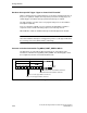
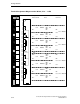
Block Diagram of the SM 431; AI 8 13 Bit
A
D
+5V
0V
CH1
CH7
CH0
+5V
–5V
0V
Suppressor circuit, current jumpering
MV0+
MI0+
MI0+
M0–
CH1
CH7
F_CON
Bus control
M
Bus S7-400
ANA
Front
connector
monitoring
Bus S7-400
Bus S7-400
Figure 5-25 Block Diagram of the SM 431; AI 8 x 13 Bit
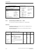
!
Warning
The module can be damaged.
The shunt resistor of an input channel can be destroyed if you inadvertently
connect a voltage sensor to the M–/MI+ terminals of a channel.
Make sure that the front connector wiring corresponds to the following terminal
assignment diagram.