
Programmable Controllers Module Specifications Reference Manual

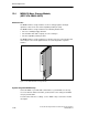


M7-400 Expansions
12-24
S7-400, M7-400 Programmable Controllers Module Specifications
A5E00069467-07
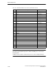
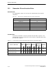
Table 12-7 MSM 478 Parallel Port, Socket X1 (25-Pin Sub D Socket)
Pin
Meaning Direction
1 /STROBE Input/output
2 Data 0 Input/output
3 Data 1 Input/output
4 Data 2 Input/output
5 Data 3 Input/output
6 Data 4 Input/output
7 Data 5 Input/output
8 Data 6 Input/output
9 Data 7 Input/output
10 /ACK Input
11 BUSY Input
12 PE Input
13 SLCT Input
14 /AUTO FEED Output
15 /ERROR Input
16 /RESET Output
17 /SLCT IN Output
18 GND –
19 GND –
20 GND –
21 GND –
22 GND –
23 GND –
24 GND –
25 GND –
Note
Operational ground (GND signal) at the COMa or COMb ports is referenced to
internal ground.
Suitable measures may be required on the process side to avoid ground loops.