Siemens TI305, TI405, TI505 Manuals and Guides Presented By: Siemens Supply For Product Needs Please Visit: http://www.siemenssupply.com/ OR email: sales@siemenssupply.com OR call: 1-800-793-0630 Siemens S7 Manuals Siemens Supply www.siemenssupply.
PanelMate Texas Instruments Communication Driver Manual Eaton Corporation Cutler-Hammer Business Unit 811 Green Crest Drive Columbus, OH 43081
Preface Information in this manual is subject to change without notice and does not represent a commitment on the part of Eaton’s Cutler-Hammer, Inc. Permission is granted to duplicate this material without modification only for your use or the internal use of other members of your company or your agents to assist you in the use and servicing of products purchased from Eaton’s Cutler-Hammer. No permission is granted to modify this material or include this material in a compilation.
y. co pl up ss en ie m .
2 Texas Instruments Communication Driver Manual Support Services The goal of Eaton’s Cutler-Hammer business unit is to ensure your greatest possible satisfaction with the operation of our products. We are dedicated to providing fast, friendly and accurate assistance. That is why we offer you so many ways to get the support you need. Whether it's by phone, fax or mail, you can access Eaton’s Cutler-Hammer support information 24 hours a day, seven days a week. Our wide range of services are listed below.
Table of Contents 3 Table of Contents Introduction....................................................................................................................................... 4 y. co m Introduction .................................................................................................................................... 5 Installing Drivers ............................................................................................................................
4 Texas Instruments Communication Driver Manual Introduction pl y. co m 1 In this chapter, you will learn: About driver installation • How to download drivers to a PanelMate unit • The supported memory types w w w .
Chapter 1: Introduction 5 Introduction m The Operator Station can be used with the programmable controllers in the Texas Instruments (TI) 500 Series (520, 530, 560, and 565), 405 Series (425, 430, and 435), and 305 Series (315, 325, and 330) using the TI driver on the TIHL (Host Link) driver. The driver takes responsibility for communications to the programmable controller, generating the protocol necessary to request information from, and send information to, the PLC.
6 Texas Instruments Communication Driver Manual Downloading Drivers to a PanelMate Unit • In the VCP Transfer Utility, choose the “Executive” tab and select the proper Executive Firmware to download to the PanelMate unit. • Click the button labeled “Add to Operation List.” Choose the “Driver” tab. • Select the appropriate driver to be downloaded to the PanelMate. • Click the button labeled “Add to Operation List.” • Place the PanelMate unit in Serial Transfer Mode.
Chapter 1: Introduction Cable P/N 0818 w w w .s ie m en ss up pl y.
8 Texas Instruments Communication Driver Manual Memory The 500 Series driver supports the following memory types.
Chapter 1: Introduction The 405 Series driver supports the following memory types. Memory Type Memory Address Timer CNT Count V User Data V System Parameter Memory Type Memory Address y. co TMR m 16-Bit Word Remote I/O X Input Y Output C Control Relays S Stages T Timer Relays (Read Only) up GX pl Byte or Bit Counter Relays (Read Only) SP Special Relays (Read Only) w w w .
10 Texas Instruments Communication Driver Manual The 305 Series driver supports the following memory types. Memory Type Memory Area 16-Bit Word Timer/Counter Accumulator (Read Only - Model 315) R Data Registers (Not Supported - Model 315) Memory Type Memory Area m AC R Data Registers (Not Supported – Model 315) (Read Only – Models 325 and 330) Memory Type Memory Area Bit y.
Chapter 1: Introduction Memory Ranges for the 500 Series Driver PLC Type 16-Bit word 520 530 560 565 WX 1-1023 1-1023 1-8192 1-8192 WY 1-1023 1-1023 1-8192 1-8192 V 1-1024 1-5120 1-228352 1-228352 DSP 1-30 1-30 1-1152 1-1152 DSC 1-30 1-30 1-1152 1-1152 DCC 1-30 1-30 1-1152 TCP 1-128 1-400 1-10240 TCC 1-128 1-400 1-10240 DCP 1-30 1-30 1-1152 LPV -- -- -- 1-64 LMN -- -- -- 1-64 LSP -- -- LMX -- -- Memory Type PLC Type Bit 520 X w w w 1-1024
12 Texas Instruments Communication Driver Manual Memory Ranges for the 405 Series Driver The 405 Series driver supports the following memory types and ranges. Memory Type Memory Address V Memory Addresses Timer TMR0-TMR177 V00000-V00177 Counter CNT0-CNT177 V01000-V01177 User Data V01400-V07377 V01400-V07377 System Param V07400-V07777 V07400-V07777 Memory Type Memory Address y.
Chapter 1: Introduction 13 Memory Ranges for the 305 Series Driver The 305 Series driver supports the following memory types and ranges.
14 Texas Instruments Communication Driver Manual Possible Configurations pl y. co m 2 In this chapter, you will learn: up How to connect an operator station to Texas Instruments PLCs w w w .
Chapter 2: Possible Configurations Direct Connection y. co m See the TI manual for your PLC to set the baud rate for the port on the CPU. ss up pl Connection to a DCPM w w w .
16 Texas Instruments Communication Driver Manual Cabling pl y. co m 3 In this chapter, you will learn: up The cabling requirements for Texas Instruments PLCs w w w .
Chapter 3: Cabling Communication between the Operator Station and the TI PLCs Communications between the Operator Station and TI 500 PLCs is achieved via RS232. Communications between the 405 and 305 PLCs can be achieved via RS232 or RS422. The maximum cable length when using RS232 is 50 feet, while the maximum cable length for RS422 is 4000 feet. RS422 cable must be a twisted double-wire shielded cable. m A 15-foot PLC cable can be purchased from Cutler-Hammer.
18 Texas Instruments Communication Driver Manual y. co m Cable Catalog Number: TI23 RS422 Cabling for TI 305, 405, 435, 505, 545, and 555 PLCs en ss up pl Cable Catalog Number: TI24A w w w .
Chapter 3: Cabling m Cable Catalog Number: TI26A w w w .s ie m en ss up pl y.
20 Texas Instruments Communication Driver Manual RS232C Cabling for TI PLCs w w w .s ie m en ss up pl y. co m The Operator Stations that have RJ-11 6-wire and RJ-45 modular jacks must have cables configured with modular connections.
Chapter 3: Cabling w w w .s ie m en ss up pl y.
22 Texas Instruments Communication Driver Manual Communication Parameters In this chapter, you will learn: up The different switch settings w w w .s ie m en ss • pl y.
Chapter 4: Communications Parameters 23 Dual Communication Port Module TI 500 Series m The Dual Communication Port Module (DCPM) has two RS232/423 ports that work independently and permit simultaneous communication. The Operator Station does not support RS423. RS232 must be used for communications. The two ports are identical to the programming port on the PLC. All communication is serial with one stop bit at all baud rates, except at 110 baud, which has two stop bits.
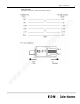
24 Texas Instruments Communication Driver Manual Serial Interface Port TI 435 PLC w w w .s ie m en ss up pl y. co m The Serial Interface Port enables the TI 435 PLC to interface directly to the Operator Station. The figure below shows the TI 435 Serial Interface Port.
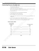
Chapter 4: Communications Parameters 25 Name Pin Name 1 Not Used 14 TXD+ 2 TXD 15 Not Used 3 RXD 16 TXD- 4 RTS 17 Not Used 5 CTS 18 RTS- 6 Not Used 19 RTS+ 7 SG 20 Not Used 8 Not Used 21 Not Used 9 RXD+ 22 Not Used 10 RXD- 23 CTS- 11 CTS+ 24 Not Used 12 Not Used 25 Not Used up pl y. co Pin m The table below shows the pinouts for the Serial Interface Port. en ss Communication to the TI 435 is through the Host Link Protocol in Master/Slave mode.
26 Texas Instruments Communication Driver Manual Dipswitch Settings The dipswitch block is located at the rear of the CPU. The table below summarizes the dipswitch settings for the CPU dipswitch. ON OFF SW1 CPU Battery CPU battery enabled SW2 Station Address is 1 Station address is set via MIU (Machine Interface Unit) or programming software SW3 Baud rate selection for Serial Interface Port SW4 Baud rate selection for Serial Interface Port y.
Chapter 4: Communications Parameters Data Communication Module (DCM) TI 405 Series m The Data Communication Module (DCM) enables the TI Series 405 PLCs to interface with the Operator Station. The DCM supports the Hostlink protocol either Master/Slave or Peer-to-Peer. In the Master/Slave configuration, the Operator Station will be the Master device and the DCM will be the slave device in both the Point-to-Point and the Multidrop configurations.
28 Texas Instruments Communication Driver Manual There are two rotary switches on the DCM that select the network address of the PLC. This address must match the assigned PLC ID in the PLC Name and Port Table. There are two dipswitches located on the DCM. Dipswitch 1 sets the communication parameters. Switches 1, 2, and 3 of dipswitch 1 select the baud rate. Switch 4 sets the parity. Switch 5 must be set to OFF. Switches 6 through 8 set the Response Time Delay. This should be set to 0ms. ss up pl y.
Chapter 4: Communications Parameters Switch 3 and 4 of dipswitch 2 should be set to OFF to enable communication timeout and to allow data to be transmitted in hexadecimal. y. co m Dipswitch 2 The following parameters are the default port characteristics of the DCM. w w w .
30 Texas Instruments Communication Driver Manual Data Communication Unit (DCU) TI 305 Series m The Data Communication Unit (DCU) enables the TI Series 305 PLCs to interface with external devices. The DCU only supports the master/slave protocol. The Operator Station will be the master device and the DCU will be the slave. When selecting a port use in the PLC Name and Port Parameters Table, use TI-HL/M (Texas Instruments Hostlink master/slave). The two DCU models are 305-02DM and 305-03DM.
Chapter 4: Communications Parameters 31 There are two dipswitches located on the DCU. Dipswitch 1 selects the baud rate and internal functions. Switches 1 and 2 of dipswitch 1 select the baud rate. Switches 3 through 8 select the internal functions of dipswitch 1. See the following tables for the recommended settings.
32 Texas Instruments Communication Driver Manual Bit Writes with Ladder Logic – 405 Series Register 2 Register 3 up Register 4 This register contains a 16-bit mask in which the bit position to be set will be set to 1 and all other bits will be set to 0. Each memory type has a corresponding V memory address. Register 2 contains the V memory address in which the bit to be set is located.
w w w .s ie m en ss up pl y.
Texas Instruments Communication Driver Manual w w w .s ie m en ss up pl y.
Chapter 4: Communications Parameters 35 Bit Writes with Ladder Logic – Model 315 y. co m The Texas Instruments Hostlink Protocol does not permit an external intelligent device to directly alter the state of a single bit without over-writing the entire byte in which the bit exists. As a result, the Operator Station will write values to designated registers in the PLC, specifying which bit should be set or cleared.
36 Texas Instruments Communication Driver Manual PLC ID The format for the PLC ID for the model 315 will include both the PLC ID and a memory register used for the two Bit Write registers. The format will be the PLC ID followed by the memory address. XX-IOYYY or XX-YYY or XX Where Note: m PLC ID in range 1-90 PLC ID/memory address separator Optional memory type Optional Starting IO byte memory address in range 0-340. y. co XX IO YYY In the PLC ID field, IO will default to a byte address.
Chapter 4: Communications Parameters 37 Bit Writes with Ladder Logic – Models 325 and 330 m The Texas Instrument Hostlink Protocol does not permit an external intelligent device to directly alter the state of a single bit without overwriting the entire byte in which that bit exists. As a result, the Operator Station will write to a designated register in the PLC, specifying which bit should be set or cleared.
38 Texas Instruments Communication Driver Manual w w w .s ie m en ss up pl y. co m If an AC memory address in not entered, the Bit Write register will default to AC677.
Chapter 5: Word and Bit References Word and Bit References pl y. co m 5 In this chapter, you will learn: up How to configure word and bit references w w w .
40 Texas Instruments Communication Driver Manual Word Referencing Method The general word referencing method is: [plcname,word#format] m The "plcname" is the name of the designated PLC as listed in the PLC Name and Port Table. The "word" is the reference number (address) of the word or register to be read or written. The "#format" is a code which specifies the format of the data being read or written. The "plcname" and "#format" are optional. The general bit referencing method is: y.
Chapter 5: Word and Bit References TI 405 Series Word, Byte, and Bit References Texas Instruments 405 PLCs use octal word addresses. The Operator Station format default is U16. The following is the format for a register reference. [XY] X Y Memory type (TMR, CNT, and V) Word address (leading zeroes not required) m To reference a byte value, the memory address must be on an 8-bit boundary. The following is the format for an 8-bit (byte) reference. y.
42 Texas Instruments Communication Driver Manual TI 305 Series Word and Bit References Texas Instruments 305 PLCs use octal word addresses. The Operator Station format default is U16. The following is the format for a register reference. [XY] Note: Memory type (AC and R - for 325 and 330 models) Word address (leading zeroes not required) The Data Register (R) is 8-bits with this format. The following is the format for a 16-bit data register reference. W : R Y y.
Chapter 5: Word and Bit References The following is the format for a bit referenced within a word. [XY/B] Memory type (AC and R - for 325 and 330 models) Word address (leading zeroes not required) Delimiter to separate bit number Bit number in the range (0-17, 0-7 for Data Register) or [W:RY/B] Designating word reference Word designator/address separator Memory type (R - for 325 and 330 models) Word address Delimiter to separate bit number Bit number in the range (0-17) pl y.
44 Texas Instruments Communication Driver Manual Examples The following are examples of valid PLC references that may be assigned in the Operator Station expression fields.
Chapter 5: Word and Bit References 405 Series Reference Description [TMR11] Timer register 12 [CNT30] Counter register 30 [V24] User Data register 22 m Word References [B:GX10] Remote I/O register 10 [B:X20] Input register 20 [B:Y100] Output register 100 [B:C30] Control relay register 30 [B:S40] Stage register 40 [B:T50] Timer relay register 50 [B:CT170] Counter relay register 170 [B:SP0] Special relay register 0 pl Description up Reference y.
46 Texas Instruments Communication Driver Manual 305 Series Word References Reference Description [AC614] Timer/Counter register 614 [W:R502] Data register 502 (325 or 330 models only) Description [R12] Data register 12 (325 or 330 models only) [B:T611] Timer register 611 [B:SG20] Stage register 20 Bit References Description [IO12] Input/Output register 12 [T617] Timer element 617 [C622] Counter element 622 [TC600] Timer/Counter element 600 [SG43] Stage element 43 [W:R510/11] Bit
Chapter 6: Maintenance Access Maintenance Access pl y. co m 6 In this chapter, you will learn: up How to use the Maintenance Template w w w .
48 Texas Instruments Communication Driver Manual Maintenance Access The Maintenance Template will access all memory locations supported by the PLC driver as defined in this manual. When running online, you may change the PLC reference. The Maintenance Template is designed to assist you in specifying the PLC reference by scrolling through a list of mnemonics that are used to enter the PLC word reference. When online in the PLC reference change mode, the following list is available.
Index 305 Series, 13 405 Series, 12 500 Series, 11 Memory Types, 8 305 Series, 10 405 Series, 9 500 Series, 8 B Bit Writes with Ladder Logic 315 Model, 35 325 and 330 Models, 37 405 Series, 32 C y.
Reader Comment Card Cutler-Hammer strives to provide quality user guides and product manuals. Please take a moment to fill out this comment card.