! & %*$) ' $ % ' % *" ( ' $* " ' ' *# ' $* " (( # "+ *# ' '! !$ " !)!%$
Copyright 1994 by Siemens Industrial Automation, Inc. All Rights Reserved — Printed in USA Reproduction, transmission or use of this document or contents is not permitted without express consent of Siemens Industrial Automation, Inc. All rights, including rights created by patent grant or registration of a utility model or design, are reserved. Since Siemens Industrial Automation, Inc.
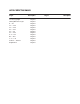
MANUAL PUBLICATION HISTORY SIMATIC TI505 High Speed Counter Encoder Module (PPX:505–7003) User Manual Order Manual Number: PPX:505–8127–1 Refer to this history in all correspondence and/or discussion about this manual.
LIST OF EFFECTIVE PAGES Pages Cover/Copyright History/Effective Pages iii — xiv 1-1 — 1-23 2-1 — 2-13 3-1 — 3-17 4-1 — 4-5 5-1 — 5-21 A-1 — A-8 B-1 — B-8 C-1 — C-8 Index-1 — Index-5 Registration Description Original Original Original Original Original Original Original Original Original Original Original Original Original Pages Description
Contents Preface About this Manual . . . . . . . . . . . . . . . . . . . . . . . . . . . . . . . . . . . . . . . . . . . . . . . . . . . . . . . . . . . . . . Related Manuals . . . . . . . . . . . . . . . . . . . . . . . . . . . . . . . . . . . . . . . . . . . . . . . . . . . . . . . . . . . . . . . Agency Approvals . . . . . . . . . . . . . . . . . . . . . . . . . . . . . . . . . . . . . . . . . . . . . . . . . . . . . . . . . . . . . . Technical Assistance . . . . . . . . . . . . . . . . . . . . . . . . .
1.8 Compare Output . . . . . . . . . . . . . . . . . . . . . . . . . . . . . . . . . . . . . . . . . . . . . . . . . . . . . . . . . . . . . . . Compare Toggle Output . . . . . . . . . . . . . . . . . . . . . . . . . . . . . . . . . . . . . . . . . . . . . . . . . . . . . . . . Latch Output . . . . . . . . . . . . . . . . . . . . . . . . . . . . . . . . . . . . . . . . . . . . . . . . . . . . . . . . . . . . . . . . . . . Outputs in Non-recycle Mode . . . . . . . . . . . . . . . . . . . . . . . . . . . . .
Chapter 3 3.1 3.2 3.3 3.4 3.5 Understanding Module Operation Module I/O Map . . . . . . . . . . . . . . . . . . . . . . . . . . . . . . . . . . . . . . . . . . . . . . . . . . . . . . . . . . . . . . . . 3-2 PLC-to-Module Communications Overview . . . . . . . . . . . . . . . . . . . . . . . . . . . . . . . . . . . . . . I/O Word Definitions . . . . . . . . . . . . . . . . . . . . . . . . . . . . . . . . . . . . . . . . . . . . . . . . . . . . . . . . . . . . . I/O Words Grouped by Counter . . . . .
3.6 3.7 Clear Output Latches Bits: WY20.07 and WY20.08 . . . . . . . . . . . . . . . . . . . . . . . . . . . . . . . . . 3-11 Setting Preset Values and Programming Options for Channel 1 . . . . . . . . . . . . . . . . . . . . 3-12 Channel 1, 24-Bit Counter 1, Preset 1 . . . . . . . . . . . . . . . . . . . . . . . . . . . . . . . . . . . . . . . . . . . . . Channel 1, 24-Bit Counter 1, Preset 2 . . . . . . . . . . . . . . . . . . . . . . . . . . . . . . . . . . . . . . . . . . . . .
5.5 5.6 5.7 5.8 5.9 5.10 24-Bit Counter Input Jumper Selection . . . . . . . . . . . . . . . . . . . . . . . . . . . . . . . . . . . . . . . . . . . 5-8 Input A Jumper . . . . . . . . . . . . . . . . . . . . . . . . . . . . . . . . . . . . . . . . . . . . . . . . . . . . . . . . . . . . . . . . . 1 µs Jumper . . . . . . . . . . . . . . . . . . . . . . . . . . . . . . . . . . . . . . . . . . . . . . . . . . . . . . . . . . . . . . . . . . . . Counter 2 [5] or Counter 3 [6] Jumpers . . . . . . . . . .
A.3 A.4 Cascade Counting Applications . . . . . . . . . . . . . . . . . . . . . . . . . . . . . . . . . . . . . . . . . . . . . . . . . A-6 32-Bit Cascade Counting . . . . . . . . . . . . . . . . . . . . . . . . . . . . . . . . . . . . . . . . . . . . . . . . . . . . . . . A-6 Prescale Counting Applications . . . . . . . . . . . . . . . . . . . . . . . . . . . . . . . . . . . . . . . . . . . . . . . . . A-7 16-Bit Prescale 16-Bit Counting . . . . . . . . . . . . . . . . . . . . . . . . . . . . . . .
List of Figures Figure 1-1 Figure 1-2 Figure 1-3 Figure 1-4 Figure 1-5 Figure 1-6 Figure 1-7 Figure 1-8 Figure 1-9 Figure 1-10 Figure 1-11 Figure 1-12 Figure 1-13 Figure 1-14 Figure 1-15 Figure 1-16 Figure 1-17 Physical Features of the High Speed Counter Encoder Module . . . . . . . . . LED Indicators . . . . . . . . . . . . . . . . . . . . . . . . . . . . . . . . . . . . . . . . . . . . . . . . . . . . . . . High Speed Counter Input/Output Functional Diagram . . . . . . . . . . . . . . . .
Figure C-1 Figure C-2 Figure C-3 Figure C-4 Figure C-5 x Contents Input Specifications . . . . . . . . . . . . . . . . . . . . . . . . . . . . . . . . . . . . . . . . . . . . . . . . . Filtering Noise from Input Signal . . . . . . . . . . . . . . . . . . . . . . . . . . . . . . . . . . . . . . Minimum High and Low Pulse Widths for 100 kHz Signal . . . . . . . . . . . . . . . . Pulse Width Requirements for Quadrature Filtering at 100 kHz . . . . . . . . . . Peak vs. Continuous Current Output . . . . . . .
List of Tables Table 1-1 Binary Counting Outputs . . . . . . . . . . . . . . . . . . . . . . . . . . . . . . . . . . . . . . . . . . . . . . Table 1-2 Divide-by-N Counting Outputs . . . . . . . . . . . . . . . . . . . . . . . . . . . . . . . . . . . . . . . . 1-16 1-16 Table 2-1 I/O Connections . . . . . . . . . . . . . . . . . . . . . . . . . . . . . . . . . . . . . . . . . . . . . . . . . . . . . Table 2-2 Features of Electronic Drives . . . . . . . . . . . . . . . . . . . . . . . . . . . . . . . . . .
Table C-1 Table C-2 Table C-3 Table C-4 xii Contents Physical and Environmental Specifications . . . . . . . . . . . . . . . . . . . . . . . . . . . . Input Voltage and Current Specifications . . . . . . . . . . . . . . . . . . . . . . . . . . . . . Output Specifications . . . . . . . . . . . . . . . . . . . . . . . . . . . . . . . . . . . . . . . . . . . . . . . . Module Response Times . . . . . . . . . . . . . . . . . . . . . . . . . . . . . . . . . . . . . . . . . . . . . .
Preface About this Manual Related Manuals This manual describes the SIMATIC TI505 High Speed Counter Encoder Module. The following major topics are covered: • Overview of product features. • Hardware installation and wiring procedures. • Quick start procedure using the default configuration. • Basic concepts of operation. • Configuring optional modes of operation. • Applications. • Troubleshooting. • Product specifications.
Agency Approvals Series 505 products have been developed with consideration of the draft standard of the International Electrotechnical Commission Committee proposed standard (IEC-65A/WG6) for programmable controllers (released as IEC 1131–2, Programmable Controllers Part 2: Equipment Requirements and Tests, First Edition, 1992–09). This module meets the standards of the following regulatory agencies: • Underwriters Laboratories, Inc.
Chapter 1 Product Overview 1.1 Physical Features of the Module . . . . . . . . . . . . . . . . . . . . . . . . . . . . . . . . . . . . . . . . . . . . . . . . . 1-2 1.2 Functional Features of the Module . . . . . . . . . . . . . . . . . . . . . . . . . . . . . . . . . . . . . . . . . . . . . . . 1-4 1.3 Quadrature Modes of Counting . . . . . . . . . . . . . . . . . . . . . . . . . . . . . . . . . . . . . . . . . . . . . . . . . . 1-7 1.4 Non-Quadrature Modes of Counting . . . . . . . . . . . . .
1.1 Physical Features of the Module Physical Features The SIMATIC TI505 High Speed Counter Encoder Module (PPX:505–7003) is a single-wide input/output module that communicates with the PLC when installed in a TI505 system. The physical features of the module are shown in Figure 1-1.
LED Indicators The High Speed Counter Encoder Module (HSCE) provides a total of ten LED indicators on the faceplate. See Figure 1-2. • Eight red LEDs indicate the on/off status of outputs 1 through 8. • A red LED labeled MOD GOOD indicates that the module is powered up and has not detected any hardware or software failure. • A green LED labeled RUN indicates that the module is in Run mode. It flashes when the module is first powered up, before it has been programmed (configured) from the PLC.
1.2 Functional Features of the Module Summary of Counters and Outputs The HSCE module provides a total of six counters and eight outputs, divided into two channels. Each channel contains the following: • One 24-bit counter: this counter has two pulse inputs, A and B; its primary purpose is to count pulses from an incremental pulse encoder. • Two 16-bit counters: each counter has a single input, C or D, in each channel; its primary purpose is simple pulse counting, up or down.
Additional Module Features The HSCE module allows you to connect counters internally for cascaded counting. The module also provides Immediate I/O operation as well as Interrupt I/O capability (using Task 8 to execute interrupt handling routines). To continue the counting operation in case of a loss of power to the I/O base, you can provide back-up power to the module. NOTE: The listed CPU Software releases may not properly allow the module to update the WX words during an immediate I/O Read cycle.
Functional Features of the Module (continued) Functional Diagram Figure 1-3 presents a functional diagram that summarizes the counters and outputs provided by the HSCE module.
1.3 Quadrature Modes of Counting Quadrature Mode Overview Each 24-bit counter, Counter 1 (Channel 1, inputs A & B) and Counter 4 (Channel 2, inputs A & B) provides Quadrature mode counting. When input A pulses lead input B pulses, the count direction is up. When input B pulses lead input A pulses, the count direction is down. The relationship between input A and input B that determines the count direction applies to 1X, 2X, and 4X Quadrature counting modes, described in this section.
Quadrature Modes of Counting (continued) 2X Quadrature Counting Mode When set to 2X Quadrature Mode, the module counts both edges of input A pulses, in both count directions. Figure 1-5 shows the relationship between inputs A and B, and the count value that results using 2X quadrature mode.
1.4 Non-Quadrature Modes of Counting Up/Down Counting Overview When you select the up/down counting mode, two input pulse signals determine the count value. (Refer to Figure 1-7.) • With input B high, the count increments on the rising edge of input A. • With input A high, the count decrements on the rising edge of input B. For proper counting, the input without the clock must be held high or on; otherwise, the count value that results cannot be defined.
1.5 Counting with the 24-Bit Counters Binary Counting, Recycle Mode In binary recycle mode, the counter counts up or down on each input pulse. In the count-up direction, a carry signal is generated when the counter overflows (see note). In the count-down direction, a borrow signal is generated when the count underflows (see note). When the count equals the preset value, the output signal pulses, toggles, or latches, depending on the output option you select.
Divide-by-N Counting, Non-Recycle Mode In divide-by-N non-recycle mode, a preset value is loaded into the counter. The counter counts up or down on each input pulse. In the count-up direction, when the counter overflows, it generates a carry signal. In the count-down direction, when the count underflows, it generates a borrow signal. When a carry or borrow signal occurs, the counter stops.
1.6 24-Bit Counters Quadrature Mode Outputs You can select one of four output options, (see Figure 1-9) for the output signal of each 24-bit counter (Counter 1, Output 1; and Counter 4, Output 5). Outputs in Quadrature Modes In quadrature counting modes, the internal clocking for the Compare, Carry and Borrow pulses produce a pulse width insufficient to drive the outputs. See Figure 1-9. Compare Toggle and Compare Latch are the only signals that can drive the output circuitry.
Input A Pulse Input B Pulse X4 Count X2 Count X1 Count –5 –4 –2 –1 –3 –2 –1 –1 0 0 0 1 2 1 3 4 2 1 5 6 3 7 8 4 2 9 5 4 2 1 3 2 1 1 0 0 0 –1 –2 –1 –3 –4 –2 –1 Carry Toggle Borrow Toggle Compare Toggle Compare Latch Figure 1-9 24-Bit Quadrature Mode Outputs High Speed Counter Encoder Module User Manual Product Overview 1-13
1.7 24-Bit Counters Non-Quadrature Mode Outputs Non-quadrature Modes In non-quadrature counting modes, the internal clocking for the Compare, Carry and Borrow pulses are one-half of the input clock width. You can select one of four options for the output signal of each 24-bit counter (Counter 1, Output 1; and Counter 4, Output 5) in Up counting and Down counting modes. Carry Toggle Output The Carry Toggle output, in Up counting mode, changes state when the count overflows. See Figure 1-10.
Pulse Input –3 –2 –1 0 1 2 3 4 5 6 7 Carry Carry Toggle Rollover Compare Compare Toggle Latch Figure 1-10 24-Bit Counter Output Up Counting Pulse Input 7 6 5 4 3 2 1 0 –1 –2 Borrow Borrow Toggle Rollover Compare Compare Toggle Latch Figure 1-11 24-Bit Counter Output Down Counting High Speed Counter Encoder Module User Manual Product Overview 1-15
24-Bit Counters Non-Quadrature Mode Outputs (continued) Outputs in Non-recycle Mode Outputs in Divide-by-N Mode In non-recycle counting mode, Compare, Carry, and Borrow pulses are not generated. Carry Toggle and Borrow Toggle signals are the cycle completion indicators. At the end of a cycle, additional input count pulses are ignored. One of the following conditions is required to restart the counter: • An external INDEX pulse (when WY21.07, or WY27.07, or both are set). • A PLC counter reset (WY19.
1.8 Counting with 16-Bit Counters 16–Bit Counter General Description General information for all 16-bit counter modes is presented in following paragraphs. Figure 1-12 shows that incrementing or decrementing the count value occurs on the rising edge of the input clock signal. A valid clock is a high-to-low-to-high transition; or from the input viewpoint, the clock input goes from On-to-Off-to-On. A trigger is an On–to-Off pulse edge.
Counting with 16-Bit Counters (continued) 16-Bit Counter Modes You can select a 16-bit counter mode by setting the appropriate bits in the Setup Word (WY20). Cascade counting requires that a jumper be configured. You can configure the 16-bit counters to count in one of the following modes: • Retriggerable one-shot. • Divide-by-N, 16-bit counting. • Triggered Strobe. • Square Wave generator. • Cascade counting.
Retriggerable One-Shot The retriggerable one-shot mode generates an output that is On (high), from the first clock after a trigger, and remains On until the preset number of clocks have been counted down to zero. The output is On for the preset number of clocks. See Figure 1-13. Twenty is an arbitrary starting count value. The waveforms show that the first clock pulse after the trigger transitions the output On (high), and the counter counts down from the preset value (2).
Counting with 16-Bit Counters (continued) Divide-by-N Divide-by-N counting generates an output that is On for one clock period every count cycle. The length of the count cycle is the preset number of clocks. The counter counts down from the preset value to 1. The first valid clock pulse, after the gate, loads the preset value (3) and starts decrementing the counter. When the count value is 1, the output turns On.
Triggered Strobe The triggered strobe mode generates an output that is On for one clock period following the trigger, after the preset number of clocks has been down counted to zero. The output turns On when the preset number of clocks has been counted to zero, or (preset value +1) clocks after the trigger pulse. To repeat a cycle, a trigger is required. A trigger can be an external input or the PLC can set the Reset Counter flag, WY19.03, .04, .07, or .08 for the corresponding counter 2, 3, 5, or 6.
Counting with 16-Bit Counters (continued) Square-Wave Generator Even Preset Value The square-wave generator generates an active output for one-half of the preset number of clocks. The length of the down count cycle is the preset number of clocks. For an even preset count, the preset is loaded, the output is Off, and the counter starts decrementing by two after the first clock pulse. The output turns On when the count value is zero.
Square Wave Generator Odd Preset Value For an odd preset value, the preset – 1 value is loaded, and the counter starts decrementing by two after the first clock pulse. The output turns On when the count value is zero and would underflow, however, the counter automatically reloads the preset + 1 value into the counter and starts decrementing by two. The output turns Off when the count value is zero again. The counter automatically reloads the preset – 1 value into the counter and starts decrementing by two.
Chapter 2 Installing the Module 2.1 2.2 2.3 2.4 2.5 Overview of Installation . . . . . . . . . . . . . . . . . . . . . . . . . . . . . . . . . . . . . . . . . . . . . . . . . . . . . . . . . 2-2 Flow of Tasks . . . . . . . . . . . . . . . . . . . . . . . . . . . . . . . . . . . . . . . . . . . . . . . . . . . . . . . . . . . . . . . . . . . . Handling the Module . . . . . . . . . . . . . . . . . . . . . . . . . . . . . . . . . . . . . . . . . . . . . . . . . . . . . . . . . . . Visual Inspection . .
2.1 Overview of Installation Flow of Tasks Figure 2-1 shows the flow of tasks to follow when you install this module. Configure counter mode of operation (See Chapters 3, 4, and 5.) Chapter 4 describes the default configuration of the module. Insert module into I/O base. Connect I/O wiring to the terminal block. Power up and check status of LEDs. Configure I/O address in controller memory.
2.2 ! Inserting the Module into the Base WARNING Inserting the Module To minimize potential shock, turn off power to the I/O base and to any modules installed in the base before inserting or removing a module, or installing a terminal block. Failure to do so may result in potential injury to personnel or damage to equipment. The HSCE module is a single-wide module. You can insert it into any available I/O slot on a Series 505 I/O base. To install the module, follow these steps. 1.
2.3 Wiring the Module I/O Connections You should wire all of your input and output signals to the HSCE module removable terminal block.
PPX:2587705–8010 Side-accessible PPX:2587705–8011 Front-accessible 12 Volts DC Class 2 Power Supply Back-up Power +12V Back-up Power RTN Ch1 A+ Ch1 A– Ch1 B+ Ch1 B– Ch1 C+ Ch1 C– Ch1 D+ Ch1 D– Ch1 INDEX+ Ch1 INDEX– Ch1 RESET+ Ch1 RESET– Ch1 INHIBIT+ Ch1 INHIBIT– Ch2 A+ Ch2 A– Ch2 B+ Ch2 B– Ch2 C+ Ch2 C– Ch2 D+ Ch2 D– Ch2 INDEX+ Ch2 INDEX– Ch2 RESET+ Ch2 RESET– Ch2 INHIBIT+ Ch2 INHIBIT– User Power (PWR+) 24 Volts DC Class 2 Power SUpply PWR +24V RTN Output 1 Output 2 Output 3 Output 4 Output 5 Output 6 O
Wiring the Module (continued) Wiring the Terminal Block You wire the HSCE module by wiring the user power supply and input and output signals. All connections are made at the terminal block. To wire the terminal block, follow the procedure below. 1. Turn the terminal block, with the screw-heads facing you, until the A series of terminals is at the top and the D series is at the bottom. 2. Start with the D series and loosen the appropriate terminal block screws. 3.
Wiring the Inputs Input connections to the module can be electronic output drive devices or mechanical switches. Figure 2-4 shows an example of wiring electronic encoder outputs to the input terminals of the module for a non-inverted signal. Module V A+ OCI Encoder Constant current load A– Input Input OCI On Figure 2-4 Non-Inverted Input Drive Figure 2-5 shows an example of wiring electronic encoder outputs to the input terminals of the module for an inverted signal.
Wiring the Module (continued) Figure 2-6 shows an example of wiring differential line drive inputs. Module Encoder A+ OCI + _ Input Constant current load A– Input OCI On Figure 2-6 Differential Line Drive Table 2-2 Features of Electronic Drives Open Collector or Single-Ended 2-8 Differential Drives • 5 to 24 V • Normally 5 V • Source or sink • Polarity selection • Polarity selection • • Multiple input drive capability Voltage and current ratings may not drive input.
Figure 2-7 shows an example of wiring mechanical switch inputs. (Note that with mechanical switches, the contacts can “bounce” when switched.
Wiring the Module (continued) Wiring the Outputs Figure 2-8 shows an example of output wiring. +24 V To 7 other outputs Power supply fuse: 100 mA + Total Load Current* Output Drive Output fuse: Rated load current* Load Inductive Load Protection *External fuses provided by user must conform to accepted wiring practives required by the installation.
Connecting the Terminal Block To connect the terminal block to the module, follow these steps. (See Figure 2-9.) 1. Align the terminal block with the edge card connector on the bezel. 2. Press firmly at both ends of the terminal block until it is seated. 3. Tighten the screws at the top and bottom. Do not over-tighten. Not Available in Electronic Format. Refer to your hard copy.
2.4 Powering Up the Base Supplying Power to the I/O Base Refer to the system manual for your controller for information on installing and wiring the power supply for your I/O base. Follow all installation guidelines and safety considerations described in your system manual before powering up the system. After installing the module, power up the I/O base and observe the status of the LEDs on the front of the module. (Refer to Figure 2-10.
2.5 Configuring I/O Addresses in the Controller After installing the module in the I/O base, you must assign the I/O starting address in your programmable controller (PLC) memory. (The module is not automatically assigned an I/O address in the controller.) NOTE: Even though the module may appear to be operating correctly, it does not communicate with the PLC unless it is configured in the I/O map. To confirm the I/O map and verify controller-to-module communications, connect a PLC programming device (e.
Chapter 3 Understanding Module Operation 3.1 Module I/O Map . . . . . . . . . . . . . . . . . . . . . . . . . . . . . . . . . . . . . . . . . . . . . . . . . . . . . . . . . . . . . . . . 3-2 3.2 Data Formats . . . . . . . . . . . . . . . . . . . . . . . . . . . . . . . . . . . . . . . . . . . . . . . . . . . . . . . . . . . . . . . . . . . 3-4 3.3 Reading Module Status . . . . . . . . . . . . . . . . . . . . . . . . . . . . . . . . . . . . . . . . . . . . . . . . . . . . . . . . . . 3-6 3.
3.1 Module I/O Map PLC-to-Module Communications Overview The HSCE module communicates with the PLC using word inputs and word outputs. The PLC reads current count values, holding registers, and module status bits from word inputs. Word outputs contain user-defined counter configuration setups and preset values. I/O Word Definitions Table 3-1 lists the definitions for the word inputs (WX) and the word outputs (WY), relative to a starting address of 1.
I/O Words Grouped by Counter Figure 3-1 shows how the WX and WY words are grouped by counter to help you configure each counter in the HSCE module.
3.2 Data Formats Current Count and Holding Register Count Value Formats The current count value for each 24-bit counter is contained in two word inputs (for example, WX1 and WX2). • The count range is from 0 to 16,777,215 in unipolar mode. • The count range is from +8,388,607 to –8,388,608 in bipolar mode. • Overflow and underflow occur at the 0 value. Table 3-2 shows the word format for the current count and Holding Register values for the 24-bit counters (Counters 1 and 4).
24-Bit Preset and Configuration Formats Each 24-bit counter has two preset values to control two outputs, as listed in Table 3-1 and shown in Figure 3-1. The 24-bit unipolar value for each preset is contained in the lower byte of the most significant word and both bytes of the least significant word, as shown by the shaded areas in Table 3-3. The upper byte of the most significant word is used to configure the counters and outputs.
3.3 Reading Module Status Module Status Words The PLC reads the module status bits in word inputs WX17 and WX18. The on/off status of the eight outputs, count direction, interrupts, module mode, error conditions, and other indicators are contained in these words, listed in Table 3-6. (Status word format is shown in Table 3-5.
The following paragraphs provide expanded definitions for status word WX18. WX18.01, RUN Mode RUN mode flag is set when the module is in the Run Mode. The flag is cleared in Program Mode or when an error has been detected. When the module is not in the Run Mode, the output drive and Interrupt functions are disabled. WX18.02, Presets Updated The presets updated flag indicates that the module has updated the counters with Preset values. Requested when WY20.02 is set. All counters are affected. WX18.
3.4 Configuring Program Mode Setup Words Setup Words: Program Mode You can use WY19 and WY20 to choose specific counter input or output options in Program Mode, as listed in Table 3-8. (The format is shown in Table 3-7.) Table 3-7 Module Setup Words Word MSByte LSByte WY19 1 2 3 4 5 6 7 8 9 10 11 12 13 14 15 16 WY20 1 2 3 4 5 6 7 8 9 10 11 12 13 14 15 16 Table 3-8 Bit Definitions for the Program Mode Setup Words Word.
The following paragraphs provide expanded definitions for setup words WY19 and WY20 in Program mode. Program Mode Definitions At the start of Program Mode, all counters are inhibited and reset. When programming is complete, WX18.02 is set and WY19.01 through WY19.08 function normally. Interrupt Enable Bits: WY19.09 through WY19.16 In Program Mode, when you set any Interrupt Enable bit, the corresponding output is programmed as an interrupt source.
3.5 Configuring Run Mode Setup Words Setup Words: Run Mode Table 3-9 shows that you can use WY19 and WY20 to choose specific counter input or output options that are programmable when the module is in Run Mode. These options can be selected only with bit WY20.01 cleared, which puts the module in Run Mode. Table 3-9 Bit Definitions for the Run Mode Setup Words Word.Bit Description of Bit Functions for RUN Mode WY19.01 WY19.02 WY19.03 WY19.04 Ch1, Counter 1: Inhibit; counting pauses while set.
The following options can only be selected with bit WY20.01 cleared, which puts the module in Run Mode. Inhibit Bits: WY19.01 and WY19.05 While the inhibit bit is set, it inhibits (pauses) the counting of Counter 1 and bit WY19.05 inhibits the counting of Counter 4. Reset Bits: WY19.02 and WY19.06 When set, Reset Counter 1 (WY19.02) and Counter 4 (WY19.06) clears the count value to 0. The reset bit provides the Reset-and-Go function. Reset Bits: WY19.03, 04 and WY19.
3.6 Setting Preset Values and Programming Options for Channel 1 Channel 1, 24-Bit Counter 1, Preset 1 The lower byte of WY21 and all of WY22 contain the Preset 1 24-bit integer value. Use the upper byte of WY21 to configure programming values. Together, the preset value and the programming values determine the count method and how Output 1 functions when count and preset are equal, or when the count value overflows or underflows. Table 3-10 (shaded areas) shows the word formats.
Channel 1, 24-Bit Counter 1, Preset 2 The lower byte of WY23 and all of WY24 contain the Preset 2 24-bit integer value. Use the upper byte of WY23 to configure programming values. Together, the preset value and the programming values determine the count method and how Outputs 1 and 2 function when the count and preset are equal, or the count value is less than or greater than the counter preset. All preset values are unipolar in format.
Setting Preset Values and Programming Options for Channel 1 (continued) Channel 1, 16-Bit Counter Presets Table 3-14 and Table 3-15 shows the formats for the preset values (0 – 65535) for Counters 2 and 3.
3.7 Setting Preset Values and Programming Options for Channel 2 Channel 2, 24-Bit Counter 4, Preset 5 The lower byte of WY27 and all of WY28 contain the 24-bit integer Preset 5 value. Use the upper byte of WY27 to configure programming values. Together, the preset value and the programmed values determine the count method and how count Output 5 functions when count and preset are equal, or when the count value overflows or underflows.
Setting Preset Values and Programming Options for Channel 2 (continued) Channel 2, 24-Bit Counter 4, Preset 6 The lower byte of WY29 and all of WY30 contain the 24-bit integer Preset 6 value. Use the upper byte of WY29 to configure programming values. Together, the preset value and the programming values determine the count method and how Outputs 5 and 6 function when the count and preset are equal, or when the count value is less than or greater than the counter preset.
Channel 2, 16-Bit Counter Presets Table 3-20 and Table 3-21 shows the formats for the preset values (0 – 65535) for Counters 5 and 6.
Chapter 4 Using the Default Configurations 4.1 4.2 4.3 Default Hardware Modes . . . . . . . . . . . . . . . . . . . . . . . . . . . . . . . . . . . . . . . . . . . . . . . . . . . . . . . . 4-2 Factory Jumper Settings . . . . . . . . . . . . . . . . . . . . . . . . . . . . . . . . . . . . . . . . . . . . . . . . . . . . . . . . . 24-Bit Counter Inputs . . . . . . . . . . . . . . . . . . . . . . . . . . . . . . . . . . . . . . . . . . . . . . . . . . . . . . . . . . . . 16-Bit Counter Inputs . . . . .
4.1 Default Hardware Modes Factory Jumper Settings This chapter describes the default modes of operation selected by factory installed jumpers. The jumpers are set at the factory to specific defaults. Using these default settings (see Figure 4-1) and a minimal amount of software programming, you can operate your High Speed Counter Encoder module immediately after installing it in the I/O base. If you want to use the optional configurations and counter modes, skip to Chapter 5.
24-Bit Counter Inputs Figure 4-1 shows that the default inputs for each 24-bit counter (1 and 4) are the A and B input pulse lines. The default jumper settings provide input connections for all counting modes: non-quadrature up/down counting, non-quadrature direction counting, and quadrature mode. NOTE: To set the counter’s mode, you have to set specific bits in the software as described in Chapter 5.
4.2 Default Software Modes Programming Optional Modes You program counter modes by setting specific bits in the corresponding WY words. If bits 01 through 08 of the preset word are all zeroes, by default or programming, the module operates in the modes defined in Table 4-1. Programming of optional modes is described in Chapter 5. Software configurations are not saved in the module. All software programming must be done by the PLC through the WY words.
4.3 Basic Programming Steps To program the High Speed Counter Encoder module and place it in Run Mode, perform the following steps: Writing the Presets In your RLL program, write the preset values to the words that correspond to the counters you are setting up. A preset value of all zeros is valid. As described in Chapter 3, preset values for each counter are stored in the WY words listed in Table 4-2.
Chapter 5 Optional Configurations 5.1 Overview . . . . . . . . . . . . . . . . . . . . . . . . . . . . . . . . . . . . . . . . . . . . . . . . . . . . . . . . . . . . . . . . . . . . . . . 5-2 Required Tasks for Setting Up Optional Configurations . . . . . . . . . . . . . . . . . . . . . . . . . . . . . 5-2 5.2 Configuration Jumpers . . . . . . . . . . . . . . . . . . . . . . . . . . . . . . . . . . . . . . . . . . . . . . . . . . . . . . . . . . 5-3 5.3 Configuration Map . . . . . . . . . . . . .
5.1 Overview Required Tasks for Setting Up Optional Configurations Instead of the default configurations, you can set up other counting and connection configurations by changing hardware jumpers and setting software bits in the module setup and preset words. Default jumpers connect various signals and registers together; however, to function correctly, the module must also be configured in software through the module setup word and the high byte of preset words.
5.2 Configuration Jumpers An overview of the jumper locations and functions is shown in Figure 5-1. Shaded boxes are the default jumper positions. A jumper configuration work sheet is provided in Appendix B for you to record your jumper settings.
5.3 Configuration Map Figure 5-2 presents an overview of the jumper selection and programming tasks necessary to configure the module. Although the tasks are presented serially, you may execute them randomly by choosing those that apply to your application.
B C 24-Bit Counter Set up Recycle/ Non-Recycle Mode Set up WY21.06 16-Bit Counter Use Holding Jumper for Input positions 24-Bit Counter Set up Preset 2 Compare Mode Set up WY23.01 thru .08 24-Bit Counter Set up Double 16-bit or 32-bit Signed Integer Set up WY20.04 24-Bit Counter Set up Unipolar or Bipolar Representation Set up WY20.05 and .06 24-Bit Counter Set up Interrupt Mask Set up WY19.09 thru .
5.4 Basic Configuration Options Several jumper options are independent of the options selected by other jumpers or software settings. These basic options include the following: • Input filtering • Disabling outputs under Module Failure or PLC Output Disable conditions • Output polarity Figure 5-3 shows jumper locations for the basic options. Jumpers are shown in their default positions.
Input Filtering Options Two jumpers, one for Channel 1 and one for Channel 2, select the minimum input pulse width detected by the counter. By selecting the appropriate filtering jumper, you can prevent narrower input signals or noise from being counted by the counter. Table 5-1 lists the jumper settings for each filtering option. The default setting is shaded in the table. See Figure 5-3 for jumper locations.
5.5 24-Bit Counter Input Jumper Selection Figure 5-4 shows the jumpers that select input signals for the 24-bit counter. Table 5-2 defines the input signal names referred to in following paragraphs. After you select the jumpers, you must program the setup words and preset words. Jumpers are shown in their default positions.
NOTE: Select one of the following four A input jumper positions for both Counter 1 and Counter 4 24-bit counters: (Input A, 1 s, Counter 2 [5], or Counter 3 [6]. Input A Jumper The Input A jumper connects the input A terminal to the counter Input A. Input A jumper is the default setting for the 24-bit counter. If you remove the Input A jumper, then Input A can be used by other counters in the module. The function of Input A in 1X, 2X, and 4X Quadrature Modes is described in Section 1.3.
5.6 Control and Output Jumper Selections Figure 5-5 shows jumper locations that select signals for the 24-bit counters. After you select the jumpers, you must program the setup words and preset words to enable the selected functions. Jumpers are shown in their default positions.
Latch or Reset-and-Go Jumper In the Latch (default) position (left), this jumper selects the INDEX signal to load the counter’s value into the output holding register. Set WY21.07 [Channel 1] and WY27.07 [Channel 2] to enable the Latch function. With this jumper in the Reset-and-Go position (right), the INDEX signal loads the counter’s value into the output holding register, and then clears the counter to zero. Clear WY21.07 [Channel 1] and WY27.07 [Channel 2] to enable the Reset and Go function.
5.7 24-Bit Counter Software Setup Options After you configure the hardware jumpers, select the associated bits in both the preset and setup words to enable the functions. There are four preset words (WY21 through WY24) and two setup words (WY19 and WY20) associated with the 24-bit counter. Refer to Table 5-3 through Table 5-7. Presets 1 and 2 (WY21 through WY24) for Channel 1 are identical in format with presets 5 and 6 (WY27 through WY30) for Channel 2.
Table 5-3 Channel 1, 24-Bit Counter: Preset 1 Value Word MSByte LSByte WY21 1 2 3 4 5 6 7 8 9 10 11 12 13 14 15 16 WY22 1 2 3 4 5 6 7 8 9 10 11 12 13 14 15 16 Table 5-4 shows the counting options bit definitions. Shaded areas represent the default modes (all bits are zero).
24-Bit Counter Software Setup Options (continued) Table 5-5 and Table 5-6 show that the MSByte of WY23 programs the preset compare functions of the 24-bit counter. The LSByte of WY23 and all of WY24, shown shaded in the table, contain the 24-bit integer preset 2 value.
Table 5-8 and Table 5-7 show that module setup words WY19 and WY20 program additional functions of the 24-bit counter. The module setup words have two modes: Run and Program. In Run mode, the definitions in Table 5-7 apply; in Program, the definitions in Table 5-8 apply. During Program mode, the counters are inhibited and the outputs are off. After setting up the module in Program mode, set the module to Run mode as described in Section 5.10. Table 5-7 Bit Definitions for the Run Mode Setup Words Word.
5.8 16-Bit Counter Options Five two-position jumpers enable you to select a clock input and control signal for each 16-bit counter. See Figure 5-7. Jumpers are shown in their default positions.
NOTE: Select two input jumpers from the following list. Select one jumper to clock the counter and one jumper (or none) to gate the counter. Holding Position The holding position simply stores the jumper until needed. 1 s Jumper The 1 s jumper selects a 1 s internal signal to clock the counter; the gate position is not applicable for this jumper. Input A Jumper Input A jumper connects this signal to clock or gate/trigger the 16-bit counter.
5.9 16-Bit Counter Software Setup Options After you configure the hardware jumpers, select the associated bits in the setup words to enable the functions and select the mode. There are two setup words and two preset words associated with the 16-bit counters. In the interest of simplicity, only the parts of these words pertinent to the 16-bit counter are shown. Bits that are in the 1 state set the function; bits that are 0 reset the function. The module setup words have two modes: Run and Program.
Table 5-10 Bit Definitions for the Program Mode Setup Words Word.Bit WY19.01 through Description of Bit Functions for PROGRAM Mode At start of Program Mode, all of the counters are inhibited and reset. WY19.08 WY20.07 WY20.08 Channel 1, 16-bit Counters 2 and 3: Down (0) or Up (1) counting Channel 2, 16-bit Counters 5 and 6: Down (0) or Up (1) counting WY20.09 WY20.10 WY20.11 WY20.12 Channel 1, Counter 2: Channel 1, Counter 2: Channel 1, Counter 3: Channel 1, Counter 3: M1 M2 M1 M2 WY20.13 WY20.
5.10 Basic Programming Steps To program the High Speed Counter module and place it in Run Mode, perform the procedure at the beginning of each paragraph heading. Additional paragraphs provide descriptions of status bits and other actions that occur as you program the module. NOTE: At power-up, the module runs an internal software diagnostic. When the diagnostic successfully completes, the red MOD GOOD LED is turned on.
Setting the Program Bit To program the HSCE module, set bit WY20.01 (see shaded bit in Table 5-13). Set bit WY20.01 by writing the programming values to WY19 and WY20 word locations. After you set the program bit (WY20.01), the RUN indicator is off. Table 5-13 Setting Bit 1 to Program the Module WY20 WY20.01 1 2 3 4 5 6 7 RUN Mode Definitions Program module counters 8 9 10 11 12 13 14 15 16 PROGRAM Mode Definitions Program module counters When the module detects that WY20.
Appendix A Applications A.1 A.2 A.3 A.4 Using Counters 1 and 4 . . . . . . . . . . . . . . . . . . . . . . . . . . . . . . . . . . . . . . . . . . . . . . . . . . . . . . . . . . A-2 Using Gated Counting . . . . . . . . . . . . . . . . . . . . . . . . . . . . . . . . . . . . . . . . . . . . . . . . . . . . . . . . . . Using Sampled Cumulative Counting . . . . . . . . . . . . . . . . . . . . . . . . . . . . . . . . . . . . . . . . . . . . Using Period Measurement Counting . . . . . . . . . . . . . . .
A.1 Using Counters 1 and 4 In the following counting modes, the 24-bit counter counts up or down on each input pulse received as long as INHIBIT and RESET are low. Using Gated Counting In gated counting, the current count words are continuously updated by the module and read by the PLC on each scan. The count value can be reset by the external RESET pulse, the PLC reset signal, or a count roll over.
Using Time Sampled Rate Counting In time sampled rate counting, the counter counts the number of input pulses during a given period. You select the sample period (1 ms, 10 ms, 100 ms, or 1 second) by setting the appropriate bits in the preset word and by setting the control jumpers to [Internal Period] and [Reset-and-go]. The counter is reset at the start of the sample period, and the value is loaded into Holding Register 1 at the end of the sample period.
A.2 Using Counters 2, 3, 5, and 6 Using Binary Up or Down Counting The 16-bit counters can be configured as binary counters. The count value wraps about the count value of zero and continues counting in the upward or downward direction. You select the count direction in bit WY20.07 for counters 2 and 3, or WY20.08 for counters 5 and 6. Configure the counter as follows: • Count Format: Up counting. • Internal Trigger/Gate: Reset Flags WY19.03, .04, .07, and .08.
Using Divide-by-N Mode Configure the counter for Divide-by-N mode as follows: • Preset: 0 Divide-by-N counting sets the count value to zero on the first valid clock pulse. The clock increments the count value until it is 65535. At that time the output turns On and remains On for one clock period. The preset (0) is loaded into the counter, counting continues, and the output pulses each cycle. Setting the Reset Counter flag, WY19.03, .04, .07, or .
A.3 Cascade Counting Applications 32-Bit Cascade Counting The 32-bit cascade counting mode cascades the output of one channel’s 16-bit counter (3 or 6), in Divide-by-N mode, into the clock input of the other 16-bit counter (2 or 5) of the same channel. When both channel counters, 2 and 3 or 5 and 6, are configured in Up Counting, Divide-by-N mode, the module assumes 32-bit cascaded counting has been configured and converts the count value by adding 1.
A.4 Prescale Counting Applications 16-Bit Prescale 16-Bit Counting The 16-bit prescale 16-bit counting mode cascades the output of one 16-bit counter, in Divide-by-N mode, into the same channel’s other 16-bit counter. This counting mode functions the same as 32-bit cascade counting described in Section A.3, Cascade Counting Operations; the difference is in the LSWord count fomat and Preset value. Counter 2 or 5 Configuration (MSWord): • Channel Count Format: Up Counting.
Prescale Counting Applications (continued) 16-Bit Prescale 24-Bit Counting The 16-bit prescale 24-bit counting mode cascades the output of one 16-bit counter, in Divide-by-N mode, into the A input of the same channel’s 24-bit counter. The B input jumper is set for Up Count Only. By using the repetitive nature of Divide-by-N mode, the output of the 16-bit counter pulses the rollover signal, at every count of 1, into clock input A of the 24-bit counter.
Appendix B Troubleshooting B.1 LED Status and Error Code Descriptions . . . . . . . . . . . . . . . . . . . . . . . . . . . . . . . . . . . . . . . . . . . B-2 B.2 Troubleshooting . . . . . . . . . . . . . . . . . . . . . . . . . . . . . . . . . . . . . . . . . . . . . . . . . . . . . . . . . . . . . . . . . B-3 B.3 Terminal Block Worksheets . . . . . . . . . . . . . . . . . . . . . . . . . . . . . . . . . . . . . . . . . . . . . . . . . . . . . . B-4 B.4 Jumpers Worksheet . . . . . . . . . . . .
B.1 LED Status and Error Code Descriptions Table B-1 presents the status indications of the module’s LEDs. Table B-1 LED Indicator Status Chart MOD GOOD (Red) RUN (Green) Off Off or On On On Normal run condition On Off Module not in Run mode On Fast blink Module not programmed Off Slow double blink User power supply fault detected Off Slow single blink Module fault: hardware or software error detected; power cycle module to attempt recovery.
B.2 Troubleshooting Table B-3 presents basic troubleshooting suggestions for the module.
B.3 Terminal Block Worksheets Terminal block worksheets are provided in Figure B-2 and Figure B-4 for you to record the wiring for this module.
Figure B-2 Terminal Block Worksheet High Speed Counter Encoder Module User Manual Troubleshooting B-5
Terminal Block Worksheets (continued) Front-accessible Terminal Block (PPX:2587705–8011) Back-up Power +12V Back-up Power RTN Ch1 A+ Ch1 A– Ch1 B+ Ch1 B– Ch1 C+ Ch1 C– Ch1 D+ Ch1 D– Ch1 INDEX+ Ch1 INDEX– Ch1 RESET+ Ch1 RESET– Ch1 INHIBIT+ Ch1 INHIBIT– Ch2 A+ Ch2 A– Ch2 B+ Ch2 B– Ch2 C+ Ch2 C– Ch2 D+ Ch2 D– Ch2 INDEX+ Ch2 INDEX– Ch2 RESET+ Ch2 RESET– Ch2 INHIBIT+ Ch2 INHIBIT– PWR +24V RTN Output 1 Output 2 Output 3 Output 4 Output 5 Output 6 Output 7 Output 8 Figure B-3 Typical Front-Accessible Terminal B
Figure B-4 Terminal Block Worksheet High Speed Counter Encoder Module User Manual Troubleshooting B-7
B.4 Jumpers Worksheet Figure B-5 provides a jumper configuration worksheet for you to record the jumper configurations that you select.
Appendix C Specifications C.1 Environmental Specifications . . . . . . . . . . . . . . . . . . . . . . . . . . . . . . . . . . . . . . . . . . . . . . . . . . . . C-2 C.2 Input Specifications . . . . . . . . . . . . . . . . . . . . . . . . . . . . . . . . . . . . . . . . . . . . . . . . . . . . . . . . . . . . . C-3 Input Voltage and Current Specifications . . . . . . . . . . . . . . . . . . . . . . . . . . . . . . . . . . . . . . . . Input Filter Characteristics . . . . . . . . . . . . . . . . . . .
C.1 Environmental Specifications Table C-1 Physical and Environmental Specifications Minimum torque for bezel screws and connector screws 2.6 in-lb (0.3 N-m) Maximum torque for bezel screws and connector screws 5.2 in-lb (0.6 N-m) Input signal wiring Shielded, twisted pair cable (12–26 AWG or 0.16–3.2 mm2, stranded or solid) Spade lug for use with connector 2587705–8010 Amp part number 321462 Ring lug for use with connector 2587705–8010 Amp part number 327891 Module power required from base 2.
C.2 Input Specifications Input Voltage and Current Specifications The HSCE Module responds to input signals according to the specifications listed in Table C-2 and shown in Figure C-1. Table C-2 Input Voltage and Current Specifications On Voltage 4 to 28 VDC maximum On Current 7 to 13 mA Off Voltage Less than 1.
Input Specifications (continued) Input Filter Characteristics The input filter eliminates glitches or noise in the incoming signal from being counted. The input signal must have a high and low pulse width greater than the specified filter period values listed below for proper operation. Figure C-2 shows an example of a filtered signal. 100 kHz filter: 4 microseconds minimum required to count high or low input 25 kHz filter: 16 microseconds 6.25 kHz filter: 64 microseconds 1.
Minimum Pulse Width for Quadrature Mode The input filter has a clock that synchronizes the input pulse train. The clock periods for each filter are listed below. Filter Frequency 1/2 100 kHz filter: 2 25 kHz filter: 8 6.25 kHz filter: 32 1.5 kHz filter: 128 400 Hz filter: 512 100 Hz filter: 2048 Filter Period microseconds microseconds microseconds microseconds microseconds microseconds To properly register the counting edges, the edges must be separated by at least these times.
Input Specifications (continued) If the edges are not separated by the time required for the filter period, then the counting may be off. This type of error can be determined by inputting both an up-count and down-count Quadrature pulse train at the rated frequency. One direction may be correct, while the other direction counts an incorrect number of pulses. If neither count is what you expect, electrical noise or a configuration error may exist.
C.3 Output Specifications Output Voltage and Current Specifications The HSCE Module output circuits meet the specifications listed in Table C-3. Table C-3 Output Specifications User Voltage 28.8 VDC maximum Voltage Drop (power supply to output terminal) 1.
Output Specifications (continued) Module Response Times The module software cycle time is less than 1 millisecond. The typical response times of input to output signals are listed in Table C-4.
Index A Configuring I/O memory, 2-13 Connecting terminal block, 2-11 Addressing I/O, 3-2 Agency approvals, xiv Assistance, telephoning for, xiv Avoiding noise, 2-6 B Back-up power, wiring connections, 2-4 Base configuration, 2-13 Binary counting non-recycle mode, 1-10 recycle mode, 1-10 Bipolar mode, 1-10, 3-4 Borrow toggle, 1-10, 1-16 toggle defined, 1-12, 1-14 Bounce, switch contact, 2-9 Control signal, jumpers, 5-10–5-11 Conventions, in this manual, xiv Count value format, 3-4 Counter control signals
F Features 16-bit counters, 1-4 24-bit counters, 1-4 functional, 1-4 physical, 1-2 Input filters, 5-7, C-5 signal filtering default setting, 4-3 specifications, C-3–C-6 wiring, 2-7, 2-8 Filter options, 5-7 Input signals definitions, 5-8 for 16-bit counters, 5-16–5-17 for 24-bit counters, jumpers, 5-8–5-9 Filtering input signals, default setting, 4-3 Inputs filters, 5-7 Frequency counting, A-3 Installing the module overview, 2-2 procedure, 2-3 Functional description, 1-4, 1-6 G Gated counting, A-2
L Latch, 4-3 jumper, 5-11 outputs, 1-12 Latch/reset-and-go jumper, 5-11 LED indicators, 1-3, 2-12, B-2 LEDs, status at power-up, 2-12 Line driver, differential, 2-8 M Manuals, related, xiii MHz, jumper, 5-9, 5-17 Minimum input pulse width, C-5 MODFAIL, jumper, 5-7 Module failure, 4-3 features, 1-2 response time, C-7 status words, 3-6–3-7 Module setup words program mode, 3-8–3-9, 5-15 run mode, 3-10–3-11, 5-15 Output control jumpers, 5-10–5-11 specifications, C-7 wiring, 2-10 Output polarity default settin
Q Software, optional features, 4-4 Software compatibility, xiii, 1-5 Quadrature modes 1X quadrature counting, 1-7 2X quadrature counting, 1-8 4X quadrature counting, 1-8 minimum input pulse width, C-5 R Rate, time sampled counting, A-3 Recycle mode, 1-10 Related manuals, xiii Software setup options 16-bit counters, 5-18 24-bit counters, 5-12–5-15 Specifications electrical, C-3–C-6 environmental, C-2 input, C-3–C-6 output, C-7 Square wave generator counting even initial value, 1-22, 1-23 odd initial valu
U Underflow, 1-10 Unipolar mode, 1-10, 3-4 Up count only, jumper, 5-9 Up/down counting, 1-9 Up/Down counting in Divide-by-N mode, A-5 Retriggerable One-shot mode, A-4 Triggered Strobe mode, A-5 User power, wiring connections, 2-4 W Wiring inputs, 2-7, 2-8 outputs, 2-10 terminal block, 2-6 the module, 2-4–2-11 Word I/O definitions, 3-2 Worksheet jumpers, B-8 terminal block, B-4 Index-5
" #! ! " ! " ! #! ! " " $"#! $# # ! #! ! " & " "#!$ #" ! ! # !%! # !" ! # ! " " ! "# ! #! ! !%! # !" ! # ! "
Customer Registration We would like to know what you think about our user manuals so that we can serve you better. How would you rate the quality of our manuals? Excellent Good Fair Poor Accuracy Organization Clarity Completeness Overall design Size Index Would you be interested in giving us more detailed comments about our manuals? Yes! Please send me a questionnaire. No. Thanks anyway.
FOLD NO POSTAGE NECESSARY IF MAILED IN THE UNITED STATES BUSINESS REPLY MAIL FIRST CLASS PERMIT NO.3 JOHNSON CITY, TN POSTAGE WILL BE PAID BY ADDRESSEE ATTN: Technical Communications M/S 3519 SIEMENS INDUSTRIAL AUTOMATION INC.