SIMATIC TIWAY 1 TI505 Network Interface Module User Manual Order Number: PPX:TIWAY–8124–2 Manual Assembly Number: 2587871–0053 Second Edition
Copyright 1994 by Siemens Industrial Automation, Inc. All Rights Reserved — Printed in USA Reproduction, transmission or use of this document or contents is not permitted without express consent of Siemens Industrial Automation, Inc. All rights, including rights created by patent grant or registration of a utility model or design, are reserved. Since Siemens Industrial Automation, Inc.
MANUAL PUBLICATION HISTORY TIWAY I TI505 Network Interface Module User Manual Order Manual Number: TIWAY–8124–2 Refer to this history in all correspondence and/or discussion about this manual.
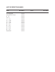
LIST OF EFFECTIVE PAGES Pages Cover/Copyright History/Effective Pages iii — vii viii — ix 1-1 — 1-6 2-1 — 2-20 3-1 — 3-21 4-1 — 4-44 A-1 — A-3 B-1 — B-2 C-1 — C-2 D-1 — D-2 E-1 — E-2 Registration Description Second Second Second Second Second Second Second Second Second Second Second Second Second Second Pages Description
Contents PREFACE CHAPTER 1 TIWAY I OVERVIEW 1.1 TIWAY I FEATURES . . . . . . . . . . . . . . . . . . . . . . . . . . . . . . . . . . . . . . . . . . . . . . . . . . . . . . . . . . . . 1-1 1.2 TIWAY I OPTIONS . . . . . . . . . . . . . . . . . . . . . . . . . . . . . . . . . . . . . . . . . . . . . . . . . . . . . . . . . . . . 1-2 1.3 SYSTEM BLOCK DIAGRAM . . . . . . . . . . . . . . . . . . . . . . . . . . . . . . . . . . . . . . . . . . . . . . . . . . . . 1-2 1.
3.4 INSERTING THE MODULE INTO THE BASE . . . . . . . . . . . . . . . . . . . . . . . . . . . . . . . . . . . . . . 3-12 3.5 NIM SWITCHES . . . . . . . . . . . . . . . . . . . . . . . . . . . . . . . . . . . . . . . . . . . . . . . . . . . . . . . . . . . . . 3-14 3.6 TI505 NIM DIAGNOSTICS . . . . . . . . . . . . . . . . . . . . . . . . . . . . . . . . . . . . . . . . . . . . . . . . . . . . 3-16 3.7 MODULE LOGIN VERIFICATION . . . . . . . . . . . . . . . . . . . . . . . . . . . . . . . . . . . . . .
APPENDIX A PM550 CIM REQUIREMENTS . . . . . . . . . . . . . . . . . . . . . . . . . . . . . . . . . . A-1 A.1 INTRODUCTION . . . . . . . . . . . . . . . . . . . . . . . . . . . . . . . . . . . . . . . . . . . . . . . . . . . . . . . . . . . . . A-1 A.2 LOCAL LINE LENGTH . . . . . . . . . . . . . . . . . . . . . . . . . . . . . . . . . . . . . . . . . . . . . . . . . . . . . . . . . A-1 A.3 LOCAL LINE BIAS AND TERMINATION . . . . . . . . . . . . . . . . . . . . . . . . . . . . . . . . . . . . . . . . .
List of Figures 1-1 1-2 TIWAY I System Block Diagram . . . . . . . . . . . . . . . . . . . . . . . . . . . . . . . . . . . . . . . . . . . . . . . . 1-3 NIM Simplified Block Diagram . . . . . . . . . . . . . . . . . . . . . . . . . . . . . . . . . . . . . . . . . . . . . . . . . 1-6 2-1 2-2 2-3 2-4 2-5 Number of Local Line Secondaries versus Cable Length . . . . . . . . . . . . . . . . . . . . . . . . 2-9 TIWAY I Tap Housing . . . . . . . . . . . . . . . . . . . . . . . . . . . . . . . . . . . . . . . .
List of Tables 2-1 2-2 RS-232-C Connections . . . . . . . . . . . . . . . . . . . . . . . . . . . . . . . . . . . . . . . . . . . . . . . . . . . . . . . 2-4 Pin Assignments for Local Line Connectors . . . . . . . . . . . . . . . . . . . . . . . . . . . . . . . . . . . . 2-7 3-1 3-2 3-3 TI505 Component Power Requirements . . . . . . . . . . . . . . . . . . . . . . . . . . . . . . . . . . . . . . . 3-2 Network Address Selection . . . . . . . . . . . . . . . . . . . . . . . . . . . . . . . . . . . . . . .
Preface MANUAL OVERVIEW This manual contains the information necessary to install and operate the SIMATIC TI505 Network Interface Module (NIM). The following information is provided.
APPENDIX D — SPECIFICATIONS provides general specifications for the TI505 NIM APPENDIX E — PRIMITIVE EXAMPLES provides a simple primitive example in normal and extended addressing modes. RELATED PUBLICATIONS The following publications contain additional information on TIWAY I and TIWAY I compatible products. To order these publications, contact your Siemens Industrial Automation, Inc. distributor or sales office.
Chapter 1 TIWAY 1 Overview 1.1 TIWAY I FEATURES TIWAY I is an industrial Local Area Network (LAN) designed to satisfy today’s factory and plant requirements for data acquisition and control of manufacturing processes. It is a significant enhancement of the Siemens “Local Line,” which supports the PM550 Programmable Controllers (P/Cs) and DS 990 computer products. The TIWAY I network provides a reliable and flexible communication architecture.
1.1 TIWAY I OPTIONS TIWAY I network products provide a number of options. 1.2 TIWAY I networks can be configured for short distances or a long distances. Redundant or single media transmission is available. Baud rates from 110 baud to 115.2K baud are available. TIWAY I devices can operate with modems in either full or half duplex mode, synchronously or asynchronously. Both NRZ and NRZI data encoding are available.
1.3 TIWAY I UNIVERSAL COMMAND LANGUAGE, UCL TIWAY I provides a Universal Command Language for all communication on the network. The UCL consists of a set of high-level request/response transactions known as Primitives. Primitives are used for: Reading and writing data Acquiring status of devices attached to the network Performing control operations on attached devices The Host issues requests (Primitives) to the NIMs and Secondary Adapters.
1.4 THE TI505 NIM The TI505 NIM is the TIWAY I Network Interface Module for the SIMATIC TI505 Programmable Controllers. See Chapter 3 for a specific listing of controllers supported by the TI505 NIM. The TI505 NIM provides several features which ensure maximum network signal integrity. 1-4 Each communication port is provided with a “Jabberstop” circuit to disable the port’s transmitter in the event of a communication port failure.
The TI505 NIM provides redundant TIWAY I communication ports. Each of the following models supports a specific type of network communication media. PPX: Number Port A Port B PPX:505-7339 PPX:505-7340 Local Line RSĆ232ĆC/423 Local Line RSĆ232ĆC/423 The RS-232-C/423 media interface is configured as Data Terminal Equipment (DTE) and is used to connect the NIM to Data Communication Equipment (DCE) for operation with modems.
Figure 2 is a simplified block diagram of the TI505 NIM. The media interface blocks are intentionally left unlabeled because the type of media interface depends on which NIM model you are using. The blocks are described as follows. Special Function Interface Controller (SFIC) — delivers and receives P/C communications. NIM controller — translates the communication (between Primitives and the P/C communication language).
Chapter 2 Network Design Considerations 2.1 TIWAY I NETWORK CONFIGURATION TIWAY I is a multi-drop communication network which consists of a main trunk cable (the “spine”) and dropline cables. The network can connect up to 254 secondaries (e.g., TI505 P/Cs) to a host computer. The TI505 NIM provides the interface to the network host, enabling the host and the P/C to communicate with each other. Also included with this manual is a “TIWAY I Network Configuration Data Sheet” (Appendix B).
2.1.1 Communication Media The following signal-transmission media are supported by TIWAY I: RS-232-C/423 dedicated lease-line modem interface in which no dial-up is necessary, providing extended (cross-continental) geographic coverage. RF or short-haul modem link-ups (cross-plant or cross-town coverage). Siemens Local Line (up to 25,000 feet). NOTE TIWAY I does not directly support dial-up modems which require Modem Control Commands for communication switchover.
The selection of the network communication media depends primarily on the geographic distance to be spanned. The main TIWAY I trunk can be up to 10,000 feet long (25,000 feet depending on system loading and baud rate selection), and can have up to 254 droplines. Each dropline can be up to 100 feet long. For distances exceeding 25,000 feet, RS-232-C/423 media interfaces and modems should be used. NOTE The proper installation of your communication media requires careful planning and design.
2.2 RS-232-C CABLE INSTALLATION The physical layer in TIWAY I provides a modem interface for synchronous or asynchronous modems at data transmission rates up to 115.2K bits per second. 2.2.1 RS-232-C Connections The modem interface provides standard signals, as defined in Table 2Table 3 for control of two-way alternate data transmission using both half and full duplex modems.The modem interface is a standard “Type E” DTE configuration as defined in Section 5 of EIA RS-232-C.
2.2.2 RS-232-C Timing Considerations If you use the TI505 NIM with a dedicated short-haul RF modem, the NIM has a one-second time-out between the transmission of its RS-232-C Request to Send (RTS) and the RS-232-C Clear to Send (CTS) response. This time-out value is set at one second to enable the RF device to switch from receive to transmit without losing access to the transmission media. NOTE This extended time-out feature is an important consideration when selecting a TIWAY I-compatible RF Modem.
2.3 LOCAL LINE CABLE INSTALLATION The following paragraphs describe Local Line characteristics and installation guidelines. 2.3.1 Local Line Characteristics The TIWAY I Local Line is a physical signaling technique (baseband, differential current drive) which operates over shielded, twisted-pair cabling. The Local Line cable may be up to 25,000 feet long, depending on loading and baud rate selection. It uses tap housings to simplify the addition of network connections.
The interface cable should have a male, 9-pin D-type receptacle with pin assignments as shown in Table 4.
2.3.2 Local Line Cable The TIWAY I local line network cable consists of a main cable or spine with droplines or taps for each Secondary. Interrelated network variables having direct influence on network performance are: Maximum trunk cable length Cable type Tap length Tap spacing Number of secondaries Maximum baud rates Siemens recommends Belden 9860 twisted pair cabling, or its equivalent, for use as the Local Line network spine.
Figure 1 illustrates the relationship of cable distance to the number of secondaries for different baud rates for two types of twisted pair cable. Note that the cable distance (in thousands of feet) is shown vertically; the maximum number of units that may be attached is shown horizontally.
2.3.3 Local Line Tap Housings The tap housing, shown in Figure 2, is made by Siemens specifically for its Local Line network. The tap housing can be mounted rigidly to a NEMA panel or other enclosure. It can also be used to splice cables in a cable tray without being rigidly mounted. The tap housing not only allows an orderly connection to the TIWAY I network, but also contains terminating resistors, resists moisture, relieves strain, and provides noise isolation for attached cabling.
With the cover removed from the PPX:500–5606 Tap Housing, note that there are three sets of terminals, and that each set is labeled G (Ground), W (White), and B (Blue). (See Figure 2Figure 2.) One set of these terminals is for the incoming Local Line twisted pair; the center set is for the drop line; and the remaining set is used to connect the Local Line to the following node, or to terminate the Local Line if the tap housing is the last one on the network trunk.
2.3.4 Planning Considerations Some major points to consider during the planning phase of a Local Line network are as follows: 2.3.5 From the start, allow for system growth. This means making provisions for the attachment of additional computing devices by routing cables through all probable areas of future plant expansion. Always make the network flexible enough to allow for re-arrangement of plant equipment.
Figure 3 Tap Spacing Examples TIWAY 1 Ti505 NIM User Manual Network Design Considerations 2-13
2.3.6 Cable Routing Cable routing should be planned as if the path between all stations on the network were free of obstructions. Next, modify the first routing to account for obstructions, then calculate the amount of cable needed. CAUTION All local and national electrical codes and fire codes should be observed when installing wiring.
In-ceiling cable networks are not always practical. In-ceiling installations can be difficult and sometimes dangerous in areas without drop ceilings (or that have unusually high ceilings). Also, closed ceiling systems usually trap dust and other debris, which makes cable maintenance difficult. 2.3.6.3 Surface Duct Routing Surface ducting for network cabling is usually installed along the baseboards or is attached to walls at desktop height.
2.4 LOCAL LINE BIASING In certain network configurations, the Local Line must be biased to raise its noise immunity and to prevent oscillations of receivers connected to the line. The need to apply a bias voltage to the Local Line depends on the interface configuration of your network. 2.4.1 Biasing Configurations It is very likely that you will have a mixture of TI505, SIMATIC TI500, and PM550 P/Cs on your network.
2.4.2 Networks with only Self-biased Devices This configuration exists when all TIWAY I Devices on the network are self-biasing (i.e., they do not have a Bias Switch.) In this case, the position on the line of the interface devices does not matter. 2.4.3 Networks with a Single Switch-biased Device This configuration exists when only one TIWAY I Device on the Local Line has the Bias Switch, and all other devices are self-biasing.
2.4.4 Networks with Two or More Switch-biased Devices This configuration exists when multiple switch-biased TIWAY I Devices are attached to the network, and they should be positioned as described in the following paragraphs. If two or more devices having the Bias Switch are attached, place one at each end of the Local Line, and turn on each Bias Switch. All other devices having a Bias Switch can then be placed anywhere on the network, with the Bias Switches turned off for the port being used. See Figure 4.
2.4.5 Terminating the Local Line The TIWAY I Local Line is designed to operate with shielded, twisted-pair cable which has a characteristic impedance of 124 ohms. In all configurations, the Local Line must be properly terminated at both ends of the trunk to prevent an impedance mismatch which could result in signal reflections on the line. Termination is required regardless of the number or type of devices attached to the network.
NETWORK CABLE INPUT OUTPUT G G B W W G B TERMINATION RESISTORS 68 ohms 5% 1/4 WATT W B CABLE TO MODULE Figure 5 Terminating the Local Line NOTE All Siemens tap housings contain factory-installed terminating resistors. If the tap housing is not used to terminate the Local Line, the terminating resistors must be removed when the output cable is attached.
Chapter 3 Installation 3.1 GENERAL REQUIREMENTS The following requirements must be met in order to install and use a TI505 NIM: 1. The appropriate NIM should be selected. PPX:505–7339 (Redundant Local Line) PPX:505–7340 (Redundant RS-232-C) 2. The TI505 NIM must be used with a model SIMATIC TI525 or SIMATIC TI535 P/C. For full NIM capabilities, the P/C software release level should be greater than (or equal to) the following releases. TI525 TI535 Release 2.2 Release 1.
Table 1 TI505 Component Power Requirements Power Available (in watts) +5 V –5 V PPX:505–6660 Power Supply PPX: Number 3-2 Installation 55 Description 3.75 DC Power Required (in watts) +5 V –5 V PPX:505–6830 IOCC 5.0 0.1 PPX:505–6840 Distributed Base Controller 5.0 0.1 PPX:505–4008 24 VAC Input (8 point) 2.0 — PPX:505–4016 24 VAC Input (16 point) 2.0 — PPX:505–4032 24 VAC Input (32 point) 2.0 — PPX:505–4108 LVDC/TTL Input (8 point) 2.
Table 1 TI505 Component Power Requirements (Continued) PPX: Number Description DC Power Required (in watts) +5 V –5 V PPX:505–4508 24 VDC Output (8 point) 2.5 — PPX:505–4516 24 VDC Output (16 point) 2.5 — PPX:505–4532 24 VDC Output (32 point) 2.5 — PPX:505–4608 110 VAC Output (8 point) 2.5 — PPX:505–4616 110 VAC Output (16 point) 2.5 — PPX:505–4632 110 VAC Output (32 point) 2.5 — PPX:505–4708 24 VDC Output (8 point) 5.0 — PPX:505–4716 24 VDC Output (16 point) 5.
3.2 INSTALLING THE NIM To place a NIM into your TI505 system, you have to select the NIM communication parameters, install the NIM in the TI505 I/O base, connect the communication cables to the NIM, and initialize the system for operation. The Programmable Controller (P/C) and the programming device should be in place before you install a NIM.
3.3 SETTING THE DIPSWITCHES As Figure 1 illustrates, there are two blocks of dipswitches on the TI505 NIM. The block of eight switches is the NIM Network Address Selection switch. The block of ten switches is the Network Configuration Parameters switch. Note that the switches are numbered from left to right (when the switches are facing you). When setting up your NIM, use the configuration data sheet in Appendix B of this manual to record important configuration information.
Figure 2 provides a summary of the dipswitch settings. The following paragraphs provide detailed information about the parameters selected by each switch. Network Configuration Parameters 0, CLOSED, ON 1, OPEN, OFF Transmit delay inactive Transmit delay active Lockout disabled Lockout enabled NRZ encoding NRZI encoding HDLC protocol X.
3.3.1 Selecting the Network Address Each TIWAY I Network Secondary must have a unique binary network address. The range of valid addresses is 1 to 254 (0000 0001 to 1111 1110 on switches 1–8 of the Network Address Selection dipswitch). Selecting addresses 0 or 255 (0000 0000 or 1111 1111) on the Network Address Selection dipswitch will cause the NIM to initialize in a test mode, and the NIM will fail to operate properly.
3.3.2.1 Data Transmission Rate Network Configuration Parameter switches 1 through 4 select the data transmission rate. All devices on the network must be configured to communicate at the same data rate. The data rates corresponding to the switch settings are shown in Table 3. For synchronous operation in RS-232-C communication, the rate of data transmission is established by the modem. When setting switches one through four, select a data rate which matches that of the modem exactly.
3.3.2.2 Synchronous / Asynchronous Selection Network Configuration Parameter switch 5 selects synchronous or asynchronous operation for modems. For synchronous modem communication, the NIM receives the transmit and receive timing signals from the modem via transmit signal timing element (DB), and receive signal timing element (DD). If the modem data rate does not match the TIWAY data rate exactly, the data rate select switches should be set to a rate that is the next lower data rate from the modem.
3.3.2.4 X.25 / HDLC Network Configuration Parameter switch 7 selects the communication protocol. The HDLC protocol is activated when the switch is closed, or positioned towards the top of the dipswitch. The X.25 protocol is only activated when this switch is set open, or positioned towards the bottom of the dipswitch. The X.25 protocol is not used with the TIWAY I or UNILINK Host Adapter, although it is an option when communicating with any Primary supporting this protocol. 3.3.2.
3.3.2.6 Lockout / Enable Network Configuration Parameter switch 9 enables the P/C to “lockout” the NIM during time-critical operations. This function is not needed normally. During lockout, the NIM will not communicate with the P/C. The actual mechanism is as follows: 1. The P/C “sees” the NIM as an 8 channel discrete output module on the I/O portion of the scan. 2.
3.4 INSERTING THE MODULE INTO THE BASE It is advisable to install the NIM in the slot adjacent to the CPU (Central Processing Unit). This provides the following advantages. Easier access to switches and connectors Better LED indicator visibility Reduced electrical noise susceptibility To avoid causing electrostatic damage to the Printed Circuit Board (PCB) components, do not touch the PCB while inserting the module into the base.
Figure 3 Installing the NIM in the I/O Base TIWAY 1 Ti505 NIM User Manual Installation 3-13
3.5 NIM SWITCHES There are three switches located under the hinged switch cover. These switches, which are shown in Figure 3Figure 4, are labeled RESET, TEST and LOCAL/REMOTE.
3.5.1 Reset This switch is a momentary contact switch which resets the NIM and initiates the power-up diagnostics. This switch causes all indicators to be on for approximately 1 second. Then all indicators, with the exception of the TEST indicator, are extinguished for approximately 10 seconds. During this time, the NIM runs a series of diagnostic tests to verify the hardware components of the NIM. A successful completion of these tests will leave only the NIM GOOD and PC GOOD indicators on.
3.6 TI505 NIM DIAGNOSTICS There are three levels of TI505 NIM diagnostics available. Power-up diagnostics Run time diagnostics User-initiated diagnostics The TI505 NIM has six LED indicators that are used extensively during the diagnostics. The indicators, located above the switch cover, are shown in Figure 3Figure 5.
3.6.1 Power-Up Diagnostics The TI505 NIM executes the power-up diagnostics in the following cases: Immediately following the application of +5VDC from the I/O base (power-up) as part of its initialization Any time the Reset switch is pressed Following an HDLC DISC command from the Primary (A UNILINK Adapter can be configured to disallow the disconnect command. See the UNILINK Host Adapter User’s Manual for additional information.
3.6.2 Run Time Diagnostics The TI505 NIM monitors itself continuously during normal operation, as follows: The Operating System continuously performs a ROM integrity test as a background operation. The NIM periodically verifies that it is capable of communicating with the TI505 P/C. A Watchdog Timer circuit in the NIM helps protect against software lockup. Failures detected in the ROM integrity test will cause the NIM GOOD LED to extinguish, and force the NIM into a failed state.
3.6.3 User-Initiated Diagnostics You can initiate a complete test of the NIM hardware, including the communication ports. Complete the following steps to start the NIM diagnostics. CAUTION Since this test includes the communication ports, it is necessary that the NIM be disconnected from the TIWAY network. 1. Disconnect network cables from both NIM network ports. 2. Install loopback connectors (part no. 2641307–0001) on the NIM RS-232-C port(s). 3.
If the NIM fails the test, the following conditions apply. 1. If the NIM GOOD LED indicator is extinguished, then an internal NIM failure was detected. 2. If the PC GOOD LED indicator is extinguished, then a problem was found in attempting to communicate with a TI505 P/C. 3. If the XMT LED indicator is extinguished, a failure was detected on the bottom port (Port B). This could be due to a missing loopback connector. 4.
3.7 MODULE LOGIN VERIFICATION After the NIM has been installed and configured, you should verify that the NIM is logged into the P/C I/O map. (This is the first thing you should do if the PC GOOD LED is not lit.) Connect a programming device to the P/C to verify P/C-module communication. If you have a TI525 P/C system with a Video Programming Unit (or a SIMATIC TISOFT package), press F3 for the CONFIO function, then F2 for SHOW, and then F7 for READ BASE.
Chapter 4 NIM Primitives 4.1 OVERVIEW Primitives are high-level commands that allow a user to access like data types in all different Secondaries in the same manner. For example, a host computer can access image register memory in several different models of TI P/Cs with the same command. The Primitives remove as many differences as possible between the P/Cs, so that applications programs at the Primary (host) level may treat all TIWAY I Secondaries in the same manner. Primitives provide several benefits.
4.2 PURPOSE Primitives serve as the command structure that a TIWAY I Primary uses to access (read or write) information in a TIWAY I Secondary. The Primitives defined in the following paragraphs serve these basic functional needs. 4.
Figure 1 illustrates the basic Primitive structure when HDLC operation is selected. There is a Request Format and a Response Format, as shown. The binary weight of the fields is detailed in Figure 2. All field lengths are multiples of 8 bits, which allows for octet testing of data link frames at the data link/media access control layer.
First Transmitted Bit F I E L D Least Significant Bit Most Significant Bit Figure 2 Binary Weight of the Fields 4.3.1 Normal Operation and Exceptions Normal Primitive operation consists of a request and response sequence without exceptions. Exceptions are errors found in the interpretation or execution of a Primitive. The normal operation of a Primitive is for the initiating (Host) station to form a request Primitive and address it to a Secondary on the network.
An exception procedure is used when the addressed device finds fault with: The value of the Length field A Primitive format A data element type The execution of a Primitive If a fault is found with the Length field, Primitive format, data element type or in the execution of the Primitive, the exception reason is returned with the Exception Primitive, which is Primitive Code 00. 4.3.
4.4 LOGICAL GROUPS All Seimens’ TIWAY Primitives fall into logical groups according to their function, as shown in Table 1. The TIWAY I Primitive subset is taken from the categories listed in Table 1.
The subset of TIWAY I Primitives supported by the Series 505 NIM is given in Table 2. Future additions to this subset will be announced as they are implemented. Note that each of the following Primitives fits into the general categories listed in Table 1.
4.5 FIELD DEFINITIONS The basic Primitive Request and Response field formats are shown in Figure 3. Each of the basic field types shown is described in the following paragraphs.
4.5.1 Field Symbols The symbols used in the remainder of this section to denote the different types of Primitive fields are summarized in Table 3. The length of the field (in bytes) is represented by the number of characters in the field symbol. A byte is represented by two symbols. For example, the field LLLL is a two-byte (16 bit) field. Field symbols with “. . .” are variable length fields. Table 3 Summary of Primitive Field Symbols 4.5.
4.5.3 Primitive Code Field – PP The Primitive Code Field is eight bits long, which allows for 256 unique Primitives. The most significant bit of the Primitive field code designates whether extended addressing is in effect. If extended addressing is used, the data element location descriptor is a 32-bit field rather than the 16-bit field associated with non-extended addressing.
Data Element Location — Data element types are accessed by a location address, designated by “AAAA” or “AAAA AAAA”. In the Series 505 NIM, the location descriptor is a 16-bit value (32 bits if extended addressing is used in the Primitive code field). The allowable values for the data element location are from 1 to the maximum values shown in Table 5. For TT Type 12 (Drum Count Preset) the format changes slightly.
4.6 DATA ELEMENT TYPES AND FORMATS The data element types (TTs) and their length (in bytes) are defined in Table 4. Figure 4 through Figure 8 show the format of the data elements.
TT = 3, 4, 5 = Discrete (1 byte) 1 MSB 2 0 0 3 4 5 0 0 0 X value 6 7 0 8 0 LSB X Bit Definition 0 1 Off On Figure 4 Discrete Data Element Format TT = 6, 7, 8 = Packed discrete (1 byte) 1 2 3 4 5 6 7 MSB 8 LSB Next sequential discrete bit accessed. First discrete bit number accessed. Value 0 1 Bit Definition Off On If the number of packed discrete bits requested is not an even multiple of eight, the unused positions are set to zero.
TT = D = Word force (3 bytes) MM where, MM is the forced state or forced action to take MM value 00* 01 FF** Force state / action Unforced Forced Unforce * If used in a Write Primitive, it can only write to an unforced word. It will not unforce a word, but it will change the word value ** Used only in Write Primitives to unforce a word. It does not have a DDDD value and the data length is 1 byte instead of 3 bytes.
TT = B, Discrete Force (1 byte) C, CR Force (1 byte) DD Value Discrete Value Force State 00 Off Unforced 01 On Unforced 80 Off Force 81 On Force FF — Unforce* Used only in a Write Primitive, unforces a forced data element location, but does not change the value Figure 7 Forced Discrete and CR Data Element Format TT = 17 = Secondary System Status (2 words)* MSB Word #1: ABCD LSB EFGH IJKL MNOP Each bit set to 1 indicates that the corresponding bit in word 2 is a reported status.
4.7 DATA ELEMENT LOCATION RANGES The maximum data element locations (AAAA field) for each data element type / P/C combination are provided in Table 5. For all the ranges in the table, the first legal value is 1; not zero. Values of zero are not supported.
Table 5 Data Element Location Ranges P/C Type Data Type PPX:525– PPX:525– PPX:525– PPX:525– PPX:535– PPX:535– 1102 1104 1208 1212 1204 1212 L Instruction TT = 00 2048 4096 8192 12000 4096 12000 V Variable TT = 01 1024 2048 4096 5120 2048 5120 K Constant TT = 02 0 0 0 0 0 0 1023 1023 1023 1023 1023 1023 Control Register CR, CR Packed TT = 5,8 511 511 511 1023 511 1023 Word I/O WX, WY TT = 9,A 1023 1023 1023 1023 1023 1023 Discrete Force TT = 0B 1023 1023 1023 10
4.8 DATA FIELD LENGTH RESTRICTIONS Table 6 and Table 7 provide the maximum number of bytes that can be gathered or written for Read and Write Primitives. Table 6 Maximum Read Primitive Data Byte Length Read Primitive 20 21 51 52 56 57 Maximum number of bytes read per Primitive request.
Table 7 Maximum Write Primitive Data Byte Length Write Primitive Maximum number of bytes that may be written per Primitive request. (When using extended address) * 30 31 52 57 267 265* 263 265** 265 263* 261 263** Consult Table 4Table 4 for the number in each data element, and Table 4Table 5 for the maximum available data element address. This number assumes that only one data block is requested.
4.9 SERIES 505 NIM PRIMITIVE DESCRIPTIONS The following paragraphs describe the NIM Primitives used in the Series 505 NIM. Refer to Table 2 for a complete list of the Primitives supported.
4.9.1 Exception Primitive – Code 00 Primitive 00 returns the error status from a Secondary. For example, if a Primary tries to read variable memory at location 0000 in a Series 505 NIM, a Primitive 00 response would indicate that the memory address was out of range with an exception field of 0002. Request: There is no request defined for this Primitive.
Symbol Value Definition DDDD 17 Attached device did not respond properly 19 Resulting data element location formed by the starting address, plus the number of data element to access, is out of range specified by TT 1A Communication has not been established with the attached device 1B Store and forward buffer is full and the store and forward message was discarded 1C Data element field (specified by TT) is improperly formatted 1D Number of locations to access equals zero (NNNN = 0) 23 Number
4.9.2 Native Primitive – Code 01 The Native Primitive 01 allows access to an attached device by using a Task Code which is unique to the specific device addressed. By using Primitive 01, you can embed a P/Cunique Task Code and access anything in P/C memory, for example, that a VPU can access. Request: LLLL 01 DD. . .DD, where DDDD is the task code acceptable to the device being accessed. Response: LLLL 01 HH DD. . .
4.9.3 Status Primitive – Code 02 Primitive 02 is the Status Primitive. It reports the current operational state of the attached device and NIM in a common format for all types of attached devices. The NIM gets a status update from the attached device every 4 seconds.
4.9.4 Configuration Primitive – Code 03 Primitive 03 allows the Primary to identify the types of devices that exist on the network. For example, a Primitive 03 response from a TI525 P/C is different from a 5TI P/C response.
4.9.5 Primitive Format Configuration – Code 04 Primitive 04 is the Format Primitive that allows you to ascertain the maximum length (in bytes) of the Primitive acceptable to the Network Interface Module. Request: LLLL 04 Response: LLLL 04 NNNN MM EE FF GG BB ... BB Symbol Definition NNNN Primitive descriptor(s) and data unit(s) field length supported, in bytes (270 bytes is returned) MM Number of Data Acquisition Blocks supported by the NIM (For Primitives 50, 51, and 52, 32 is returned.
4.9.6 Packed Native Primitive – Code 05 Primitive 05 allows one or more device task codes to be executed. Execution is aborted and an exception response returned if an exception occurs during processing. If an exception occurs during execution of any native task code, the error results are returned in the packed native response in the same position as in a normal response. Execution continues in this situation. Native task codes concerning “store” and “forward” are not supported. Request: LLLL 05 CC DD ...
4.9.7 Change State Primitive – Code 10 This Primitive allows you to change the operational state of the attached device. For example, you may enter the Run or Program modes with this Primitive. NOTE Issuing this command to enter the non-execution of instruction data type will cause specific attached devices to turn off or freeze their output systems, depending on the device. For an explanation of the modes of operation for a specific P/C, refer to the manual for that particular programmable controller.
4.9.8 Read Block Primitive – Code 20 Primitive 20 is a command to read a single contiguous block of data in the attached device. Read Block will access contiguous data elements starting from a given data element location. Request: LLLL 20 TT NNNN AAAA Symbol Value Definition TT Data element type NNNN Number of locations AAAA Data element location Response: LLLL 20 HH DD ...
4.9.9 Read Random Block Primitive – Code 21 Primitive 21 is a command to read several random blocks of contiguous memory. NOTE Data will not be returned for the blocks that were in error. Request: LLLL 21 TT NNNN AAAA (repeated) Symbol Value Definition TT Data element type NNNN Number of locations AAAA Data element location Response: LLLL 21 HH XX BB DD ...
4.9.10 Write Block Primitive – Code 30 Primitive 30 is the Write Block Primitive, which will replace a contiguous block of data starting from a given data element location with the data specified in the request. Request: LLLL 30 TT AAAA DD ...
4.9.11 Write Random Block Primitive – Code 31 Primitive 31 replaces several blocks of contiguous data with the data included in the request. Request: LLLL 31 TT NNNN AAAA DD ... DD (repeated) Symbol Value Definition TT Data element type NNNN Number of locations AAAA Data element location DD Data Response: LLLL 31 HH XX BB ...
4.9.12 Block Data Acquisition Primitive Codes 50 51 52 The Block Data Acquisition Primitives allow predefined blocks of different data types to be accessed with a single Primitive without re-defining the blocks in each transaction. The Define Block Primitive (50) specifies the random blocks. The Gather Block Primitive (51) collects the data from specific blocks. The Write and Gather Block Primitive (52) combines these functions.
4.9.12.2 Gather Block Primitive – Code 51 The Gather Block Primitive specifies which blocks (as defined by the Define Block Primitive 50) will be read. The blocks are specified through a 32-bit mask (EEEEEEEE). Each bit position in the bit mask corresponds to a block that was defined with Primitive 50, Define Block. A bit set to 1 indicates that the block is to be returned. A bit set to 0 means that the block will not be returned.
4.9.12.3 Write and Gather Block Primitive – Code 52 The Write and Gather Block Primitive specifies which blocks (as defined with Define Block Primitive 50) will be read. It also allows a user to replace any contiguous data element locations. The blocks to gather are specified through a 32-bit mask (EEEEEEEE). In the bit mask position which corresponds to a block specified in the Define Block Primitive, a bit value of 1 indicates that the block is to be returned.
Request: LLLL 52 EEEEEEEE TT AAAA DD ... DD (repeated) where EEEEEEEE is a 32 bit field defining the blocks to gather. MSB LSB ... ... Block Number 1 (hex) Symbol Value Block Number 20 (hex) Definition TT Data element type for the write operation AAAA Data element location for the write operation DD Data for the write operation Response: LLLL 52 HH EEEEEEEE DD ...
4.9.13 Record Data Acquisition Primitive Codes 55 56 57 The Record Data Acquisition Primitives allow repetitive collection of multiple predefined blocks of data. The Define Record Primitive (55) allows multiple blocks of data to be defined as a single record. The Gather Record Primitive (56) collects the data blocks for the requested records. The Write and Gather Record Primitive (57) combines the functions of the Write Block Primitive (30) and the Gather Record Primitive (56).
4.9.13.1 Define Record Primitive – Code 55 The Define Record Primitive specifies up to 32 records with 32 blocks per record. The records are referenced by number, ranging from 1 (hex) to 20 (hex). A record, once defined, can be re-defined. A record may be restored to the initial state of “undefined” by specifying the number of Data type Definitions (DD – blocks) in the record as zero.
4.9.13.2 Gather Record Primitive – Code 56 The Gather Record Primitive specifies which records (as defined by the Define Record Primitive 55) will be read. The records are specified by record numbers from 1 (hex) to 20 (hex). The total number of bytes returned by the record(s) must not cause the response to exceed the maximum frame length. The Response Primitive will return the data associated with the requested records, in the same order as they were requested.
4.9.13.3 Write and Gather Record Primitive – Code 57 The Write and Gather Record Primitive specifies which records (as defined with Define Record Primitive 55) will be read. It also allows you to replace any contiguous data element locations. The Records are specified by record numbers from 1 to 20 (hex). The total number of bytes returned by the record(s) must not cause the response to exceed the maximum frame length. Following the record numbers are the descriptors associated with the write function.
Request: LLLL 57 XX CC TT AAAA DD ... DD (repeated XX times) Symbol Value Definition XX Number of records to gather CC Record numbers to gather TT Data element type to write AAAA Data element location to write DD Data to write. Maximum DD ranges may vary depending on the number of records specified for the read function. Response: LLLL 57 HH XX CC DD ...
4.9.14 Summary of Primitives Table 8 summarizes the Series 505 NIM Primitives. Table 8 Summary of Primitives Primitive Format Exception Request Response (None) LLLL 00 PP DDDD (TT) (Optional) Native Request Response LLLL 01 DD ... DD LLLL 01 HH DD ... DD Status Request Response LLLL 02 LLLL 02 HH EE FF Configuration Request Response Primitive Format Configuration Request Response LLLL 03 LLLL 03 HH DDDD EEEE FFFF GGGG IIII JJJJ KKKK KKKK LLLL 04 LLLL 04 NNNN MM EE FF GG BB ...
Table 8 Summary of Primitives (cont.) Primitive Write Random Block Define Block Format Request LLLL 31 TT NNNN AAAA DD ... DD (repeated) Response LLLL 31 HH XX BB (BB is repeated XX times) Request LLLL 50 CC TT NNNN AAAA Response LLLL 50 HH Request Response LLLL 51 EEEEEEEE LLLL 51 HH EEEEEEEE DD ... DD (repeated) Gather Block (repeated) Write and Gather Blocks Request Response LLLL 52 EEEEEEEE TT AAAA DD ... DD LLLL 52 HH EEEEEEEE DD ...
Table 9 summarizes the same Primitives listed in Table 8, but with extended addressing. Table 9 Summary of Primitives (extended addressing) Primitive Format Exception Request Response (None) LLLL 00 PP DDDD (TT) (Optional) Native Request Response LLLL 81 DD ... DD LLLL 81 HH DD ...
Table 9 Summary of Primitives (cont.) Primitive Write Random Block Format Request LLLL B1 TT NNNN AAAA AAAA DD ... DD (repeated) Response LLLL B1 HH XX BB (BB is repeated XX times) Request LLLL D0 CC TT NNNN AAAA AAAA Response LLLL D0 HH Gather Block Request Response LLLL D1 EEEEEEEE LLLL D1 HH EEEEEEEE DD ... DD (repeated) Write and Gather Blocks Request Response LLLL D2 EEEEEEEE TT AAAA AAAA DD ... DD LLLL D2 HH EEEEEEEE DD ...
Appendix A PM550 CIM Requirements A.1 INTRODUCTION This appendix discusses biasing and terminating the TIWAY I Local Line for network installations containing CIMs in addition to self-biased and switch-biased devices. A.2 LOCAL LINE LENGTH The PM550 CIM supports operation over the Local Line at distances up to 10,000 feet and 9600 baud. Advances in technology have provided line drivers and receivers that support Local Line operation up to 25,000 feet.
NOTE All Siemens tap housings contain factory-installed termination resistors. If the Tap Housing is not used to terminate the Local Line, the terminating resistors must be removed when the output cable is attached. A.3.1 Networks with Switch-biased Devices and CIMs On networks using devices with the bias switch, CIMs, and self-biased devices, a bias must be applied to the line using the switch-biased device as described in the previous section.
2. If more than one CIM is attached to a Local Line, place CIMs at the extreme ends of the Local Line trunk. Install the jumpers provided with the outermost CIMs in accordance with the instructions in the PM550 CIM User’s Manual, Manual Number PM550–1101154–4. This will apply the correct bias to the Local Line to prevent oscillations of the CIM receivers.
Appendix B Network Congfiguration Data Sheet Location Network Name Cable Diagram Reference GENERAL SPECIFICATIONS Media type Network Baud Rate Sync/Asynch Full/Half Duplex Encoding Modem Type NETWORK NODE SPECIFICATIONS Node Name Network Address Controller Type Serial Number Software Release Interface Type Serial Number Software Release TIWAY 1 TI505 NIM User Manual Network Configuration Data Sheet B-1
DATA DEFINITION TABLE Date Name or Identifier B-2 Data Type Network Configuration Data Sheet Starting Address Number of Record Elements Number Block Number Length (Bytes) TIWAY 1 TI505 NIM User Manual
TIWAY 1 TI505 NIM User Manual Network Configuration Data Sheet B-3
Appendix C Network Evaluation Form If you would like Seimens Industrial Automation, Inc. to evaluate your network requirements, complete and submit the Network Evaluation Form. Seimens Industrial Automation, Inc.’s, Technical Services group will analyze your requirements and provide you with a network design plan and quote.
TIWAY I NETWORK EVALUATION FORM *DATE OF REQUEST: ____/____/____ TI FSE: *CUSTOMER COMPANY: CONTACT NAME: ADDRESS: TELEPHONE: (_____) _________ – ______________________ *AED CONTACT NAME: ____________________________________________________________ PHONE: *ORIGINATOR OF REQUEST: *APPLICATION: *PROPOSED HOST COMPUTER: *PROGRAMMING LANGUAGE: *PLC MODELS INITIAL PLC QUALITY NUMBER OF WORDS XFRED * PM550– * TI 520– * TI 530– * 5TI– * TI 560– * TI 565– * * (FEET) *MAXIMUM DISTANCE FROM HOST TO FARTHEST P
Appendix D Specifications Environmental specifications: Operating Temperature 0 to 60 C (32 to 140 F) Storage Temperature –40 to 85 C (–40 to 185 F) Relative Humidity 5% to 95% noncondensing Vibration Sinusoidal Random IEC 68–2–6, Test Fc; 0.15 mm peak–to–peak, 10–57 Hz; 1.0g, 57–150 Hz NAVMAT P–9492 or IEC 68–2–34, Test Fdc with 0.
Communications: Data Rates 110; 150; 300; 600; 1,200; 2,400; 4,800; 9,600; 19,200; 38,400; 57,600; 115,200 bits per second. RS–232–C/423 Ports Configured as Data Terminal Equipment (DTE), synchronous or asynchronous operation, full or half duplex operation, NRZ or NRZI encoding. Local Line Ports Local Line Ports default to asynchronous, half duplex, with NRZI encoding.
Appendix E Primitive Examples The following TIWAY I Primitive example reads four words of variable memory from a Series 505 P/C, starting at memory location 100 (hex = 64). The format for the request follows: Request: LLLL 20 TT NNNN AAAA = 0006 20 01 0004 0064, where: LLLL (Length) = 0006 Primitive Code = 20 TT (Data Type) = 01 (V, variable memory) NNNN (Number of locations) = 0004 AAAA (Address, data element location) = 0064 Response: LLLL 20 HH DD ...
In this example, the same task is performed as in the above example, but with extended addressing. Command: LLLL A0 TT NNNN AAAA AAAA = 0008 A0 01 0004 0000 0064, where: LLLL (Length) = 0008 Primitive Code = A0 (extended address format for Primitive 20) TT (Data Type) = 01 (V, variable memory) NNNN (Number of locations) = 0004 AAAA AAAA (Address) = 0000 0064 Response: LLLL A0 HH DD ...
SIMATIC is a trademark of Siemens AG. Series 505, TIWAY, UNILINK, TISOFT, PM550, PM551, and 5TI are trademarks of Siemens Industrial Automation, Inc. TI, TI500, TI505, TI520, TI520C, TI525, TI530, TI530C, TI535, TI540, TI550, TI560, TI565, are trademarks of Texas Instruments Incorporated. DEC, PDP, and VAX are trademarks of Digital Equipment Corporation Belden is a registered trademark of Cooper Industries.
Customer Registration We would like to know what you think about our user manuals so that we can serve you better. How would you rate the quality of our manuals? Excellent Good Fair Poor Accuracy Organization Clarity Completeness Overall design Size Index Would you be interested in giving us more detailed comments about our manuals? Yes! Please send me a questionnaire. No. Thanks anyway.
FOLD NO POSTAGE NECESSARY IF MAILED IN THE UNITED STATES BUSINESS REPLY MAIL FIRST CLASS PERMIT NO.3 JOHNSON CITY, TN POSTAGE WILL BE PAID BY ADDRESSEE ATTN: Technical Communications M/S 3519 SIEMENS INDUSTRIAL AUTOMATION INC.