SIMATIC TIWAY 1 UNILINK Host Adapter User Manual Order Number: PPX:TIWAY–8121–2 Manual Assembly Number: 2587871–0045 Second Edition
CHAPTER 1 THE UNILINK HOST ADAPTER 1.1 INTRODUCTION The UNILINK Host Adapter, Figure 1–1 is a second generation host computer interface product that allows a host computer to operate and control secondary devices on a TIWAY I network. The UNILINK Host Adapter, also referred to as the “adapter” in this manual, is a hardware and software extension of the original TIWAY I Host Adapter.
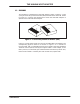
THE UNILINK HOST ADAPTER 1.2 FEATURES The hardware is composed of the UNILINK Adapter, shown in Figure 1–1, with a plug-in Personality Interface Module (PIM) PPX:500–6224. The PIM, shown in Figure 1–2, contains the software that causes the UNILINK Adapter to operate as the UNILINK Host Adapter. Figure 1–2 Personality Interface Module (PIM) Figure 1–3 illustrates the basic structure of the UNILINK Host Adapter. The corresponding physical features are shown in Figure 1–4.
THE UNILINK HOST ADAPTER Host Computer RS–232–C/RS–423A Host Interface (Command Processor) TIWAY I Interface UniLink Host Adapter External Input Point Output Point TIWAY I Network Secondaries Figure 1–3 UNILINK Host Adapter Block Diagram Host Computer Port Port 1 Port 2 Port 3 Power Connections Port 4 AC AC GND NEUT LINE I/O 12345 TIWAY I Ports External I/O Points PPX:500–7111, Dual Local Line media ports shown here.
THE UNILINK HOST ADAPTER The features of the UNILINK Host Adapter include: The adapter is noise hardened for factory floor use. There are internal diagnostics tests to check the internal operation when powered-up or reset, and during normal operation. There is also a selectable test mode that is set locally. The adapter can be reset locally with an internal switch or remotely with a host issued command.
THE UNILINK HOST ADAPTER 1.3 The adapter is configurable for a variety of applications needs and includes multiple host computer support, allowing several host computers to communicate with the secondary devices on the same TIWAY I network. The adapter provides transaction statistics collection to aid network performance tuning. TYPICAL NETWORK APPLICATIONS Figure 1–5 illustrates a typical single host network managing a process control application.
THE UNILINK HOST ADAPTER The flexibility of the UNILINK Host Adapter also provides for multiple hosts as illustrated in Figure 1–6. In addition to the process control application, your main plant system can link to the same network to track work-in-progress, adjust schedule loads for peak efficiency, and collect product cost data. With an additional UNILINK Host Adapter, you can also add a personal computer workstation to the network for statistical quality control or other uses.
THE UNILINK HOST ADAPTER 1.4 TIWAY I SYSTEM CHARACTERISTICS TIWAY I is a bus structure Local Area Network (LAN) designed for industrial environments. The TIWAY I network connects a series of Texas Instruments Programmable Controllers (P/Cs) and other devices to one or more host computers.
THE UNILINK HOST ADAPTER With appropriate host software, an operator can program, monitor, and control any P/C or other intelligent device on the TIWAY I network from a single location. The importance of the UNILINK Host Adapter is that it provides a communication link between the TIWAY I network and one or more host computers. Figure 1–7 is a diagram representing the various host computers that can be connected to a UNILINK Host Adapter, and the typical devices that can be controlled in a TIWAY I network.
THE UNILINK HOST ADAPTER 1.5 INSTALLATION Instructions for installing the UNILINK Adapter and the UNILINK Host Adapter PIM are given in the UNILINK Adapter Installation and Operation Manual (PPX:TIWAY–8106). It provides the electrical and mechanical installation instructions and guidelines for the the UNILINK Host Adapter. Chapter 2 discusses the different operational modes and how they are configured.
CHAPTER 2 OPERATION AND APPLICATION 2.1 INTRODUCTION This chapter provides an introduction to the UNILINK Host Adapter operation and how it can be used in typical applications. You should refer to Chapter 5 for the complete command syntax and to the Glossary for help with any unfamiliar terms. Network planning forms are located in Appendix E, Appendix F, and Appendix G. 2.2 COMMAND PROCESSING The UNILINK Host Adapter commands are a set of functional tools to help you direct network applications.
OPERATION AND APPLICATION Network Manager Commands Performance and Applications Flexibility Extended HIU Commands Configure Adapter Commands Mode Independent Commands Basic HIU Commands Figure 2–2 NUMBER OF COMMANDS Performance vs Commands Communications between the host computer and the UNILINK Host Adapter are a series of commands and responses as illustrated in Figure 2–3. For every command sent, there will be a response. The response will be one of the following.
OPERATION AND APPLICATION Host Computer Secondary Commands UNILINK Host Adapter Responses Secondary Figure 2–3 Host Computer To UNILINK Host Adapter Communications Commands are checked for errors before they are executed. The ERROR RESPONSE is a special response that returns a code indicating the type of error. If an error is found, the command will not be executed and the ERROR RESPONSE will be returned.
OPERATION AND APPLICATION 2.3 FUNCTIONAL ORGANIZATION AND OPERATING MODES The UNILINK Host Adapter is organized into two primary functions; the Host Interface Unit (HIU) function and the Network Manager (NM) function. An adapter can be configured with one of these functions or they can be combined to form a Master Host Interface Unit (MHIU). The MHIU, HIU, and NM are three of the six configurable operating modes.
OPERATION AND APPLICATION HIU Establishes communications between the host computer and the secondary devices. Uses memory for: Macro Buffers (Dynamically allocated) Host–to–Secondary Statistics Figure 2–4 Host Interface Unit Function Part of the statistics memory area is used for a Secondary Log. As commands are issued to connect and disconnect secondaries, the specified secondary address is added or deleted from the Secondary Log and a network request is queued into the Network Manager.
OPERATION AND APPLICATION 2.3.2 Network Manager Function Acting as the network primary, the Network Manager function is responsible for controlling the message traffic on the TIWAY I network as shown in Figure 2–5. It receives the requests from HIUs and stores them in a NM buffer, routes them to the designated secondary devices, and returns the secondary response to the HIU that issued the request. There can be only one adapter configured with the Network Manager function in any particular TIWAY I network.
OPERATION AND APPLICATION The following operational modes include the NM function. However, the MHIU/EHA mode does not provide access to the NM command set. 2.3.3 Master Host Interface Unit (MHIU) Network Manager (NM) Standalone Network Manager (SANM) Master Host Interface Unit/Emulate Host Adapter (MHIU/EHA) The Master Host Interface Unit Mode The Master Host Interface Unit (MHIU) is a combination of the HIU and NM functions as shown in Figure 2–6.
OPERATION AND APPLICATION 2.3.4 Typical Network Applications Both single and multiple host networks are supported by the UNILINK Host Adapter. Figure 2–7 illustrates a typical single host network which uses an MHIU as the host interface and network manager.
OPERATION AND APPLICATION Host Computer Host Computer UNILINK UNILINK UniLink Host Adapter (MHU) UniLink Host Adapter (MHU) Figure 2–8 Typical Multiple Host Network Host Computer Host Computer UNILINK Host Computer (HIU) UNILINK (HIU) UNILINK Figure 2–9 NM Network 2–9 UNILINK HOST ADAPTER USER MANUAL
OPERATION AND APPLICATION 2.3.5 The Emulate Host Adapter Modes There are two modes available that provide an emulation of the TIWAY I Host Adapter; the MHIU/EHA and the HIU/EHA. These modes are limited to the base command codes 01 through 08, 20, 21, and FC through FF. The POLL command, code 03, is not available in the HIU/EHA mode. Both of these modes will operate with applications software written for the TIWAY I Host Adapter.
OPERATION AND APPLICATION TIWAY I Host Software can be used with adapters in a multiple host network. However, you must define an HIU address using the XPAR subroutine and the CONFIGURE HIU command, and you cannot use the POLL command.
OPERATION AND APPLICATION 2.5 SETTING THE OPERATING MODE Each adapter must be configured for one of the six possible operating modes. The mode is configured with the CONFIGURE ADAPTER command with the exception of the Standalone NM mode, which is chosen by setting Positions 9 and 10 of Dipswitch 1 down. The defaults and dipswitch settings are discussed further in Paragraph 2.5.1. There are three configuration commands; the CONFIGURE ADAPTER command, the CONFIGURE HIU command, and the CONFIGURE NM command.
OPERATION AND APPLICATION operating mode to the value specified. The only operating mode that can not be set with this command is the Standalone Network Manager (SANM), since it can not accept any host computer commands. Instead, the SANM mode is selected by dipswitch settings described in Chapter 3 and Chapter 4. Each host computer must send this command to its attached UNILINK Host Adapter(s). The mode remains in effect and can not be changed until the adapter is reset.
OPERATION AND APPLICATION At any time, your applications software can retrieve the current values for these parameters by issuing the REPORT ADAPTER CONFIGURATION command, code 21. In addition to those parameter values, this command will also return the values of the dipswitch settings and a flag that indicates whether the CONFIGURE ADAPTER command was previously processed.
OPERATION AND APPLICATION 2.5.5 Configuring the Standalone Network Manager The Standalone Network Manager (SANM) mode is configured completely with dipswitch settings. The definition for some of the dipswitch positions is different for this operating mode as shown in Figure 2–12. The SANM mode is selected by defining the host command timeout as zero by setting Positions 9 and 10 of Dipswitch 1 down. The other positions of Dipswitch 1 define the TIWAY I network parameters.
OPERATION AND APPLICATION Since the SANM cannot accept any NM commands, Positions 1–7 of Dipswitch 2 define certain Network Manager function options normally configured with the CONFIGURE NETWORK MANAGER command. When Position 1 of Dipswitch 2 is up, it selects a one-half second delay after CTS is active. No delay is selected when the dipswitch is down. When Position 2 of Dipswitch 2 is up, all HIUs are given permission to issue a network disconnect (DISC).
OPERATION AND APPLICATION 2.6 SPECIAL NETWORK MANAGER FEATURES The adapter provides two special features in the MHIU and NM operating modes. First is the redundant media channels with selectable automatic media channel switching. Second is the background monitor that will bring devices online dynamically. 2.6.1 Redundant Media Channels The adapter provides for two network media channels, Ports 1 and 2, described in more detail in Chapter 4 .
OPERATION AND APPLICATION offline, and if the secondary is an HIU. The Network Manager normally cycles through the secondary device log and checks to see if there are any outstanding directives or responses. In addition, it will also select one secondary device address per cycle to perform a link status check.
OPERATION AND APPLICATION If the background monitor detects a secondary that went offline and the auto redundant media feature is active, the Network Manager will attempt to contact the secondary on the alternate channel as described in the Redundant Media section above. You can obtain peak performance by consecutively numbering your secondary devices and HIUs, starting with address 01, and by setting the largest secondary device address value in the CONFIGURE ADAPTER command.
OPERATION AND APPLICATION 2.7 THE HIU AS A SECONDARY The HIU function appears as a special secondary device to the NM function. In addition to queuing network requests for the NM function to process, the HIU function will respond to TIWAY I Primitives 02 — Machine Status, 03 — Machine Type/Configuration, and 04 — Primitive Format Configuration. The TIWAY I Systems Manual provides more details on the format and use of Primitives. 2.7.
OPERATION AND APPLICATION 2.7.2 Primitive 03 Response The Primitive 03 response will be returned as follows. LLLL 03 HH DDDD EEEE FFFF GGGG IIII JJJJ KKKKKKKK Where LLLL is the Primitive length, HH will be 00 indicating that it is operational and performing instruction execution, DDDD will be 007E indicating that the device type is an HIU, EEEE, FFFF, GGGG, IIII, JJJJ will be 0000, KKKKKKKK will be 00000000. 2.7.3 Primitive 04 Response The Primitive 04 response will be returned as follows.
OPERATION AND APPLICATION 2.8 MODE INDEPENDENT OPERATIONS The mode independent commands perform hardware and software resets, and external I/O point operations regardless of the operating modes. 2.8.1 Reset Commands There are two reset commands that can be sent to the UNILINK Host Adapter regardless of the operating mode. The reset commands should be used cautiously because they clear all macros and configuration parameters, and discard any outstanding operations on the network.
OPERATION AND APPLICATION 2.8.2 The External Input/Output Points The UNILINK Adapter provides a single external input point and a single external output point. These two points operate independently and can be used in a variety of applications like a remote “Adapter Good” indicator. For safety critical applications, any external alarms should be hard-wired independently of the P/C.
OPERATION AND APPLICATION 2.8.2.1 The External Input Point The input point latches a high level. The option parameter of the REPORT EXTERNAL INPUT STATUS command determines when to reset and latch the external input. The values for the command option are: 00 = Read the input, do not reset the latch. 01 = Read the input, then reset the latch. 02 = Reset the latch, then read the input.
OPERATION AND APPLICATION 2.9 BASIC NETWORK OPERATIONS The simplest network operations, in either a single or multiple host network, are performed using the Base HIU commands, codes 1–8. These commands allow you to bring secondary devices online and offline, send data to/from the secondaries, and retrieve basic statistics. However, these commands are direct issue requests, meaning that the host application must wait for the network response before another command can be issued. Paragraph 2.
OPERATION AND APPLICATION 2.9.2 Sending Data To And From Secondary Devices After the secondary device is connected, your applications software can send TIWAY I Primitives to the secondary with the SEND NETWORK DATA command or the BROADCAST NETWORK DATA TRANSFER command. The TIWAY I Primitives provide control functions such as reading and writing data elements, controlling the operating mode, and testing the status and configuration of the secondary devices.
OPERATION AND APPLICATION The BROADCAST NETWORK DATA TRANSFER command will send the Primitive to all logically connected secondary devices on the network and is provided for backward compatibility with the original TIWAY I Host Adapter. The Broadcast/Poll sequence is more efficiently handled with macros discussed in Paragraph 2.10. Unlike the SEND NETWORK DATA command, the responses from the secondaries do not automatically return.
OPERATION AND APPLICATION 02 0002 11 00 Issue Broadcast command 02 Accepted response 03 01 Poll address #1 03 01 0002 11 01 Address #1 response 03 02 Poll address #2 03 02 0002 11 01 Address #2 response 03 03 Poll remaining addresses Example 2–1 2.9.3 BROADCAST/POLL Example Retrieving Secondary Statistics The UNILINK Host Adapter maintains network statistics for the logically connected secondaries on the network.
OPERATION AND APPLICATION 2.9.4 Taking Secondary Devices Off-line The DISCONNECT SECONDARIES command performs the opposite function of the CONNECT SECONDARIES command. The secondary devices listed after the command code are logically disconnected and their addresses removed from the secondary log. Again, the special address code FF, instructs the UNILINK Host Adapter to attempt to disconnect all logically connected secondaries. You must be careful when disconnecting more than one secondary device.
OPERATION AND APPLICATION 2.10 EXTENDED NETWORK OPERATIONS The Extended HIU (EHIU) commands provide several performance improvement benefits through macros and bandwidth adjustments. 2.10.1 What Are Macros? Normally, when the host computer issues a network request to connect, disconnect, and send data to and from secondary devices, it must wait for the response to be returned. Macros are network requests that are stored and scheduled for independent processing by the HIU function.
OPERATION AND APPLICATION 2.10.1.2 Repetitive and Non-Repetitive Macros You specify in each macro definition whether the macro should be issued one time or repeated at regular time intervals. Non-repetitive macros are issued once and collect one macro response, functioning much like a direct command.
OPERATION AND APPLICATION 2.10.2 The Parts of a Macro MACRO HEADER MACRO COMMAND BUFFER MACRO RESPONSE BUFFER Figure 2–14 The Parts of a Macro Each macro is stored in a variable length buffer. The macro buffer is referenced by a unique buffer number assigned by the HIU function when the buffer is allocated. This buffer number ranges from 1 to 254 (01 hex to FE hex) so that up to 254 buffers can be allocated, depending on the size of each macro and the amount of memory set aside for the macro buffers.
OPERATION AND APPLICATION The total macro memory requirements can be calculated by summing the memory for each individual macro. For example, suppose that you use one macro to connect secondary #7, another macro to issue a Primitive 45 bytes long expecting a response 30 bytes long, and another macro to disconnect secondary #5.
OPERATION AND APPLICATION The UNILINK Host Adapter also supports multiprocessing in host computer applications through the host assigned Source Identification number. This number associates each host task with corresponding macros, preventing one task from interfering with another’s resources. Up to thirty-two independent host tasks can be in use at any one time, each assigned a unique value, from 1 to 254.
OPERATION AND APPLICATION 2.10.4 Setting Up A Macro Figure 2–16 flowcharts the steps for setting up macros. Commands for checking available memory are not included in the flowchart, but are described in the sections that follow.
OPERATION AND APPLICATION 2.10.4.1 Allocate A Source Identification Number Use the ALLOCATE SOURCE ID command, code 10, to specify a Source Identification number which can range from 1 to 254 (01 to FE hex). Only thirty-two unique Source Identification numbers can be used at any one time. Figure 2–17 illustrates the relationship between Source Ids and macro buffers.
OPERATION AND APPLICATION If this command is accepted, the UNILINK Host Adapter will echo back this same command string, otherwise the ERROR RESPONSE will be returned. Source Ids can also be used to group network responses, such as the status of each device. Only one Source Identification number is allocated with each command sent to the UNILINK Host Adapter. WARNING All existing macro buffers for the Source Identification number will be cleared when the ALLOCATE SOURCE ID command is processed.
OPERATION AND APPLICATION 2.10.4.3 Define The Macro Use the DEFINE MACRO command, code 14, to define the macro and the macro options. Figure 2–18 shows the DEFINE MACRO command frame. Macros can connect a secondary, disconnect a secondary, or send a Primitive to a secondary. These three functions are the macro types as shown in Table 2–2. The “connect” and “disconnect” secondary macro types do not require any buffer storage to hold the command, only 22 bytes for the header.
OPERATION AND APPLICATION The third macro type is “send Primitive” which is functionally equivalent to using the SEND NETWORK DATA command, but is far more flexible. This macro begins with the same bytes as the two other types with the addition of a macro options byte, a minimum reissue delay time word, and the Primitive data. The macro options byte uses its five most significant bits to enable or disable the following options.
OPERATION AND APPLICATION MSB LSB Byte (hex) 0 0 0 0 0 0 0 0 = 00 1 1 0 0 0 0 0 0 = C0 0 1 1 1 0 0 0 0 = 70 ACTIONS Non-repetitive, must be explicitly enabled, Repetitive, auto enabled, will not freeze exception Repetitive, must be explicitly enabled, will freeze exception data, will not check first response for an exception Example 2–3 Macro Options Byte — Bit Coding The minimum macro reissue delay time word or double byte specifies the number of milliseconds to delay before reissuing a repetitive macro
OPERATION AND APPLICATION You can request more than one buffer at a time; however, be sure that the total combined length of each buffer response does not exceed the maximum message length, or the ERROR RESPONSE will be returned. The Primitive data must fit into one host response I-Frame. The secondary address, MRSW, Primitive data length, and the Primitive data will be returned for each buffer number requested that meets the response type condition.
OPERATION AND APPLICATION 2.10.6 Enabling and Disabling Macros The ENABLE/DISABLE MACRO EXECUTION command explicitly enables and/or disables defined macros for execution. When this command is processed the exception flag will be cleared and the MRSW reset to 0000 hex if the macro is being enabled, or the MRSW set to the disabled Termination Code 8001 hex if the macro is being disabled.
OPERATION AND APPLICATION 2.10.8 Checking Memory Usage There is a certain amount of housekeeping that your host application programs will need to do for the flexibility provided by macros. Your programs should apply the following rules. Your programs must assign and keep track of the Source Identification numbers. Your programs must ensure that no more than 32 Source Identification numbers are active at a time.
OPERATION AND APPLICATION Data Packet Secondary #1 UNILINK Host Adapter Macro Response Buffer #A Macro Response Buffer #B Data Packet Secondary #2 Figure 2–19 Link Macro Store and Forward Operation Both macros must be disabled before the LINK MACRO command will be accepted. The trigger macro must be a valid Primitive 20 or A0 to read data from the secondary device. The action macro must be a valid Primitive 30 or B0 to write the data read to the other secondary.
OPERATION AND APPLICATION Once the action macro has successfully completed, the trigger macro behaves as though the link never existed. If it is a repetitive macro, it will be enabled. The trigger macro’s exception flag is also set as though the link never existed except that it will not be set until the action macro has completed execution. The exception flag of the action macro is only set when an error occurs for its secondary device.
OPERATION AND APPLICATION 2.10.10.2 NM Buffer Allocation These buffers are allocated implicitly with the background monitor function. However, the NM function in an adapter in the MHIU/EHA mode does not support background monitor or multiple hosts. The value specified for Option–09 of the CONFIGURE NETWORK MANAGER command will be allocated to each HIU function as the NM function brings it online. If no value was specified for Option–09, the value will default to one fourth of the available buffers.
OPERATION AND APPLICATION 2.10.10.3 Adjusting An HIUs Bandwidth The REPORT NETWORK BANDWIDTH ALLOCATION command, code 36, returns counters that reflect the relative network activity for a specific HIU. The counters do not reset after reaching their maximum value and must be explicitly reset. Although the HIUs on the network have no direct control over the number of Network Manager buffers allocated to them, they can control how those buffers are used with the ALLOCATE HIU BANDWIDTH command.
OPERATION AND APPLICATION 2.10.10.4 Performance Statistics The REPORT NETWORK MANAGER SECONDARY STATISTICS and REPORT NETWORK MANAGER NETWORK STATISTICS commands are provided as network diagnostic aids for locating bottlenecks or faulty secondaries. The REPORT NETWORK MANAGER SECONDARY STATISTICS command, code 37, returns statistics for a specific secondary device. These statistics are counters reflecting the communications between the Network Manager and the secondary.
CHAPTER 3 CONFIGURING THE HOST COMPUTER PORT 3.1 THE HOST COMPUTER INTERFACE The UNILINK Host Adapter communicates with a wide range of host computer devices through a serial binary data interface using EIA RS–232–C control signals and EIA RS–423–A drivers as illustrated in Figure 3–1. This port is configurable for baud rates up to 38.4K bits per second; synchronous or asynchronous modem operation; full or half duplex; and even, odd, or no parity.
CONFIGURING THE HOST COMPUTER PORT 3.2 RS–232–C/RS–423–A PHYSICAL INTERFACE Port 3 on the UNILINK Host Adapter, shown in Figure 3–2, is a serial communications interface which implements a subset of RS–232–C control, data, and timing signals using RS–423–A drivers and receivers. It is a 25-pin female “D” connector wired as Data Terminal Equipment (DTE) for connection to Data Communications Equipment (DCE). This connector uses the RS–232–C Type “D” pin assignments as listed in Table 3–1.
CONFIGURING THE HOST COMPUTER PORT Table 3–1 RS–232–C/RS–423–A “D” Connector Pin Assignment Interchange Circuit Connector Pin No.
CONFIGURING THE HOST COMPUTER PORT When the synchronous modem operation is selected, the adapter expects the modem to provide the clocking signals on pins 15 (DB) and 17 (DD). Selecting synchronous modem operation does not mean that you have selected a synchronous data link protocol such as the bisynchronous data link protocol. The adapter supports two asynchronous data link protocols which are described in further in Paragraph 3.3. 3.2.
CONFIGURING THE HOST COMPUTER PORT The IBM PC/ATr uses a 9-pin “D” connector for its serial interface port. A null modem cable diagram for the IBM PC/AT port is shown in Figure 3–5.
CONFIGURING THE HOST COMPUTER PORT 3.2.3 Multidrop Host Interface Circuit You can multidrop up to 32 adapters using modems in a multipoint circuit as shown in Figure 3–6. This allows the host computer to control multiple TIWAY I networks; however, each adapter must use the BDLC protocol. Each adapter must be assigned a unique address with dipswitches. The BDLC protocol uses the addresses to route messages to the correct network.
CONFIGURING THE HOST COMPUTER PORT 3.2.4 XON/XOFF Flow Control XON/XOFF flow control is provided at Port 3 to accommodate host computers with small input buffers. This is achieved with the XON and XOFF flow control characters sent from the host computer. Transmission will stop within four characters after XOFF is received from the host. For BDLC, the XON and XOFF characters must be sent as the 8-bit hexadecimal characters 11 and 13, respectively, with the eighth bit set to zero.
CONFIGURING THE HOST COMPUTER PORT 3.3 HOST PORT COMMUNICATIONS The UNILINK Host Adapter provides a choice of two data link layer protocols for ensuring data integrity through the physical link; the Byte–oriented Data Link Control (BDLC) protocol and the Non–Intelligent Terminal Protocol (NITP). Both protocols include link establishment, message framing, and error checking functions. In addition, the BDLC protocol provides for link disconnection and sequence control.
CONFIGURING THE HOST COMPUTER PORT The host computer must wait for the adapter response for the command issued, before another command can be issued. This command/response sequence, illustrated in Figure 3–8, ensures that the response matches the command. It is designed to work with a wide range of ASCII host devices, from ASCII terminals to intelligent workstations. It supports a subset of the ASCII character set, “:”, “;”, “0–9”, and “A–F”.
CONFIGURING THE HOST COMPUTER PORT The BDLC protocol is a byte–oriented subset of the ANSI X3.66 standard protocol, similar to the ISO standard HDLC protocol. The major features of the BDLC protocol are listed below. It provides a higher level of data integrity and throughput improvements over NITP, but it is also more complex to implement. It uses send and receive counts in a control field for improved data integrity.
CONFIGURING THE HOST COMPUTER PORT Host Computer UNILINK Host Adapter BDLC Host Command RR, “Message Received” BDLC Host Command RR, “Message Received” RR, “Poll” First Network Response RR, “Poll” Figure 3–9 Second Network Response BDLC Multiple Outstanding Transactions Another consideration is that of the six configurable modes described in Chapter 2, two of those modes emulate the original TIWAY I Host Adapter, meaning that they require the NITP protocol.
CONFIGURING THE HOST COMPUTER PORT The host port communication parameters are configured with two 10-position dipswitches located at the front of the adapter as shown in Figure 3–3. To select NITP as the operating protocol, set position 1 of Dipswitch 1 up as shown in Figure 3–10.
CONFIGURING THE HOST COMPUTER PORT Next set the positions on Dipswitch 2 to correspond with the communication parameters set for the host computer. The adapter always communicates with the host computer using seven data bits, one start bit, and one stop bit. The baud rate settings for Positions 5–8 of Dipswitch 2 are shown in Table 3–2. Position 1 of Dipswitch 2 enables or disables parity bit generation and checking.
CONFIGURING THE HOST COMPUTER PORT Position 9 on Dipswitch 2 is for selecting the adapter’s operational mode and will be discussed in more detail in Chapter 2. Position 10 should be down for normal operation. The other switch positions on Dipswitch 1 define the TIWAY I network parameters and are discussed in more detail in Chapter 4. To select the BDLC protocol as the operating protocol, set position 1 of Dipswitch 1 down as shown in Figure 3–11.
CONFIGURING THE HOST COMPUTER PORT Table 3–3 BDLC Protocol Address Dipswitch 1 Positions Address 0 1 2 3 4 5 6 7 8 9 10 11 12 13 14 15 16 17 18 19 20 21 22 23 24 25 26 27 28 29 30 31 4 5 6 7 8 0 0 0 0 0 0 0 0 0 0 0 0 0 0 0 0 1 1 1 1 1 1 1 1 1 1 1 1 1 1 1 1 0 0 0 0 0 0 0 1 1 1 1 1 1 1 1 0 0 0 0 0 0 0 0 1 1 1 1 1 1 1 1 1 0 0 0 0 1 1 1 1 0 0 0 0 1 1 1 1 0 0 0 0 1 1 1 1 0 0 0 0 1 1 1 1 0 0 1 1 0 0 1 1 0 0 1 1 0 0 1 1 0 0 1 1 0 0 1 1 0 0 1 1 0 0 1 1 0 1 0 1 0 1 0 1 0 1 0 1 0 1 0 1 0 1 0 1 0 1 0 1 0
CONFIGURING THE HOST COMPUTER PORT 3.4 HOST COMMAND TIMEOUT The Host Command Timeout is the user-selectable time period that guarantees a response from the adapter will be returned within that limit. If the adapter has not received a response from the secondary device before this time period expires, the adapter will return the ERROR RESPONSE to the host computer. This time-out function operates with either host communication protocol for the time-out values shown in Table 3–4.
CHAPTER 4 THE TIWAY I NETWORK PORTS 4.1 NETWORK PORTS The UNILINK Adapter offers a choice of two physical interfaces for network communications; the Local Line or Modem interfaces. The following table lists the model numbers and the type of interfaces in each.
THE TIWAY I NETWORK PORTS 4.1.1 Local Line Interface Port 1 Port 2 Port 3 Port 4 I/O 12345 Local Line Interface Ports Figure 4–1 Local Line Interface Ports The Local Line interface to TIWAY I is a female 9-pin “D” connector shown as Ports 1 and 2 in Figure 4–1. Port 1 is the primary network port. Port 2 provides support for redundant media transmission when Ports 1 and 2 are connected to a redundant twisted pair cable network (discussed further in Paragraph 4.2 ).
THE TIWAY I NETWORK PORTS The TIWAY I Local Line interface has the advantage of being more economical than the modem interface since the media is shielded twisted pair cable, such as Belden 9860 or Belden 9271. Figure 4–2 shows the TIWAY I bus structure with the network trunkline cable, which can generally extend up to 25,000 feet with droplines up to 100 feet in length. Figure 4–3 is a chart showing the maximum cable distances compared to the number of stations on the TIWAY I network.
THE TIWAY I NETWORK PORTS 30 19.2 k bps 25 Cable Distance (1000’s of feet) 20 15 10 38.4 k bps Belden 9860 57.6 k bps 115.2 k bps 8 7 6 5 4 115.2 k bps or lower 3 2 Belden 9271 1 10 5 20 50 100 250 Cable Unit Loading (Number of Stations) I003648 Figure 4–3 Number of Local Line Secondaries vs. Cable Distance Signals are coupled between the transmission line and the transmit/receive circuits to provide a level of rejection to normal AC power frequency interference and other noise sources.
THE TIWAY I NETWORK PORTS 4.1.2 Modem Interface Port 1 Port 2 Port 3 Port 4 AC AC GND NEUT LINE I/O 12345 Interface Ports A000654 Figure 4–4 RS–232–C/RS–423–A Modem Interface Ports The modem interface is a standard “Type E” DTE configuration as defined in the EIA RS–232–C standard that uses EIA RS–423–A drivers. This interface uses a female 25-pin “D” type connector on both Ports 1 and 2 as shown in Figure 4–4.
THE TIWAY I NETWORK PORTS Table 4–3 RS–232–C/RS–423–A “D” Connector Pin Assignment Interchange Circuit Connector Pin No.
THE TIWAY I NETWORK PORTS You also have a choice of using either NRZ or NRZI encoding with the modem interface. NRZI is recommended because of its self-clocking properties. A special Clear-to-send (CTS) to transmit timing delay has been provided for use with radio link modems, ranging from 0 ms to 1,000 ms in 10 ms increments. There is also an RTS/CTS timeout. These delay values are set through configuration commands described in Chapter 2 and Chapter 5. 4.1.
THE TIWAY I NETWORK PORTS 4.2 REDUNDANT MEDIA TRANSMISSION Most TIWAY I conformant devices support a redundant media scheme which provides active access to a device over one of two independent media channels. Should access to a device fail on one channel, communications can be automatically or manually switched to the alternate channel. This type of a circuit is illustrated in Figure 4–5. Examples of the software commands are given in Chapter 2.
THE TIWAY I NETWORK PORTS 4.3 TIWAY I HDLC NETWORK PROTOCOL The TIWAY I network uses the HDLC protocol in the unbalanced, normal response mode (UNRM) for transmission of commands and responses. In this mode a single Network Manager (primary) controls the flow of messages between secondary devices. Information flows between the primary and secondaries inside HDLC I-Frames or information frames.
THE TIWAY I NETWORK PORTS 4.4 SETTING THE NETWORK PORTS PARAMETERS The network ports must be explicitly enabled with the CONFIGURE HIU and CONFIGURE NETWORK MANAGER commands. The syntax for these commands is given in Chapter 5. The network parameters specified explicitly in these commands overrides the default values set by the dipswitches. The choice of the host port protocol also determines whether network port parameters can be defined on the dipswitches or through internal constants.
THE TIWAY I NETWORK PORTS DIPSWITCH 1 U P 1 2 3 4 5 6 MSB 7 8 9 10 LSB HOST COMMAND TIMEOUT TIWAY I BAUD RATE UP = SYNCHRONOUS DOWN = ASYNCHRONOUS TIWAY I UP = FULL DUPLEX DOWN = HALF DUPLEX TIWAY I UP = NRZI DOWN = NRZ TIWAY I UP Figure 4–7 = NITP Network Port Dipswitch Settings NOTE The Local Line interface will always be asynchronous, half duplex, and use NRZI encoding regardless of the setting of these dipswitches.
CHAPTER 5 HOST COMMAND SET REFERENCE 5.1 INTRODUCTION This chapter presents the syntax for each command. The command syntax descriptions begin in Paragraph 5.2 and are listed in numerical order (starting at 00 to FE hexadecimal). The command syntax conventions are defined in Paragraph 5.1.1. Certain network address values have special meanings and are described in Paragraph 5.1.3. Paragraph 5.8 provides a summary of the command syntax including both the command and response syntax. Paragraph 5.
HOST COMMAND SET REFERENCE D All codes and parameters are separated by spaces. D Optional parameters are surrounded by parentheses, like (aa bb). D Parameter sequences that may be repeated are surrounded by brackets, like [aa bb]. D Certain letters designate a specific parameter type used throughout the command syntax descriptions for easier identification. These are: d aa — the secondary device address. d ss — the Source Identification number. d rr — the reset counters code.
HOST COMMAND SET REFERENCE 5.1.2 Usage Description A usage description is included with each command reference to give an indication of when the command should be used. The meaning of the usage descriptors are CONFIGURATION This command is used to configure the adapter for operation. This command can only be issued once to each adapter after they have been reset or powered up. INITIATION This command is used to initialize the network devices.
HOST COMMAND SET REFERENCE The cycle at power-up or reset is shown in Figure 5–2. Configuration Initiation Operation Performance Termination Figure 5–2 Command Usage Cycle 5.1.3 Secondary Addresses Secondary addresses are one byte in length and range from 1 to 254. The addresses 0 and 255 are reserved for special functions as indicated in Table 5–1. Normally the address 255 is used as a shorthand method to indicate that the command should be processed for all secondary devices on the network.
HOST COMMAND SET REFERENCE Table 5–1 Secondary Addresses Decimal Address 5.1.4 Hexadecimal Address Usage 0 00 Reserved for special functions, refer to individual commands. 1–254 01–FE Available for secondary device addresses. 255 FF Reserved for special functions, normally used to indicate all secondary devices are to be effected by the command. Active Command Codes In Each Mode Figure 5–3 is a decision tree illustrating the command codes that are active in each configurable mode.
HOST COMMAND SET REFERENCE 5.2 ERROR RESPONSE An ERROR RESPONSE, rather than the normal command response, will be returned when the host request is invalid. Response: 00 dddd (aa) Parameters: dddd Error codes. All error codes and corrective actions are given in Chapter 6. aa The secondary address associated with the error code. This parameter is only included if applicable.
HOST COMMAND SET REFERENCE 5.3 BASE HIU COMMANDS The Base HIU commands are backward compatible with the original commands for the TIWAY I Host Adapter. These commands cause a direct network request to be issued to connect and disconnect secondaries, send data to and from secondaries, and read secondary statistics. Your applications software must wait for a response to be returned before issuing another command if you are using the NITP protocol.
HOST COMMAND SET REFERENCE 5.3.1 Send Network Data — 01 The SEND NETWORK DATA command sends a specified host Primitive to a network secondary via the Network Manager. Once the Primitive has been received by the secondary, the Network Manager polls the secondary for the Primitive response and returns it to the issuing HIU. The HIU then forwards the Primitive response to the attached host computer. Command: Response: 01 aa pppp... 01 aa pppp...
HOST COMMAND SET REFERENCE 5.3.2 Broadcast Network Data Transfer — 02 The BROADCAST NETWORK DATA TRANSFER command sends the Primitive data to all online secondary devices. The secondary device log contains only those secondary devices in the network that are online. However, this type of information transfer does not use the full TIWAY I HDLC integrity checks to ensure message delivery.
HOST COMMAND SET REFERENCE CAUTION You should not issue the BROADCAST NETWORK DATA TRANSFER command if your network contains Intelligent Tank Transmitters (ITTs) as secondary devices, or you could lose responses. Also, sending a BROADCAST NETWORK DATA TRANSFER command when your adapter is configured as either an MHIU or an HIU will cause a network HDLC error to be logged even though the information was received.
HOST COMMAND SET REFERENCE 5.3.3 Poll Secondary — 03 The POLL SECONDARY command is issued to collect the responses to the broadcast command or a SEND NETWORK DATA command that timed out in the Network Manager (NM). This command is only valid for an adapter configured as an MHIU in EHA mode. Command: 03 aa Response: 03 aa pppp... Usage: OPERATION Modes: MHIU/EHA Parameters: aa The secondary address being polled. pppp The TIWAY I Primitive data response.
HOST COMMAND SET REFERENCE 5.3.4 Connect Secondaries — 04 The CONNECT SECONDARIES command logically connects one or more secondaries to the network. Each host computer must issue this command for the secondary devices that it will be communicating with. Trying to connect many secondary devices at the same time could cause the host command time-out to expire if the secondary devices do not respond in that time limit.
HOST COMMAND SET REFERENCE 5.3.5 Disconnect Secondaries — 05 The DISCONNECT SECONDARIES command removes the specified secondaries from the secondary log and automatically disables associated macros, setting their MRSWs to the appropriate Termination Code.
HOST COMMAND SET REFERENCE 5.3.6 Read Secondary Log — 06 The READ SECONDARY LOG command returns the list of secondaries that are logically connected to the HIU. Command: 06 Response: 06 [aa] Usage: OPERATION Modes: MHIU/EHA, HIU/EHA, MHIU, HIU Parameters: aa UNILINK HOST ADAPTER USER MANUAL The secondary addresses currently connected to the HIU. If no secondaries are connected, the value returned will be 00.
HOST COMMAND SET REFERENCE 5.3.7 Read Secondary Diagnostics — 07 The READ SECONDARY DIAGNOSTICS command returns statistics for the specified secondary device. Only counts related to the issuing HIU are returned. With the exception of the number of I–Frames transmitted to and from the secondary, these counters do not represent an exact count of events and are intended only to show trends that may indicate problems.
HOST COMMAND SET REFERENCE hhhh This value will always be zero. iiii The number of times the secondary has been initialized as a direct request by the HIU.
HOST COMMAND SET REFERENCE 5.3.8 Read Adapter Diagnostics — 08 The READ ADAPTER DIAGNOSTICS command returns statistics for the entire network related to the issuing HIU. With the exception of the number of I–Frames transmitted to and from the secondaries and the number of various commands issued to the HIU, the statistics counters do not represent an exact count of the events and are intended only to show trends that may indicate problems.
HOST COMMAND SET REFERENCE jjjj The number of valid RESET ADAPTER commands processed. kkkk The number of polls transmitted to secondaries. llll The number of TIWAY I HDLC I–Frames transmitted to secondaries. mmmm The number of network errors including CRC errors, timeouts, aborts, and the loss of RS–232–C/RS–423–A control signals. nnnn The number of TIWAY I HDLC I–Frames received. oooo This value will always be zero.
HOST COMMAND SET REFERENCE 5.4 THE EXTENDED HIU COMMANDS The Extended HIU commands enhance the original TIWAY I Host Adapter command set by providing improved performance and operation. Some of the functions provided by these commands are the definition and operation of macros, HIU bandwidth adjustment, and the reporting of network status and statistical information. These commands will not be accepted by any UNILINK Host Adapter that is configured to emulate a TIWAY I Host Adapter or NM or SANM.
HOST COMMAND SET REFERENCE 5.4.1 Allocate Source Id — 10 The ALLOCATE SOURCE ID command establishes a source identification number that maintains the independence of task resources. This number is the link between the host applications task and the associated macro resources. This command can be issued at anytime after the Configure Adapter command, code 20, has been processed. However, it must be issued before a macro can be defined. Only thirty–two unique Source Ids may be active at a time.
HOST COMMAND SET REFERENCE 5.4.2 Configure HIU Command — 11 The CONFIGURE HIU command enables the HIU function/TIWAY I network interface. It also configures the TIWAY I network parameters. This command can only be issued once, after the adapter is reset or powered–up and the mode configured, and must be issued before the HIU function can begin communications. Command: Response: 11 ([oo vvvv]) 11 Usage: CONFIGURATION Modes: MHIU, HIU Parameters: oo The option number ranging from 01 to 03.
HOST COMMAND SET REFERENCE MSB 0 1 2 3 4 5 6 7 8 9 LSB 10 12 13 14 15 Not Used Baud Rate (Bit 4 is MSB) Not Used 0 = NRZ, 1 = NRZI 0 = Half Duplex, 1 = Full Duplex 0 = Asynchronous, 1 = Synchronous Figure 5–4 CONFIGURE HIU Command — Option 01 Bit Map Table 5–2 Baud Rates MSB 5 6 7 LSB 8 0 0 0 0 0 0 0 0 1 1 1 1 0 0 0 0 1 1 1 1 0 0 0 0 0 0 1 1 0 0 1 1 0 0 1 1 0 1 0 1 0 1 0 1 0 1 0 1 0 = Down 1 = Up UNILINK HOST ADAPTER USER MANUAL 5–22 Network Baud Rate 110 150 300 600 1200 2400 4800 96
HOST COMMAND SET REFERENCE Option–02 = The maximum allowable delay between the assertion of the RTS signal and the activation of the CTS signal by the network modem. The delay is specified in milliseconds ranging from 0 to 1000 (0000 hex to 03E8 hex) in increments of 1 ms. This parameter is only used for RS–232–C/RS–423–A media and will default to 1000 ms or 1 second. The REPORT HIU CONFIGURATION command will return 0000 hex for this parameter when using Local Line media.
HOST COMMAND SET REFERENCE 5.4.3 Report HIU Configuration — 12 The REPORT HIU CONFIGURATION command reports the values for the HIU options specified with the CONFIGURE HIU command. Command: 12 Response: 12 dddddddd ff 01 vvvv 02 vvvv 03 vvvv Usage: CONFIGURATION Modes: MHIU, HIU Parameters: dddd MSB 1 2 3 4 The current values for Dipswitch 1 and Dipswitch 2 in the most significant word and least significant word respectively.
HOST COMMAND SET REFERENCE 5.4.4 Allocate Macro Storage Buffers — 13 The ALLOCATE MACRO STORAGE BUFFERS command allocates buffers for macro storage. This command can be repeatedly issued, and the HIU will continue to add buffers until the HIU memory is either used or a total of 254 macro buffers have been allocated. Figure 5–6 shows the relationship between Source Id numbers and macro buffers.
HOST COMMAND SET REFERENCE In addition to the bytes specified, 22 bytes will be added for header information. If this total count is an odd number of bytes, one byte will be added to make the count even, so that all macro buffers begin and end on word boundaries. bb The buffer number assigned by the adapter to the buffer pair. The buffer numbers are returned in the same order as issued. The buffer numbers will range from 1 to 254 decimal (01 hex to FE hex).
HOST COMMAND SET REFERENCE 5.4.5 Define Macro — 14 The DEFINE MACRO command defines or redefines a macro command in the specified macro buffer. Macros must be disabled and unlinked before they can be redefined. The macro command can be redefined by reissuing this command, and the new macro will replace the old and all outstanding responses will be discarded. The exception flag is reset each time this command is processed. Command: Response: 14 ss bb aa tt (oo eeee pppp...
HOST COMMAND SET REFERENCE 02 = Connect Secondary. This macro type performs the CONNECT SECONDARY function for the single secondary device in the background mode. When the connect attempt is complete, the MRSW will be set to 8004 hex and the exception flag will be set. The MRSW can be retrieved with the GATHER MACRO RESPONSE command. This macro type will be automatically enabled when the command is processed and will be disabled when the connect attempt is complete. 03 = Disconnect Secondary.
HOST COMMAND SET REFERENCE oo The macro options byte, which is bit mapped as follows: MSB 0 1 2 3 4 5 6 LSB 7 Bits 4–7 Are Unused 0 = Set Exception Flag On First Response 1 = Do Not Set Exception Flag On First Response 0 = Do Not Freeze Macro and Response On Exception 1 = Freeze Macro and Response On Exception 0 = Non–repetitive Macro 1 = Repetitive Macro 0 = Leave Macro Disabled 1 = Automatically Enable For Execution Figure 5–7 Macro Options Byte Bit 0 when set to a one will automatically enabl
HOST COMMAND SET REFERENCE Bit 2 when set to one enables the freeze feature. This option is only valid for repetitive macros. When an exception is found, the HIU will disable the macro. Bit 3 when set to one will disable the exception flag test on the first macro response. This option is only valid for repetitive macros and prevents the exception flag from being set when the first macro response is compared to the uninitialized macro response buffer.
HOST COMMAND SET REFERENCE 5.4.6 Gather Macro Response — 15 The GATHER MACRO RESPONSE command returns one or more macro responses to the host computer. You can choose to retrieve the entire macro response buffer data along with the MRSW or just the MRSW. You can also choose to retrieve all the buffers specified or just those with their exception flags set. The exception flag is cleared when the response buffer data is returned. Command: Response: 15 ss tt [bb] 15 ss tt [bb aa cccc llll pppp...
HOST COMMAND SET REFERENCE Table 5–3 MRSW Values MRSW Values (hex) Description 0000 This macro has not been executed since the last time it was enabled. 0001 to 7FFF The number of times a repetitive macro response has been updated. 8000 to FFFF Termination Code – the macro is disabled due to either an error, an exception, or an explicit disable. llll The length of the Primitive field in bytes.
HOST COMMAND SET REFERENCE 5.4.7 Enable/Disable Macro Execution — 16 The ENABLE/DISABLE MACRO EXECUTION command processes a list of macro buffer numbers to either enable or disable the specific macros for execution. The exception flag is cleared for each valid macro buffer number regardless of whether the macro is being enabled or disabled. If the macro is successfully enabled, the MRSW is reset or if the macro is successfully disabled, the MRSW is set to the disabled Termination Code.
HOST COMMAND SET REFERENCE 05 = the macro buffer specified has not been defined yet. Issue the DEFINE MACRO command and then reissue this request. 06 = the macro buffer specified is the trigger macro in a link macro pair which cannot be explicitly enabled at this time because the action macro response has not returned. Wait for a short interval and reissue this request again. 07 = the specified macro buffer cannot be enabled because the secondary device associated with it is offline.
HOST COMMAND SET REFERENCE Example: 16 0F 03 01 C3 00 3E 01 Bytes 7 & 8, Enable Buffer #3E Bytes 5–6, Disable Buffer #C3 Bytes 3–4, Enable Buffer #03 Byte 2, Source Identification Number Byte 1, Command Code – ENABLE/ DISABLE MACRO EXECUTION Example 5-1 ENABLE/DISABLE MACRO EXECUTION Command 16 0F 03 00 C3 00 3E 07 Bytes 7 & 8, Buffer #3E not enabled because secondary is offline.
HOST COMMAND SET REFERENCE 5.4.8 Initialize Macro Response Buffer — 17 The INITIALIZE MACRO RESPONSE BUFFER command sets the MRSW to the value specified. This will cause the exception flag to be set only when the response differs from this defined response. The macro must be disabled and the exception flag cleared before this command will be accepted. Command: Response: 17 ss bb tt rrrr... 17 ss bb Usage: OPERATION Modes: MHIU, HIU Parameters: ss The Source Id number.
HOST COMMAND SET REFERENCE 5.4.9 Report Memory Usage — 18 The REPORT MEMORY USAGE command returns the number of bytes of memory available for macro storage, the number of unused macro buffers, the number of Source Id numbers remaining of the 32 limit, and a list of the active Source Id numbers. This command can be issued at any time after the CONFIGURE ADAPTER command has been issued.
HOST COMMAND SET REFERENCE 5.4.10 Allocate HIU Bandwidth — 19 The ALLOCATE HIU BANDWIDTH command allows an adapter configured as an HIU to control how the NM buffers allocated for its use will be used. The Network Manager allocates a fixed number of NM buffers for the HIU’s use, which is the HIU’s bandwidth. This bandwidth processes direct commands, non-repetitive macros, and repetitive macros.
HOST COMMAND SET REFERENCE 5.4.11 Report HIU Bandwidth Allocation — 1A The REPORT HIU BANDWIDTH ALLOCATION command returns the HIU bandwidth allocation defined in the ALLOCATE HIU BANDWIDTH command. It also returns the number of I–Frame pairs and the number of data bytes sent and received by each type of macro. The first set of statistics corresponds to repetitive macros and the second set to non-repetitive macros.
HOST COMMAND SET REFERENCE 5.4.12 Report HIU Status — 1B The REPORT HIU STATUS command returns the status of the HIU and statistics on network performance. The statistics for the HIU are those associated with the Network Manager to HIU communication. The counters are not incremented after reaching their maximum value and must be explicitly reset.
HOST COMMAND SET REFERENCE ffff The number of times the HIU has been issued a SNRM by the Network Manager. gggg The number of times the HIU has been issued a DISC by the Network Manager. hh When set to 01, this parameter indicates that the Network Manager has reinitialized the HIU with a different configuration. This will happen whenever the Network Manager is reset, causing it to reinitialize each HIU on the network. This parameter will not be cleared by the ‘rr’ reset option.
HOST COMMAND SET REFERENCE 5.4.13 Link Macro — 1C The LINK MACRO command links two macros together to form an “unconditional store and forward” command sequence that enables host initiated secondary-to-secondary communications. The first macro reads data from a secondary device and stores it in the second macro buffer. It then triggers the second macro to write the response to another secondary. The two macros are referred to as the trigger macro and the action macro respectively.
HOST COMMAND SET REFERENCE will be set, disabling the trigger macro. Once the action macro has successfully completed, the trigger macro behaves as any non-linked macro. If the trigger macro is repetitive or the freeze option detected no change, it will be enabled. The trigger macro’s exception flag will be set if a change occurred, but not until the action macro completes processing.
HOST COMMAND SET REFERENCE Macro Linking Procedure 1. Allocate two macro buffers. The trigger response buffer will be at least eight bytes in length for Primitive 20 and at least ten bytes for Primitive A0. The action macro command buffer must be greater than or equal to the size of the trigger macro response buffer plus 2 for Primitive 20 or plus 4 for Primitive A0. The action response buffer must be at least four bytes in length. 2. Define one macro buffer with the following features. a.
HOST COMMAND SET REFERENCE Define macro 01 as a repetitive send Primitive 20 to read a block of data from secondary 05 — Command: 14 21 01 05 01 50 03E8 0006 20 01 0008 0001 Define macro 02 as send Primitive 30 to write the block of data to secondary 06 — Command: 14 21 02 06 01 00 0000 0006 30 01 0008 0000 Setup the link between macro 01 and 02 — Command: 1C 21 01 02 01 Enable macro 01 (the trigger) — Command: 16 21 01 01 The information will be transferred between secondary 05 and 06 at one second interva
HOST COMMAND SET REFERENCE 5.5 ADAPTER CONFIGURATION COMMANDS The following commands explicitly define the adapter’s operating mode and will report the configuration status back to the host computer.
HOST COMMAND SET REFERENCE 5.5.1 Configure Adapter — 20 The CONFIGURE ADAPTER command defines the operating mode and specifies the initial configuration parameters for the UNILINK Host Adapter. This command may be issued only once after the adapter is reset or powered up. Notice that you must include Option 01 to select the operating mode.
HOST COMMAND SET REFERENCE should be unique. HIUs function like other secondary devices and will use one of the available addresses as assigned. Address 00 is only valid for the default for an MHIU and cannot be specified. Option–03 = This parameter defines the maximum secondary address for the network, offering a way to save memory by not allocating storage for secondary device statistics.
HOST COMMAND SET REFERENCE 5.5.2 Report Adapter Configuration — 21 The REPORT ADAPTER CONFIGURATION command returns the values specified in the CONFIGURE ADAPTER command. All parameters will be returned, even the defaults. Command: 21 Response: Usage: 21 dddddddd ff 01 vvvv 02 vvvv 03 vvvv 04 vvvv PERFORMANCE Parameters: dddd MSB 1 2 3 4 The current values for Dipswitch 1 and Dipswitch 2 in the most significant word and least significant word respectively.
HOST COMMAND SET REFERENCE 5.6 NETWORK MANAGER COMMANDS The Network Manager commands define and operate the Network Manager function of an MHIU or a Network Manager. Additional commands return statistical data as a diagnostic aid.
HOST COMMAND SET REFERENCE 5.6.1 Configure Network Manager — 30 The CONFIGURE NETWORK MANAGER command configures the network parameters and enables the Network Manager for operation. This command can only be issued once. Command: Response: 30 [(oo vvvv)] 30 Usage: CONFIGURATION Modes: NM Parameters: oo The option number ranging from 01 to 0E. Any options not specified in the command string will assume the default values. Options can be specified in any order, but may only occur once.
HOST COMMAND SET REFERENCE The adapter will automatically recognize which media type is installed. The parameters are bit mapped as shown in Table 5–4 with the baud rate selections given in Table 5–5.
HOST COMMAND SET REFERENCE Table 5–5 Baud Rates MSB 0 0 0 0 0 0 0 0 1 1 1 1 LSB 0 0 0 0 1 1 1 1 0 0 0 0 0 0 1 1 0 0 1 1 0 0 1 1 0 1 0 1 0 1 0 1 0 1 0 1 Baud Rate 110 150 300 600 1200 2400 4800 9600 19200 38400 57600 * 115200 * * Not available on host port. Option–02 = This parameter defines the Channel A RTS/CTS delay or the maximum allowable delay between the assertion of RTS and the activation of CTS by the network modem.
HOST COMMAND SET REFERENCE Option–04 = The number of milliseconds to delay transmission over Channel A (Port 1) after the CTS signal becomes active. This parameter is required for transmission over some radio links. The delay is specified in milliseconds ranging from 0 to 1000 (0000 hex to 03E8 hex) in increments of 1 ms. This parameter will default to 0 ms and will be reported as 0000 hex for Local Line media.
HOST COMMAND SET REFERENCE Option–09 = This parameter defines the number of Network Manager buffers to allocate to an HIU that is brought online after being detected by the background monitor feature. Bits 1 to 15 represent the binary value for the number of Network Manager buffers to allocate as shown in Figure 5–9. Buffers must be allocated to an HIU before it can start issuing directives.
HOST COMMAND SET REFERENCE Option–0B = This parameter defines the Poll period or the minimum delay between polls for a Primitive response. The delay is used to space out polls after the initial delayed poll specified by the poll delay option. The value is in milliseconds and ranges from 0 to 5,000 (0000 hex to 1388 hex) in increments of 10 ms. If a value is specified that is not an increment of 10 ms, it will be rounded down to the next lower increment of 10. The default is 40 ms.
HOST COMMAND SET REFERENCE 5.6.2 Report Network Manager Configuration — 31 The REPORT NETWORK MANAGER CONFIGURATION command returns the values for all the options specified in the CONFIGURE NETWORK MANAGER command, including default values. Command: 31 Response: 31 dddddddd ff [oo vvvv] Usage: PERFORMANCE Modes: NM Parameters: dddd MSB 1 2 3 4 The current values for Dipswitch 1 and Dipswitch 2 in the most significant word and least significant word respectively.
HOST COMMAND SET REFERENCE 5.6.3 Report Secondary Link Status — 32 The REPORT SECONDARY LINK STATUS command returns the communications link status and connect status for all secondary device addresses up to the maximum secondary address specified during the adapter configuration.
HOST COMMAND SET REFERENCE MSB 0 1 2 3 4 5 6 LSB 7 Not used 1 = HIU Allocated NM Buffers 0 = HIU Has Not Been Alocated NM Buffers 1 = Secondary Is An HIU 0 = Secondary Is Not An HIU 1 = Secondary Has Been Identified 0 = Secondary Has Not Been Identified 1 = Secondary Is On–Line 0 = Secondary Is Off–Line 1 = Current Channel Is B 0 = Current Channel Is A 1 = Channel B Available 0 = Channel B Not Available 1 = Channel A Available 0 = Channel A Not Available Figure 5–11 Link Status Byte Bit Map Bit–0 W
HOST COMMAND SET REFERENCE 5.6.4 Switch Channel — 33 The SWITCH CHANNEL command explicitly specifies the channel to be used for communicating with each secondary when redundant media is used. One, several, or all secondaries may be switched to the alternate media channel at any time. This command can be used even when the auto redundant media option is enabled; however, the Network Manager may change this user specification without notice if a failure is detected.
HOST COMMAND SET REFERENCE 5.6.5 Allocate Network Manager Buffers — 34 The ALLOCATE NETWORK MANAGER BUFFERS command specifies the number of Network Manager buffers to allocate to a specific HIU when the HIU is brought online. This command can be issued for any HIU at any time if the number of Network Manager buffers allocated by the background monitor is set to zero. Otherwise, this command can only be issued before the Network Manager is enabled.
HOST COMMAND SET REFERENCE 5.6.6 Report Network Manager Buffers Available — 35 The REPORT NETWORK MANAGER BUFFERS AVAILABLE command returns the total number of Network Manager buffers and the number of buffers available for allocation to HIUs. Command: Response: 35 35 bbbb cccc Usage: PERFORMANCE Modes: NM Parameters: bbbb The total number of Network Manager buffers. cccc The number of buffers available for allocation to UNILINK HOST ADAPTER USER MANUAL 5–62 HIUs.
HOST COMMAND SET REFERENCE 5.6.7 Report Network Bandwidth Allocation — 36 The REPORT NETWORK BANDWIDTH ALLOCATION command returns the relative amount of network bandwidth being used by a specific HIU. The counters stop incrementing when they reach their maximum value and must be explicitly reset. The first set of counters corresponds to the counts for all HIUs and the second set for the specified HIU. The ratio of the HIUs counts to the counts for all HIUs gives a relative indication of the HIUs bandwidth.
HOST COMMAND SET REFERENCE 5.6.8 Report Network Manager Secondary Statistics — 37 The REPORT NETWORK MANAGER SECONDARY STATISTICS command returns statistical information for a specified secondary device. The statistics reflect the network activity between the secondary and the Network Manager, which includes transactions from one or all HIUs on the network. The counters are not incremented after reaching their maximum value and must be reset explicitly.
HOST COMMAND SET REFERENCE 5.6.9 Report Network Manager Network Statistics — 38 The REPORT NETWORK MANAGER NETWORK STATISTICS command returns statistics for the entire network. The statistics reflect the network activity between the Network Manager and all secondary addresses. The counters are not incremented after reaching their maximum value and must be explicitly reset.
HOST COMMAND SET REFERENCE eeee The number of TIWAY I HDLC errors, including command rejects (FRMR), invalid HDLC responses, and sequence errors. This number may reflect errors logged because a BROADCAST NETWORK DATA TRANSFER command was issued. These errors are logged because the POLL command is not available to clear the outstanding frame. ffff The total number of times the Network Manager changed to another channel due to errors. This parameter will be zero if redundant media is not available.
HOST COMMAND SET REFERENCE 5.7 MODE INDEPENDENT COMMANDS The following commands may be issued at any time to a UNILINK Host Adapter configured in any of the operating modes, except the Standalone Network Manager mode. These commands control miscellaneous aspects of the adapter operation.
HOST COMMAND SET REFERENCE 5.7.1 Modify External Output Status — FC The MODIFY EXTERNAL OUTPUT STATUS command controls the external output point provided by the UNILINK Adapter. Command: Response: FC cc FC Parameters: cc Output status action: 00 = Turn the output off. 01 = Turn the output on.
HOST COMMAND SET REFERENCE 5.7.2 Report External Input Status — FD The REPORT EXTERNAL INPUT STATUS command reads the status of the external input point provided by the UNILINK Adapter. Several options are available for reading and resetting the input latch. Command: Response: FD cc FD ss Parameters: cc Input read/reset options. 00 = Read the input, but do not reset the latch. 01 = Read the input, then reset the latch. 02 = Reset the latch, then read the input. ss Input status. 00 = The Input is off.
HOST COMMAND SET REFERENCE 5.7.3 Soft Reset Command — FE The SOFT RESET COMMAND command forces the UNILINK Host Adapter to execute a software reset. All TIWAY I communications will be aborted, all macros cleared, and the adapter will branch to the beginning of normal operating routines. The power-up diagnostics will not be performed. The reset will begin immediately after the response has been sent to the host computer.
HOST COMMAND SET REFERENCE 5.7.4 Reset Adapter — FF The RESET ADAPTER command forces the UNILINK Host Adapter to execute a hardware reset. The reset will begin within one second after the response has been returned to the host computer. Your applications software should allow a minimum of 2–3 seconds for the reset to complete.
HOST COMMAND SET REFERENCE 5.8 COMMAND SYNTAX QUICK REFERENCE ERROR RESPONSE Response: 00 dddd (aa) BASE HIU COMMANDS Send Network Data Command: 01 aa pppp... Response: 01 aa pppp... Broadcast Network Data Transfer Command: 02 pppp... Response: 02 Poll Secondary Command: 03 aa Response: 03 aa pppp...
HOST COMMAND SET REFERENCE THE EXTENDED HIU COMMANDS Allocate Source Id Command: 10 ss oo Response: 10 ss oo Configure HIU Command Command: 11 ([oo vvvv]) Response: 11 Report HIU Configuration Command: 12 Response: 12 dddddddd ff 01 vvvv 02 vvvv 03 vvvv Allocate Macro Storage Buffers Command: 13 ss [xxxx rrrr] Response: 13 ss ([bb]) Define Macro Command: 14 ss bb aa tt (oo eeee pppp...) Response: 14 ss bb Gather Macro Response Command: 15 ss tt [bb] Response: 15 ss tt [bb aa cccc pppp...
HOST COMMAND SET REFERENCE Report HIU Bandwidth Allocation Command: 1A (rr) Response: 1A (hh ll nn [iiiiiiii ssssssss rrrrrrrr]) Report HIU Status Command: 1B (rr) Response: 1B (jj kk bbbbbbbb cccccccc dddd eeee ffff gggg hh ii) Link Macro Command: 1C ss b1 b2 oo (vvvv...
HOST COMMAND SET REFERENCE Report Network Manager Secondary Statistics Command: 37 aa (rr) Response: 37 aa (bbbb cccc dddd eeee ff) Report Network Manager Network Statistics Command: 38 cc (rr) Response: 38 cc ([bbbbbbbb cccccccc dddddddd eeeeeeee ffff]) MODE INDEPENDENT COMMANDS Modify External Output Status Command: FC cc Response: FC Report External Input Status Command: FD cc Response: FD ss Soft Reset Command Command: FE Response: FE Reset Adapter Command: FF Response: FF 5–75 UNILINK HOST ADAPTER U
HOST COMMAND SET REFERENCE 5.
HOST COMMAND SET REFERENCE 5.
HOST COMMAND SET REFERENCE 36 37 38 Report Network Bandwidth Allocation Report Network Manager Secondary Statistics Report Network Manager Network Statistics Input Point/Output Point Commands FC Modify External Output Status FD Report External Input Status UNILINK HOST ADAPTER USER MANUAL 5–78
CHAPTER 6 ERROR CODES AND DIAGNOSTICS 6.1 ERROR RESPONSE CODES The following lists the possible error codes that will be returned with the ERROR RESPONSE when an error occurs. Macro response errors are listed in Paragraph 6.3. CODE DESCRIPTION AND SOLUTION 0001 The command was timed out by the HIU function. The NM function is possibly offline due to a malfunction or its maximum poll delay is longer than the host command timeout in the HIU.
ERROR CODES AND DIAGNOSTICS 000E An uneven number of bytes was received from the secondary. 0010 Lost Data Carrier Detect (DCD) from the TIWAY I interface port(s). 0011 Lost Clear To Send (CTS) from the TIWAY I interface port(s). 0084 The command processor found an unrecognized command code in the command string. This also indicates that the command code is not valid for the currently configured operating mode.
ERROR CODES AND DIAGNOSTICS 008D One of the ASCII characters between the beginning and ending delimiters was not in the NITP character set. Valid NITP characters are the ASCII values 0, 1, 2, 3, 4, 5, 6, 7, 8, 9, A, B, C, D, E, and F. Retry the message at least three times. If this same error returns all three times, check for an error in your software driver. 100B The HIU has not been initialized by the Network Manager causing the adapter to be offline. Retransmit the command.
ERROR CODES AND DIAGNOSTICS 2009 The device addressed in the command string was not an HIU. 200A There is not enough memory for the number of secondary devices specified with the maximum secondary address parameter. The maximum secondary address defaults to 254. If you will not be using this many devices, you can save memory space by specifying a value equal to the number of devices in your TIWAY I network plus a few for growth. See the CONFIGURE ADAPTER command, code 20.
ERROR CODES AND DIAGNOSTICS 2019 The exception flag was set on this macro. 201A Too much data was requested in the GATHER MACRO RESPONSE command. 201B The action macro is enabled. 201C The action macro Primitive must be either Primitive 30 or Primitive B0. 201D The data types in the trigger macro do not match the data types defined in the action macro. 201E A macro link already exists between the macro buffers specified. 201F No macro link exists between the specified macro buffers.
ERROR CODES AND DIAGNOSTICS 6.2 PRIMITIVE ERRORS The HIU function will respond to the 02, 03, and 04 TIWAY I Primitives, just like Network Interface Modules (NIMs). The following Primitive response errors will be returned to any device sending an invalid Primitive. The responses to valid Primitives are defined in Paragraph 2.7. CODE MEANING 00 The Primitive is currently not implemented. 03 The Primitive is too long. 04 The Primitive is too short.
ERROR CODES AND DIAGNOSTICS 6.3 MRSW TERMINATION CODES The following lists the Macro Response Status Word (MRSW) termination codes that will be set when a macro has completed execution either successfully or by an exception. The adapter will optionally return the MRSW when you issue the GATHER MACRO RESPONSE command, code 15. CODE MEANING 8000 The requested macro buffer is undefined.
ERROR CODES AND DIAGNOSTICS 8017 This macro is disabled because the host issued a disconnect to its HIU and an exception occurred prior to the disconnect. 8020 The macro response was too large to fit into the buffer. 8021 The wrong secondary address was in the macro response. 8023 Received the wrong TIWAY I Primitive in the link action response. The secondary device should have returned a response for either Primitive 20 or Primitive A0.
ERROR CODES AND DIAGNOSTICS 6.4 DIAGNOSTIC TESTS The UNILINK Host Adapter provides both selectable and continuous diagnostic tests to insure proper operation. The pattern shown on the six LEDs, shown in Figure 6–1, will indicate whether the adapter is operating normally or if an error has occurred. Number 1 Figure 6–1 Number 2 Reset LEDs Adapter LEDs The diagnostic tests verify the operation of the following. The integrity of the diagnostics Read Only Memory (ROM).
ERROR CODES AND DIAGNOSTICS 6.4.1 The LEDs Only the Adapter Good LED is visible through the door during normal operation. The Adapter Good LED will remain lit when the adapter is operating properly. The remaining LEDs assume the meanings shown in Figure 6–2 during normal operation. At any given time, the Online, Receive, and Transmit LEDs may be on, off, or flashing during normal operation. Adapter Good Online Figure 6–2 6.4.
ERROR CODES AND DIAGNOSTICS U P 1 2 3 4 5 6 7 8 9 10 UP = TEST MODE DOWN = RUN MODE UP = HIU/EHA–IO LOOP TES DOWN = MHIU/EHA Figure 6–3 Test Mode Dipswitch When Position 10 of Dipswitch 2 is up, the test mode is selected. The test mode performs all of the diagnostic tests performed in the run mode test and the external loopback tests. Unlike the run mode test, when the test is completed, the adapter remains in the test mode.
ERROR CODES AND DIAGNOSTICS 6.4.3 LED Error Codes Figure 6–4 shows the pattern that can be displayed on the LEDs when you run any of the diagnostic tests. If an error does occur, the Adapter Good LED will flash two times each second and one of the error codes shown below will be displayed. The external loopback tests will only be performed when Position 10 of Dipswitch 2 is up. LED Error Codes 1 No Error (Run Mode) 2 3 4 ............................ No Error (Diagnostic Mode) ...................
ERROR CODES AND DIAGNOSTICS 6.4.4 External I/O Loopback Test There is a special diagnostic test for the Input/Output Points. This test is active when Positions 9 and 10 of Dipswitch 2 are up. To run this test, perform the following steps. 1. Install a 20.0 to 30.0 VDC power supply to the output power terminal (#3) shown in Figure 6–5. 2. Using a 22 AWG wire, connect the input point terminal (#1) to the output point terminal (#5). 3.
APPENDIX A USING THE NON-INTELLIGENT TERMINAL PROTOCOL A.1 CHARACTERISTICS PROTOCOL OF THE NON–INTELLIGENT TERMINAL The Non-Intelligent Terminal Protocol (NITP) is a simple, character-oriented method of data link communications using standard 7-bit ASCII codes. Both command and response messages consist of starting and ending delimiters, a character count or message length field, the body of the message, and an error-checking code field as illustrated in Figure A–1. : Character Count Figure A–1 A.
USING THE NON-INTELLIGENT TERMINAL PROTOCOL Table A–1 NITP Character Set 7–bit ASCII Code Displayed Character 30 31 32 33 34 35 36 37 38 39 3A 3B 41 42 43 44 45 46 0 1 2 3 4 5 6 7 8 9 : ; A B C D E F NOTE ASCII characters other than those in the NITP character set, such as a carriage return or line feed, may be sent between the ending delimiter and the next beginning delimiter to control special network devices. The adapter will ignore these characters.
USING THE NON-INTELLIGENT TERMINAL PROTOCOL A.1.2 Message Delimiters A colon ( : ) marks the beginning of a message and a semicolon ( ; ) marks the end of a message. Any characters between a colon and the next semicolon are interpreted as a valid message, while any characters between a semicolon and the next colon are ignored. This allows the host to use any parameters required by its software between lines of output.
USING THE NON-INTELLIGENT TERMINAL PROTOCOL A.1.5 Error-Checking Code Following the message body is an ASCII four-character error-checking code (ECC) in the form of a 16-bit hexadecimal number that is included at the end of the message just before the semicolon terminator. The ECC is a checksum computed by both the sending and receiving stations as follows: 1. Divide the character count and the message body into blocks of four characters, left-justified and zero-filled.
USING THE NON-INTELLIGENT TERMINAL PROTOCOL Then insert the character count at the beginning of the message body as “00182001000202000E”.
USING THE NON-INTELLIGENT TERMINAL PROTOCOL Figure A–2 illustrates how a TIWAY I Primitive is enclosed in the adapter command string which is enclosed in the NITP message structure.
USING THE NON-INTELLIGENT TERMINAL PROTOCOL A.2 NITP Protocol Operation Setting Position 1 of Dipswitch 1 up selects NITP as the communication protocol between the host computer and the adapter. Messages in the form of adapter commands are composed and framed by the host computer and transmitted to the adapter. The adapter receives the message, processes the command, composes and frames the response, and transmits the response to the host computer.
USING THE NON-INTELLIGENT TERMINAL PROTOCOL A.2.1 Errors and Error Recovery The following ERROR RESPONSE codes from Chapter 6 relate to NITP data link errors: 0086 HOST FRAME TOO LONG — the frame exceeded 590 bytes in total length. Remember that the message body is composed of two ASCII characters for each hexadecimal message byte. This means that your message data can not be longer than 290 bytes which yields 580 ASCII character bytes.
USING THE NON-INTELLIGENT TERMINAL PROTOCOL A.2.2 Response Timeouts The adapter will respond with ERROR RESPONSE 0001 if the network response has not returned within the Host Command Timeout period set on Dipswitch 1. The secondary device failed to return the data either because it has gone offline or it could not respond within that time frame. If this timeout continues to occur and the secondary is online, try increasing the Host Command Timeout value.
APPENDIX B USING THE BDLC PROTOCOL The BDLC protocol is a subset of the ANSI X3.66–1979 Advanced Data Communication Control Procedure (ADCCP). BDLC provides a data link between the host computer and one or more UNILINK Host Adapters. The data link is responsible for establishing and terminating logical connections between the host computer and the adapters, to handle data transfers between them, and to ensure message integrity in those transfers.
USING THE BDLC PROTOCOL B.1 BDLC CONFIGURATION BDLC is an unbalanced configuration meaning that there is one primary station (the host computer) and one or more secondary stations (UNILINK Host Adapters) as illustrated in Figure B–1. The primary is responsible for setting each secondary to the normal response mode and for controlling the information exchange.
USING THE BDLC PROTOCOL B.2 BDLC PROTOCOL FRAME STRUCTURE Information is transferred in single frames without any blocking. Each frame includes the destination address, the BDLC control field, the information, and the block checksum as shown in Figure B–2. Rather than using ASCII codes to indicate where one field begins and ends, BDLC uses positional significance, meaning that the position of the bits in the frame have a particular meaning.
USING THE BDLC PROTOCOL B.2.2 Address Field The address field is eight bits in length and specifies the address of the UNILINK Host Adapter which is to receive the message. Up to 32 adapters may be multidropped on the same host network as discussed in Paragraph 3.2.3. The address is a unique value ranging from 0 to 31 and is set on the adapter with dipswitches as described in Paragraph 3.3.1.1. There is no global address that causes all the adapters in a multipoint circuit to respond. B.2.
USING THE BDLC PROTOCOL B.2.5 Block Checksum Field This two-byte field is the Block Checksum (BCS) calculated by the transmitter and checked by the receiver to detect transmission errors. The calculation is a 16-bit one’s complement Fletcher Checksum. The BCS is calculated using all bytes in the transmitted frame except the starting and ending flags (DLE-STX and DLE-ETX), the BCS bytes, and any inserted DLEs. The method for calculating and checking the BCS is discussed in Paragraph B.7.
USING THE BDLC PROTOCOL B.3 BDLC PROTOCOL CONTROL FIELD STRUCTURES First bit transmitted MSB LSB 0 1 2 3 4 5 6 7 I–Frame Format N(R) P/F Supervisoty Frame Format N(R) P/F S 0 1 Unnumbered Frame Format N P/F M 1 1 N(S) 0 Where: N(S) is the transmitting station send sequence number. N(R) is the transmitting station recieve sequence number. S is the supervisory function bits. M is the modifier function bits. P/F is the Poll/Final bit. N is the modifier function bits.
USING THE BDLC PROTOCOL The Unnumbered frame format is used to extend the number of supervisory control functions. Frames transmitted using this format do not increment the sequence counts at either the transmitting or receiving stations. Commands/Responses of this type may or may not contain an Information field. Valid control field values are hex value 93 53 73 1F 97 SNRM command DISC command UA response DM response FRMR response The Poll/Final bit should always be set to a binary one.
USING THE BDLC PROTOCOL B.4 COMMANDS AND RESPONSES The following subset of the ANSI X3.66 standard is supported by the UNILINK Host Adapter: SNRM — The Set Normal Response Mode command is issued by the host computer to logically activate the adapter’s host interface and/or to reset the send and receive sequence counts. A SNRM must be sent to the adapter before any other command when the adapter is in the “Disconnected Mode”.
USING THE BDLC PROTOCOL D RNR — The Receive Not Ready command is used by the adapter to indicate that its input buffer is full and the host should stop transmitting I-Frames and poll with RRs until the adapter responds with an RR or an I-Frame. D REJ — The Reject response is used by the adapter to indicate that a message frame was received out of order.
USING THE BDLC PROTOCOL B.5 ERRORS AND ERROR RECOVERY BDLCs design includes methods for detecting and correcting transmission errors so that message integrity is assured. Methods are provided for busy condition, N(S) and N(R) sequence errors, BCS errors, invalid commands, and timeouts. B.5.
USING THE BDLC PROTOCOL B.5.4 BCS Error When the Block Checksum calculated by the receiver does not match the BCS in the I-Frame, the receiving station completely ignores the message. This is because with an incorrect checksum, there is no guarantee that the address field contains the correct address. Recovery is then initiated by the sending station when the timeout period expires. B.5.5 Timeout Errors The adapter should always respond to a host computer BDLC command within 30 ms.
USING THE BDLC PROTOCOL B.5.7 FRMR Recovery The FRMR response is returned by the adapter when it receives a frame with an invalid command, a frame of excessive length, or when the N(R) does not match. This response includes a three-byte information field in the format shown in Figure B–5, with Byte 0 transmitted first.
USING THE BDLC PROTOCOL B.6 ILLUSTRATIVE BDLC SEQUENCES Example B–1 illustrates an error-free BDLC sequence between the host computer and the adapter. This sequence shows how information is efficiently transferred, since acknowledgements are part of the control subfield and does not require a separate transmission.
USING THE BDLC PROTOCOL (1) The host computer issues a SNRM to initialize the adapter and the adapter responds with a UA. (2) The host computer then sends an I-Frame. The sequence counts are both zero since the SNRM was issued previously. The adapter does not have any information to return, so it responds with an RR that acknowledges the I-Frame. (3) The host computer sends another I-Frame with the N(S) count incremented. This time the adapter has information to return and sends an I-Frame.
USING THE BDLC PROTOCOL The next example, Example B–2, illustrates errors in sequence counts, invalid commands, and timeouts. Example B–2 BDLC Error Sequences Host Computer UNILINK Host Adapter (1) I–Frame, N(S)=1, N(R)=0, P REJ, N(R)=2, F SNRM UA I–Frame, N(S)=0, N(R)=0, P RR, N(R)=1, F (2) FRMR FRMR (3) I–Frame, N(S)=3, N(R)=2, P ... timeout ... I–Frame, N(S)=3, N(R)=2, P RR, N(R)=4, F (1) This sequence illustrates an error with the adapter’s receive count.
USING THE BDLC PROTOCOL B.7 BLOCK CHECKSUM GENERATION AND CHECKING To calculate the BCS: 1. Zero both BCS field bytes. 2. Begin with the address field byte. 3. Add the byte to the most significant BCS byte including any carry bit generated. (Use only eight bit arithmetic in these steps). 4. Add the most significant BCS byte to the least significant BCS byte, again including the carry. 5. Get the next frame byte and go to Step 3. If there are no more bytes, continue with the following steps. 6.
USING THE BDLC PROTOCOL Example B–3 Block Checksum Transmitter Calculation DLE–STX 1002 Address 01 Control 93 Information BCS DLE–ETX 1003 “SNRM” (Note: All values are in hexadecimal notation.
USING THE BDLC PROTOCOL The receiver checks the BCS by adding all the received frame bytes excluding the starting and ending flags, and any inserted DLEs. The procedure is: 1. Zero the two calculation registers. 2. Begin with the address field byte. 3. Add the byte to the most significant register including any carry bit generated. (Use only eight bit arithmetic in these steps). 4. Add the most significant register to the least significant register, again including the carry. 5.
Appendices C and D not available in electronic form.
APPENDIX E CONFIGURATION WORKSHEET Network Name Location Cable Diagram Reference Adapter Configuration Parameters Adapter Mode MHIU MHIU/EHA HIU HIU/EHA SANM NM Maximum Secondary Address HIU Address Macro Memory Requirements 16 kbytes 24 kbytes As much as possible E–1 UNILINK HOST ADAPTER USER MANUAL
CONFIGURATION WORKSHEET Host Computer Port Parameters 110 150 300 600 1200 2400 4800 9600 19,200 38,400 Baud Rate Channel A (Port 1) Channel B (Port 2) Baud Rate Synchronous Asynchronous Full Duplex Half Duplex Parity Enabled Disabled Protocol BDLC NITP BDLC Address Network Ports Parameters 110 150 300 600 1200 Media Type Auto Redundant Media 2400 4800 9600 19,200 38,400 57,600 115,200 RTS/CTS Delay After CTS Delay Synchronous Asynchronous Full Duplex Half Duplex NRZ NRZI UNILINK HOST AD
APPENDIX F MACRO DEFINITIONS FORM Table F–1 is a worksheet for planning macro buffer requirements. The labels at the top match the macro definitions with the particular network and adapter. They are: Network Name Enter the name used to describe the network with this adapter. Location Enter the location of the network and/or the adapter. This could be the department in a plant, a plant, or any other definition. UNILINK Host Adapter The address or other identifier that specifies this adapter.
MACRO DEFINITIONS FORM Freeze Check this box if the data causing the exception is to be frozen. No Execp. Check this box if the first exception is to be bypassed. Minimum Reissue Delay Enter the time in milliseconds to wait before reissuing a repetitive macro. Link Action Macro No. Enter the macro buffer number for the macro that is the action macro in the link macro pair. This macro is the trigger macro. These parameters are described in more detail in Chapter 2 and Chapter 5.