
Computer Drive Installation Instructions

12 Functional Descriptions 12.93
12.23.3 Functional description
• At the end of a program (or after reset), the last active ZO group (G54 - G57) and
TO (D0 - D819) are retained. The actual-value display is merely adjusted by the
programmable offsets (G58 and G59).
• When the function is deactivated (SD 5001, bit 0 = 0), all actual values displays are
updated according to actual-value representation for the machine.
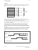
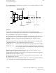
12.23.4 Example of function
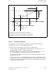
For reasons of simplicity, this example refers only to two axes of the 1st channel. In the
example, the X axis is the abscissa and the Y axis the ordinate (see MD 1100, 5480, 5500 and
5520).
Default settings:
SD 5001.0 = 1 ; "Actual-value display for workpiece" function active
NC MD5153.1 = 0 ; After NC start, reset position ZO from MD 1120 = G54 and TO
= D0 active.
NC MD1100 = 17 ; Plane G17 (X abscissa and Y ordinate) has been selected in the
1st channel to define the reference for tool offsets during
machining.
NC MD5480 = 0000 ; (address name X abscissa)
NC MD5500 = 0001 ; (address name Y ordinate)
NC MD5520 = 0010 ; (address name Z co-ordinate), the plane names of the co-ordinate
system are assigned to the axes listed above in the 1st channel.
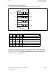
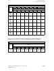
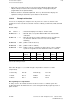
Zero offset G54
(coarse)
G54 (fine) G55
(coarse)
G55 (fine) G56
(coarse)
G56 (fine)
X axis -54.0 0 -0.55 -55.0 0 0
Y axis -54.0 0 -0.55 -55.0 0 0
Table: ZO data referring to example
Active TO = D3 (type = 1, a tool with 2 length compensations and tool nose radius
compensation)
L1 Geometry P2=-90 L2 Geometry P3=-180
L1 Wear P5=-9 L2 Wear P6=-18
L1 Basis P8=-1 L2 Basis P8=-2
Note regarding tool compensation:
L1 always refers to the ordinate and L2 to the abscissa of the co-ordinate system. The
assignment between the TO and the axes can be changed in the NC program by means of
plane selection.
12–242
© Siemens AG 1992 All Rights Reserved 6FC5197- AA50
SINUMERIK 840C (IA)