
Computer Drive Installation Instructions


12 Functional Descriptions 12.93
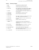
12.24.5 Travel to fixed stop with programmable clamping torque
12.24.5.2 SIMODRIVE 611A MSD or SIMODRIVE 660
With these systems, the drive is switched over from torque-limited operation to torque-
controlled operation after the fixed stop is reached. In this way, a torque of any desired value
(0.1 to 99.9% of max. torque) can be specified via the setpoint interface.
Setpoints must be input via terminals 56/14.
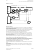
Hardware connections:
611 MSD, 660
NC
PLC
Measu-
ring
circuit
Outputs
Input
Sensor signal for
"Fixed stop reached"
(optional)
E1 Torque-controlled
operation
E1 C-axis operation
117
118
119
24
8
56
14
Speed
setpoint 1
Speed
setpoint 2
Gear stage
changeover
Po 39
1st torque
limitation
.
.
.
1
2
8
Functional sequence
The control must switch the spindle to C-axis operation before the function is selected. It does
this by activating terminal E1 (C-axis operation) of the drive actuator.
The NC detects selection of function G221 (via G function or command channel) during block
processing and informs the PLC that the function has been selected via the interface signal
TRAVEL TO FIXED STOP ACTIVE.
The PLC then activates the free gear stage, in which the torque limitation is operative, via
terminals 117, 118 and 119 and outputs the interface signal ACKNOWLEDGEMENT TRAVEL
TO FIXED STOP ACTIVE to the NC.
The rotary axis then starts to traverse at the programmed velocity.
As soon as the C axis has reached the fixed stop, the following error increases. As a result of
the increase in the following error above the threshold set in NC MD 1280* or owing to the
input signal of a sensor (which is passed on to the PLC-NC interface), the control detects that
the fixed stop has been reached.
12–250
© Siemens AG 1992 All Rights Reserved 6FC5197- AA50
SINUMERIK 840C (IA)