
Computer Drive Installation Instructions


12.93 12 Functional Descriptions
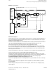
12.24.7 Diagrams for selection/deselection of travel to fixed stop
12.24.7.4 Meaning of signals
1. G220 Deselection block for travel to fixed stop
1. G221 Selection block for travel to fixed stop
2. NFAFAKT Interface signal "Travel to fixed stop" active
3. PLCOUT 96 PLC output which is connected to term. 96 (611 FD) or
gear stage changeover (611 MSD, 660). The MSD have
1-3 terminals available for gear stage changeover.
4. QFAFAKT PLC acknowledgement for the interface signal "Travel to
fixed stop active"
5. FANSCHLAG Servo signal to VIL: "Fixed stop reached".
6. NFESTANER Interface signal "Fixed stop reached
7. Speed setpoint
8. PLCOUT 22 PLC output for switchover to current-controlled operation.
This output is connected to term. 22 (611).
9. QFESTANER PLC acknowledgement for interface signal "Fixed stop
reached"
10. Distance-to-go Initiation of deletion of distance-to-go
11. Speed-controlled
operation Separate position control loop and switch the axis
internally to follow-up mode (principle of operation as for
spindle mode).
12. Block change A block change is initiated on termination of "Travel to
fixed stop" function.
13. Current setpoint Current setpoint transfer between VIL and servo
14. Current setpoint DAC Current setpoint output via measuring circuit
15. VRED_FFA The "Travel to fixed stop active" signal informs the servo
that "Travel to fixed stop" is active
16. S_FANSCHLAG Sensor signal "Fixed stop reached" from VIL: to servo
© Siemens AG 1992 All Rights Reserved 6FC5197- AA50
12–255
SINUMERIK 840C (IA)