
Computer Drive Installation Instructions


12 Functional Descriptions 10.94
12.27.3 Switchover
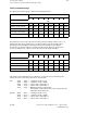
In addition to variable increment evaluation, a gear ratio can be activated additionally via
parameters "Number of teeth, motor" and "Number of teeth, spindle". This is necessary when
gear ratios change as a result of gear changes (with indirect actual value sensing).
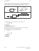
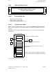
Gear ratios, numbers of teeth, paths
n1
n2
n1
zm
zs
n2
xg
xs
xt
R
R
MG
The gear ratio specifies the speed ratio between the drive and output ends:
n1 zs
R = ––– = –––
n2 zm
n1 = Drive speed
n2 = Output speed
zs = Output (spindle) number of teeth
zm = Drive (spindle) number of teeth
The ratio between the numbers of teeth (can be directly entered in new machine data) is
always inversely proportional to the ratio between the speeds.
The path on the workpiece side is thus calculated as follows:
xt = xs * h
or
zm
xt = xg * h * –––
zs
xt =Workpiece path
xs =Spindle path
xg =Motor path
h =Spindle pitch
12–278
© Siemens AG 1992 All Rights Reserved 6FC5197- AA50
SINUMERIK 840C (IA)