
Computer Drive Installation Instructions


10.94 12 Functional Descriptions
12.27.4 Diagnosis
12.27.4 Diagnosis
The currently effective parameter sets in the various parameter groups are displayed in the NC
service display for axes/spindles in the individual displays.
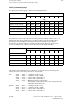
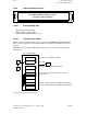
Structure of service displays:
Service Axes Individual display Axis: 1
Following error
Absolute actual value
Absolute setpoint
Abs. compensation value
Speed setpoint
Part actual value
Part setpoint
Contour deviation
Synchronism error
Parameter set position control
Parameter set ratio
Service number
(0.01 %)
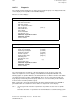
Service Spindle Individual display Spindle: 1
Speed setpoint
Progr. speed setpoint
Current speed setpoint
Actual speed value
Position setpoint
Actual position value
Following error
Synchronism error
Override
Current gear stage
Parameter set position control
Parameter set ratio
Service number
(0.01 %)
(rev/min)
(rev/min)
(rev/min)
(degrees)
(degrees)
(%)
The current parameter set numbers of the two parameter groups "Position control" and
"Ratio" are output in the services displays "Axis individual" and "Spindle individual". The
following applies to spindles: When the extended parameter set swithover function and "Switch
over parameter groups together" setting (MD 522*, bit 4 = 0) are selected, the "Actual gear
stage" display is irrelevant; parameter group switchover is executed entirely via the interface
for the "Position controller" parameter group.
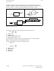
When a gear ratio is incorrectly parameterized, the alarm "Parameterization error NC-MD" is
generated and the associated new service number is output in the service display:
312 = Incorrect gear ratio entered for a parameter set (number of teeth, motor or spindle
= 0).
Gear ratio other than 1:1 specified for an axis with distance-coded measuring system.
© Siemens AG 1992 All Rights Reserved 6FC5197- AA50
12–279
SINUMERIK 840C (IA)