
Computer Drive Installation Instructions


04.96 12 Functional Descriptions
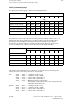
12.28.4 Format of interface data blocks
DL 0 bit 8 "Strobe":
Strobe for activation of configuring channel. Set by PLC user and reset by NCK
after acceptance (or rejection with error code) of configuration.
DL 0 bit 14 "Read/write":
Definition of transmission direction: 0 = PLC reads, 1 = PLC writes.
DL0 bit 15 "With acknowledgement":
If this bit is set, the writer (NCK or PLC) may not enter a new value until the last
value to be entered has been fetched by the reader (PLC or NCK). When a high-
speed data channel is operated "with acknowledgement", no semaphores are
required to ensure consistent data transmission; control bit "new value" in the
data transfer area (see DB 3) performs the requisite synchronization.
DR 0 Error code of NC:
Error code Description
80H Function identifier incorrect
40H Configuring parameter 1 incorrect
41H Configuring parameter 2 incorrect
42H Configuring parameter 3 incorrect
43H Configuring parameter 4 incorrect
20H No. of data transfer area incorrect/pointer to data transfer area incorrect
10H Write not permissible
11H Impermissible operating mode in DL 0
01H Too many data channels configured
02H Option not activated
03H Wrong update rate
If a fault occurs, the configuration is rejected. The corresponding data transfer area is no
longer processed by the NC, until there is a reconfiguration.
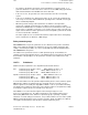
DL 1 "Job number":
Since the configuration for a number of data transfer areas is defined via one
channel only and consecutively for the areas concerned, there is no longer any
assignment between the currently supplied data and their meaning in the
interface DB 3. The user must manage this correlation himself outside the
interface DB 3. To facilitate diagnosis, the PLC user can assign a job number
when he configures a data transfer area; if the configuration is successful, this
number is signalled back by the NC in the appropriate data transfer area in DB 3.
DR 1 "No. of data transfer area":
The data transfer areas are numbered consecutively, starting with 1, in the
interface DB3.
DL 2 "Updating rate":
The rate at which this channel is processed by the NC, i.e. after how many IPO
cycles, can be set here. 1 means that the channel is processed in every IPO
cycle.
DR 2 "Function identifier" (for a description see Section "Overview of function
identifiers and configuring data (DB 2, DR 2 ... DR 6)"
DL 3 DRG configuring parameters 1 .. 4 (for a description see Section "Overview of
function identifiers and configuring data (DB 2, DR 2 ... DR 6)"
© Siemens AG 1992 All Rights Reserved 6FC5197- AA50
12–285
SINUMERIK 840C (IA)