
Computer Drive Installation Instructions

01.99 12 Functional Descriptions
12.29.1 Functional description
Measuring block parameter:
MT = Measuring sensor input
Depending on the hardware, inputs 1 or 2 can be measuring sensor inputs. Sensor input one 1
is effective on all measuring circuit hardware (detailed description in section 12.29.2, Hardware
- secondary conditions for measuring).
Example:
MT=1 Activation of measuring sensor input 1
MT=2 Activation of measuring sensor input 2
MT=R<No.> Activation of the measuring sensor input which is stored in the R parameter
under its number
MF=Measuring system edge
The measuring system edge specifies on which edge of the measuring sensor signal the
measured value of the axes should be recorded.
Example:
MF=1 Measured value recording at positive edge
MF=-1 Measured value recording at negative edge (effective with all measuring
circuit hardware
MF=2 Measured value recording of each edge change beginning with the first
positive edge
MF=-2 Measured value recording of each edge change beginning with the first
negative edge
MF=R<No.> Measured value recording depending on the contents of the R parameter
Measuring axes
Measured values can be recorded simultaneously for a maximum of 5 axes. Axis programming
can be carried out directly or indirectly.
Example:
X1=Y1=Z1=C1=C2= Measuring axes are the specified axes
@441 <No.> Measuring axis is the axis specified by a global axis
MS=Start parameter
The start parameter is the R parameter as from which measuring data are stored for the
respective axis. At least one start parameter has to be specified. With multiple
measuring axes and one start parameter the control automatically recalculates the
other start parameters according to the number of measured values. Individual start
parameters can also be specified for each measuring axis. The 1st programmed start
parameter must therefore be assigned to the 1st measuring axis, the 2nd programmed start
parameter to the 2nd measuring axis etc.
The number of actual measurements is entered in the R parameter specified by the start
parameter. The measured values are then listed in ascending order in the following R
parameters.
Example:
MS=1099 Start parameter is the R parameter R1099
MS=R<No.> Start parameter is the R parameter the number of which is recorded in the
specified R parameter
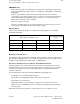
Structure of the R parameter field
R<Start parameter> Number of actual measurements
R<Start parameter+1> 1st measured value
R<Start parameter+2> 2nd measured value
..
..
R<Start parameter+No. of measured values> last measured value
© Siemens AG 1992 All Rights Reserved 6FC5197- AA50
12–299
SINUMERIK 840C (IA)