
Computer Drive Installation Instructions


12 Functional Descriptions 08.96
12.33.3 Current setpoint filter
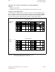
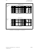
Possible filter combinations
Filter 4 Filter 3 Filter 2 Filter 1 MD 1201
PT2 PT2 PT2 PT2 = 0 0000
PT2 PT2 PT2 BS = 1 0001
PT2 PT2 BS PT2 0010
PT2 PT2 BS BS 0011
PT2 BS PT2 PT2 0100
PT2 BS PT2 BS 0101
PT2 BS BS PT2 0110
PT2 BS BS BS 0111
BS PT2 PT2 PT2 1000
BS PT2 PT2 BS 1001
BS PT2 BS PT2 1010
BS PT2 BS BS 1011
BS BS PT2 PT2 1101
BS BS PT2 BS 1101
BS BS BS PT2 1110
BS BS BS BS 1111
Note
Filter 1 is configured as a low-pass filter as standard.
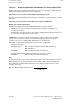
12.33.3.2 Scope of application of low pass as current setpoint filter
Low-pass filters must be dimensioned such that resonance is kept reliably low while the filter
effect on the fundamental frequency range is minimized.
Filter in the case of resonance in the fundamental frequency range
Resonance in the fundamental frequency range can normally be restricted by means of control
parameters.
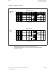
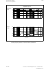
Note
Smoothing filters have a negative phase rotation (low-pass generally, bandstop for f < fs, fs
= blocking frequency). This phase rotation can reduce the stability margin of the fundamental
frequency range.
When a filter is used, therefore, the objective must be to obtain the optimum from
• desired damping action and
• minimum possible filter effects on the fundamental frequency range.
12–340
© Siemens AG 1992 All Rights Reserved 6FC5197- AA50
SINUMERIK 840C (IA)