
Computer Drive Installation Instructions

12 Functional Descriptions 08.96
12.33.3 Current setpoint filter
Example of bandstop filter application
The example below explains the basic procedure for applying one or several current setpoint
filters.
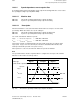
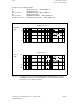
Peaks have been measured at 900 Hz and 1200 Hz.
Bandstop filters must be used to dampen both resonant frequencies. The speed controller can
then be set more finely to improve the inadequate dynamic response of the drive.
• Default settings
Filter 1 (activated as standard)
Low pass with fe 2000 Hz and
d 0.7
Reduction of amplitude response well above the fundamental frequency range,
minimization of effects of torque control loop on speed control loop.
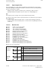
• Filters 2 and 3 must be parameterized as the bandstop.
MD 1200: Number of current setpoint filters = 3
MD 1201: Type of current setpoint filter = 6
• Enter frequency.
Filter 2:
MD 1213: Blocking frequency current setpoint filter 2 = 900 Hz
Filter 3:
MD 1216: Blocking frequency current setpoint filter 3 = 1200 Hz
• Enter bandwidth.
Half the measured resonant frequency is recommended as a guide value for the bandwidth
to be entered.
Filter 2:
MD 1213/2 = 900 Hz/ 2 = 450 Hz
MD 1214: Bandwidth current setpoint filter 1 = 450 Hz
Filter 2:
MD 1216/2 = 1200 Hz/ 2 = 600 Hz
MD 1217: Bandwidth current setpoint filter 2 = 600 Hz
• Enter counter bandwidth
Filter 2:
MD 1215: Counter bandwidth current setpoint filter 1 = 0.0 (default)
Filter 3:
MD 1218: Counter bandwidth current setpoint filter 2 = 0.0 (default)
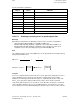
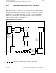
After the filters have been activated, the speed control loop is measured again. The
measurement result indicates whether and to what extent the resonance has been dampened
as a result of the filters. If the signals are now below the 0 dB line, the speed controller
parameters can be adjusted again.
If the measurement results are unsatisfactory, an attempt can be made to improve the effect of
the filters by varying the filter bandwidth (filter 2 MD 1214, filter 3 MD 1217).
Criteria for filter setting:
• Minimum additive phase rotation as a result of "Bandwidth" parameter. Filter effects on
fundamental frequency range are thus minimized.
• Maximum damping effect as a result of pole point compensation (reduce amplitude peak to
between 0 and approximately +3 dB).
12–346
© Siemens AG 1992 All Rights Reserved 6FC5197- AA50
SINUMERIK 840C (IA)